shaft ISUZU TROOPER 1998 Service Owner's Manual
[x] Cancel search | Manufacturer: ISUZU, Model Year: 1998, Model line: TROOPER, Model: ISUZU TROOPER 1998Pages: 3573, PDF Size: 60.36 MB
Page 158 of 3573

1B Ð 32 AIR CONDITIONING
3. Drive Belt
1) Temporary tighten the power steering pump unit
fixing bolts.
2) Push the drive belt when the force of 98N {10kgf}.,
and adjust the drive belt tension by tightening
drive belt tension adjustment bolt, till the 14 ~17
mm (0.55 ~0.67 in) of deflection of the belt is
obtained. Then tighten the power steering pump
fixing bolts.
2. Magnetic Clutch Harness Connector
1. Air Duct (Turbo to air cleaner)
CompressorTension adjustment bolt
Tension pally
14~17mm
(0.55-0.67in)
98N{10kgf}
Crank shaft pully
850RY00003
Page 259 of 3573
COMPRESSOR OVERHAUL 1D Ð 3
solvent, and dried with dry air. Use only lint free
cloths to wipe parts.
The operations described below are based on
bench overhaul with compressor removed from the
car, except as noted. They have been prepared in
order of accessibility of the components. When the
compressor is removed from the car for servicing,
the oil remaining in the compressor should be
discarded and new refrigerant oil added to the
compressor.
Magnetic clutch assembly repair procedures require
that the system be discharged of refrigerant. (Refer
to Section 1B for ÒREFRIGERANT RECOVERYÓ.)
Compressor malfunction will appear in one of four
ways: noise, seizure, leakage or low discharge
pressure. Resonant compressor noises are not
cause for alarm; however, irregular noise or rattles
may indicate broken parts or excessive clearances
due to wear. To check seizure, de-energize the
magnetic clutch and check to see if the drive plate
can be rotated. If rotation is impossible, the
compressor is seized. Low discharge pressure may
be due to a faulty internal seal of the compressor,
or a restriction in the compressor. Low discharge
pressure may also be due to an insufficient
refrigerant charge or a restriction elsewhere in the
system. These possibilities should be checked prior
to servicing the compressor. If the compressor is
inoperative, but is not seized, check to see if current
is being supplied to the magnetic clutch coil
terminals.
The compressor has vanes built into a rotor which
is mounted on a shaft.
When the shaft rotates, the vanes built into the
cylinder block assembly are opened by centrifugal
force.
This changes the volume of the space formed by
the rotor and cylinder, resulting in the intake and
compression of the refrigerant gas. The discharge
valve and the valve stopper, which protects the
discharge valve, are built into the cylinder block
assembly. There is no suction valve but a shaft seal
is installed between the shaft and head; a trigger
valve, which applies back pressure to the vanes, is
installed in the cylinder block and a refrigerant gas
temperature sensor is installed in the front head.
The specified quantity of compressor oil is
contained in the compressor to lubricate the various
parts using the refrigerant gas discharge pressure.
6VD1 engine is equipped with an invariable
capacity five-vane rotary compressor (DKV-14D
Type).
The compressor sucks and compresses refrigerant
by the rotation of the vane installed to the shaft,
and always discharges a fixed amount of refrigerant
independent of the load of refrigerant.The thermo sensor is installed to the front head of
the compressor to protect it by stopping its
operation when the refrigerant gas is insufficient or
when the temperature get abnormally high.
·OFF ..... 160 ±5¡C (320.0 ±9.0¡F)
·ON ..... 135 ±5¡C (275.0 ±9.0¡F)
4JG2 Engine are provided with a swash plate type
compressor (DKS-15CH Type)
Swash plate compressors have a swash (slanted)
plate mounted on the shaft. When the shaft turns,
the rotation of the swash plate is converted to
reciprocating piston motion which sucks in and
compresses the refrigerant gas.
Shaft seal (Lip type) is installed between the valve
plate and shaft & cylinder head to prevent
refrigerant gas leaks. A specified amount of
compressor oil is contained in the oil pan.
This oil is supplied to the cylinders, bearings, etc.,
by an oil pump which is connected to the swash
plate shaft.
With some compressors the differential between
the intake pressure and discharge pressure
generated while the compressor is operating is
used for lubrication instead of an oil pump.
Three pistons are arranged at 120g intervals around
the center of the swash plate shaft. These pistons
are connected to the ends of the swash plate
through shoe disks and balls.
The rotation of the swash plate causes
reciprocating movement of the piston inside the
cylinders, with each piston operating as two
cylinders. Because of that, the compressor operates
as though it has 6 cylinders.
The specified amount of the compressors oil is
150cc (4.2 Imp fl oz).
Also, compressor oil to be used varies according to
the compressor model. Be sure to avoid mixing two
or more different types of oil.
If the wrong oil is used, lubrication will be poor and
the compressor will seize or malfunction.
Page 264 of 3573
1D Ð 8 COMPRESSOR OVERHAUL
Inspection and Repair
Drive Plate
If the frictional surface shows signs of damage due to
excessive heat, the drive plate and pulley should be
replaced.
Pulley Assembly
Check the appearance of the pulley assembly. If the
frictional surface of the pulley shows signs of excessive
grooving due to slippage, both the pulley and drive
plate should be replaced. The frictional surfaces of the
pulley assembly should be cleaned with a suitable
solvent before reinstallation.
Coil
Check coil for loose connector or cracked insulation.
Installation
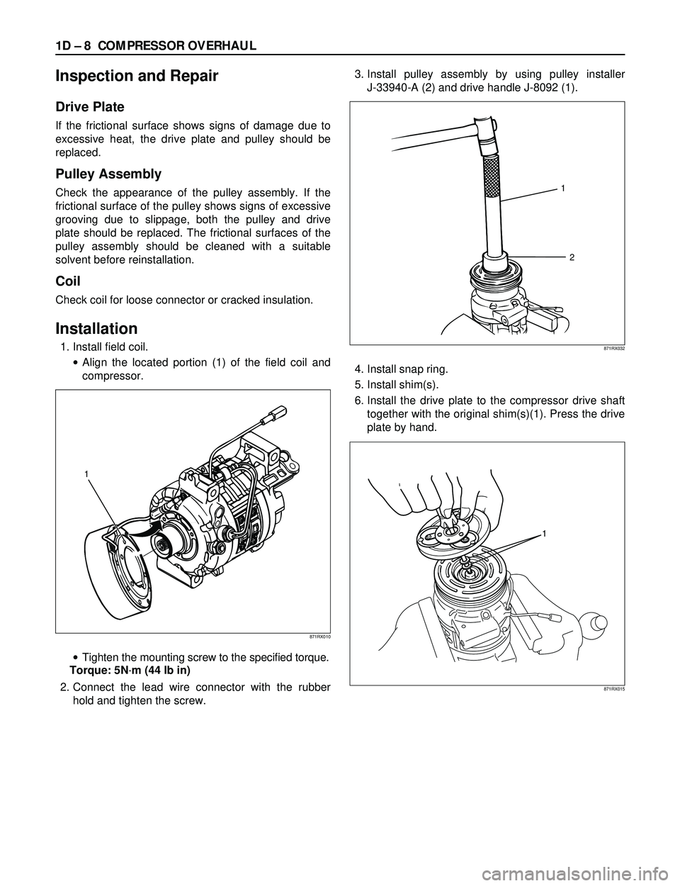
1. Install field coil.
·Align the located portion (1) of the field coil and
compressor.
·Tighten the mounting screw to the specified torque.
Torque: 5Nám (44 lb in)
2. Connect the lead wire connector with the rubber
hold and tighten the screw.3. Install pulley assembly by using pulley installer
J-33940-A (2) and drive handle J-8092 (1).
4. Install snap ring.
5. Install shim(s).
6. Install the drive plate to the compressor drive shaft
together with the original shim(s)(1). Press the drive
plate by hand.
1
2
871RX032
1
871RX010
1
871RX015
Page 266 of 3573
1D Ð 10 COMPRESSOR OVERHAUL
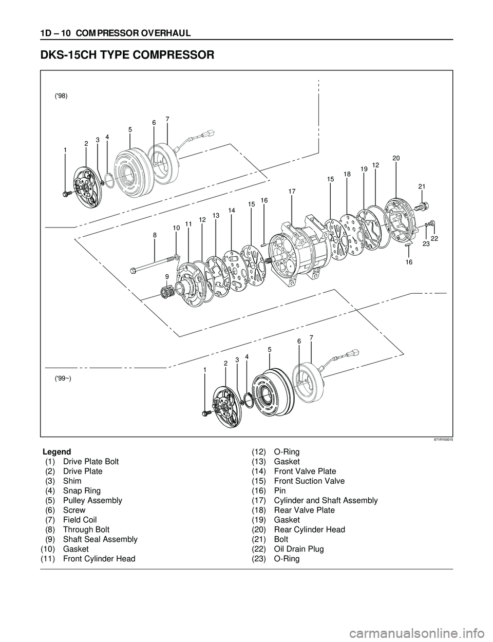
Legend
(1) Drive Plate Bolt
(2) Drive Plate
(3) Shim
(4) Snap Ring
(5) Pulley Assembly
(6) Screw
(7) Field Coil
(8) Through Bolt
(9) Shaft Seal Assembly
(10) Gasket
(11) Front Cylinder Head(12) O-Ring
(13) Gasket
(14) Front Valve Plate
(15) Front Suction Valve
(16) Pin
(17) Cylinder and Shaft Assembly
(18) Rear Valve Plate
(19) Gasket
(20) Rear Cylinder Head
(21) Bolt
(22) Oil Drain Plug
(23) O-Ring
DKS-15CH TYPE COMPRESSOR
16
23 2122 6
7
45
321 ('98)
('99~)
67
45
321
8
910111213141516
17
1518191220
871RY00015
Page 268 of 3573
1D Ð 12 COMPRESSOR OVERHAUL
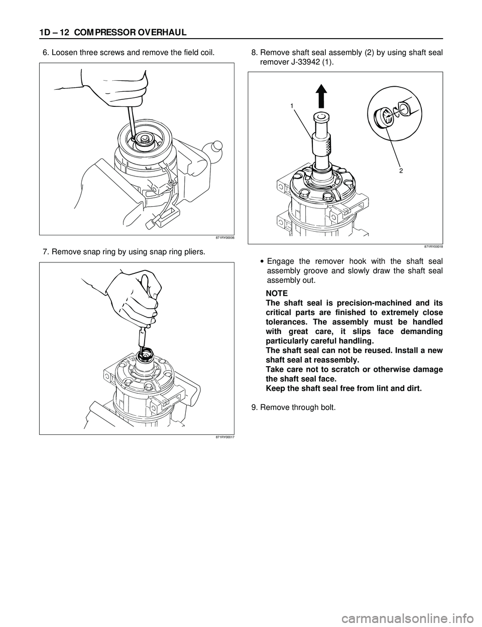
6. Loosen three screws and remove the field coil.
7. Remove snap ring by using snap ring pliers.8. Remove shaft seal assembly (2) by using shaft seal
remover J-33942 (1).
·Engage the remover hook with the shaft seal
assembly groove and slowly draw the shaft seal
assembly out.
NOTE
The shaft seal is precision-machined and its
critical parts are finished to extremely close
tolerances. The assembly must be handled
with great care, it slips face demanding
particularly careful handling.
The shaft seal can not be reused. Install a new
shaft seal at reassembly.
Take care not to scratch or otherwise damage
the shaft seal face.
Keep the shaft seal free from lint and dirt.
9. Remove through bolt.
871RY00006
871RY00017
1
2
871RY00018
Page 269 of 3573
COMPRESSOR OVERHAUL 1D Ð 13
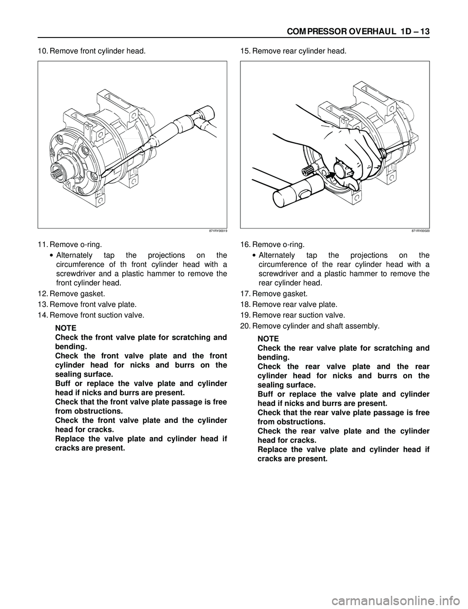
10. Remove front cylinder head.
11. Remove o-ring.
·Alternately tap the projections on the
circumference of th front cylinder head with a
screwdriver and a plastic hammer to remove the
front cylinder head.
12. Remove gasket.
13. Remove front valve plate.
14. Remove front suction valve.
NOTE
Check the front valve plate for scratching and
bending.
Check the front valve plate and the front
cylinder head for nicks and burrs on the
sealing surface.
Buff or replace the valve plate and cylinder
head if nicks and burrs are present.
Check that the front valve plate passage is free
from obstructions.
Check the front valve plate and the cylinder
head for cracks.
Replace the valve plate and cylinder head if
cracks are present.15. Remove rear cylinder head.
16. Remove o-ring.
·Alternately tap the projections on the
circumference of the rear cylinder head with a
screwdriver and a plastic hammer to remove the
rear cylinder head.
17. Remove gasket.
18. Remove rear valve plate.
19. Remove rear suction valve.
20. Remove cylinder and shaft assembly.
NOTE
Check the rear valve plate for scratching and
bending.
Check the rear valve plate and the rear
cylinder head for nicks and burrs on the
sealing surface.
Buff or replace the valve plate and cylinder
head if nicks and burrs are present.
Check that the rear valve plate passage is free
from obstructions.
Check the rear valve plate and the cylinder
head for cracks.
Replace the valve plate and cylinder head if
cracks are present.
871RY00019871RY00020
Page 270 of 3573
1D Ð 14 COMPRESSOR OVERHAUL
Installation
1. Install cylinder and shaft assembly.
·Clamp the cylinder shaft assembly in a vise.
The rear side of the cylinder shaft assembly must
be facing up.
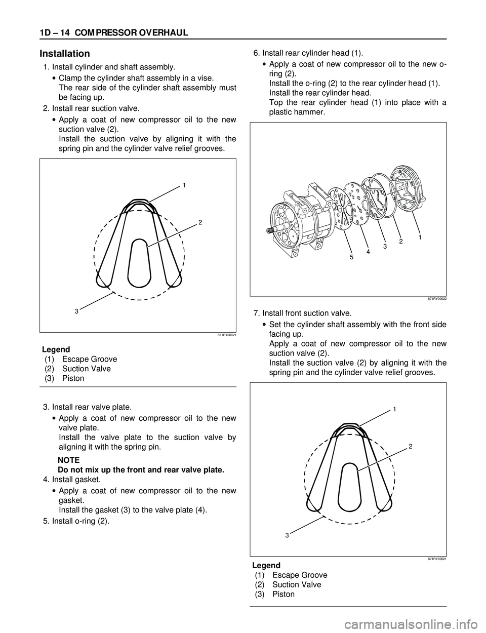
2. Install rear suction valve.
·Apply a coat of new compressor oil to the new
suction valve (2).
Install the suction valve by aligning it with the
spring pin and the cylinder valve relief grooves.
Legend
(1) Escape Groove
(2) Suction Valve
(3) Piston
3. Install rear valve plate.
·Apply a coat of new compressor oil to the new
valve plate.
Install the valve plate to the suction valve by
aligning it with the spring pin.
NOTE
Do not mix up the front and rear valve plate.
4. Install gasket.
·Apply a coat of new compressor oil to the new
gasket.
Install the gasket (3) to the valve plate (4).
5. Install o-ring (2).6. Install rear cylinder head (1).
·Apply a coat of new compressor oil to the new o-
ring (2).
Install the o-ring (2) to the rear cylinder head (1).
Install the rear cylinder head.
Top the rear cylinder head (1) into place with a
plastic hammer.
7. Install front suction valve.
·Set the cylinder shaft assembly with the front side
facing up.
Apply a coat of new compressor oil to the new
suction valve (2).
Install the suction valve (2) by aligning it with the
spring pin and the cylinder valve relief grooves.
Legend
(1) Escape Groove
(2) Suction Valve
(3) Piston
1
2
3
871RY00021
54321
871RY00022
1
2
3
871RY00021
Page 271 of 3573

COMPRESSOR OVERHAUL 1D Ð 15
8. Install front valve plate.
·Apply a coat of new compressor oil to the new
valve plate.
Install the valve plate to the suction valve by
aligning it with the spring pin.
NOTE
Do not mix up the front and rear valve plates.
9. Install gasket
·Apply new compressor oil to the new gasket.
·Install the gasket to the valve plate by a aligning it
with the spring pin.
10. Install o-ring.
11. Install front cylinder head.
·Apply a coat of new compressor oil to the new O-
ring.
Install the O-ring to the front cylinder head.
Install the front cylinder head.
Tap the front cylinder head into place with a
plastic hammer.
NOTE
When installing the cylinder head, be careful
that the end of the drive shaft does not
damage the shaft seal assembly surface in the
cylinder head.12. Install through bolt.
·Gaskets cannot reused. Always replace new
ones. Tighten the bolts to the specified torque a
little at a time in the sequence shown in the
illustration.
Torque: 22Nám (16 lbáft)
NOTE
Rotate the compressor drive shaft two or three
times to make sure that it moves smoothly.
1
4
5
2
3
6
871RY00016
871RY00023
Page 272 of 3573
1D Ð 16 COMPRESSOR OVERHAUL
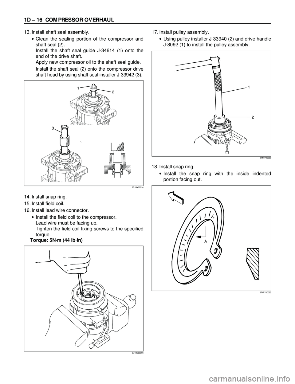
13. Install shaft seal assembly.
·Clean the sealing portion of the compressor and
shaft seal (2).
Install the shaft seal guide J-34614 (1) onto the
end of the drive shaft.
Apply new compressor oil to the shaft seal guide.
Install the shaft seal (2) onto the compressor drive
shaft head by using shaft seal installer J-33942 (3).
14. Install snap ring.
15. Install field coil.
16. Install lead wire connector.
·Install the field coil to the compressor.
Lead wire must be facing up.
Tighten the field coil fixing screws to the specified
torque.
Torque: 5Nám (44 lbáin)17. Install pulley assembly.
·Using pulley installer J-33940 (2) and drive handle
J-8092 (1) to install the pulley assembly.
18. Install snap ring.
·Install the snap ring with the inside indented
portion facing out.
871RY00006
32 1
871RY00024
A
871RY00025
1
2
871RY00008
Page 273 of 3573
COMPRESSOR OVERHAUL 1D Ð 17
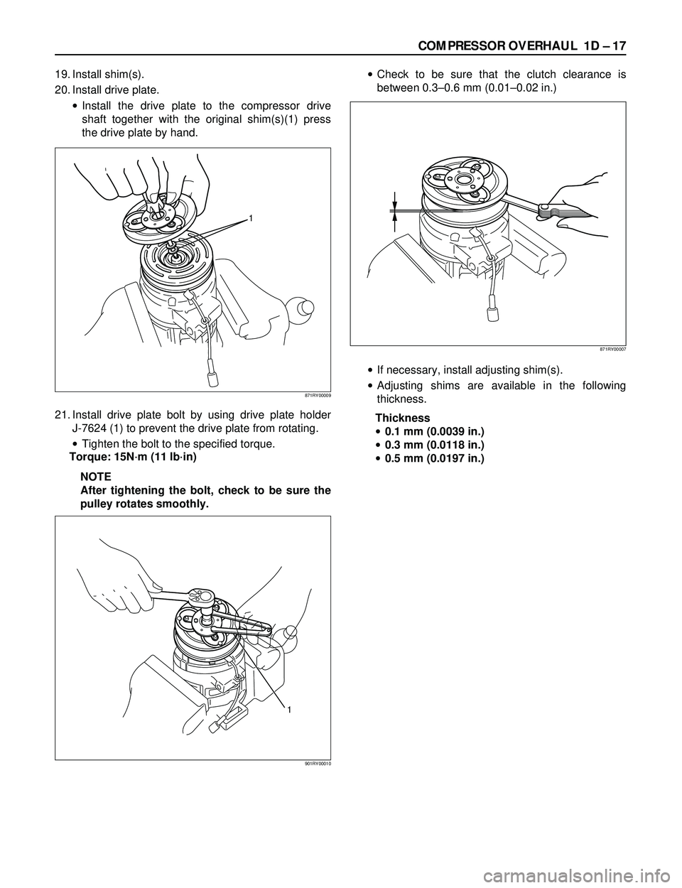
19. Install shim(s).
20. Install drive plate.
·Install the drive plate to the compressor drive
shaft together with the original shim(s)(1) press
the drive plate by hand.
21. Install drive plate bolt by using drive plate holder
J-7624 (1) to prevent the drive plate from rotating.
·Tighten the bolt to the specified torque.
Torque: 15Nám (11 lbáin)
NOTE
After tightening the bolt, check to be sure the
pulley rotates smoothly.·Check to be sure that the clutch clearance is
between 0.3Ð0.6 mm (0.01Ð0.02 in.)
·If necessary, install adjusting shim(s).
·Adjusting shims are available in the following
thickness.
Thickness
·0.1 mm (0.0039 in.)
·0.3 mm (0.0118 in.)
·0.5 mm (0.0197 in.)
1
871RY00009
871RY00007
1
901RY00010