shaft ISUZU TROOPER 1998 Service Workshop Manual
[x] Cancel search | Manufacturer: ISUZU, Model Year: 1998, Model line: TROOPER, Model: ISUZU TROOPER 1998Pages: 3573, PDF Size: 60.36 MB
Page 332 of 3573
2A – 30 POWER STEERING
Vane
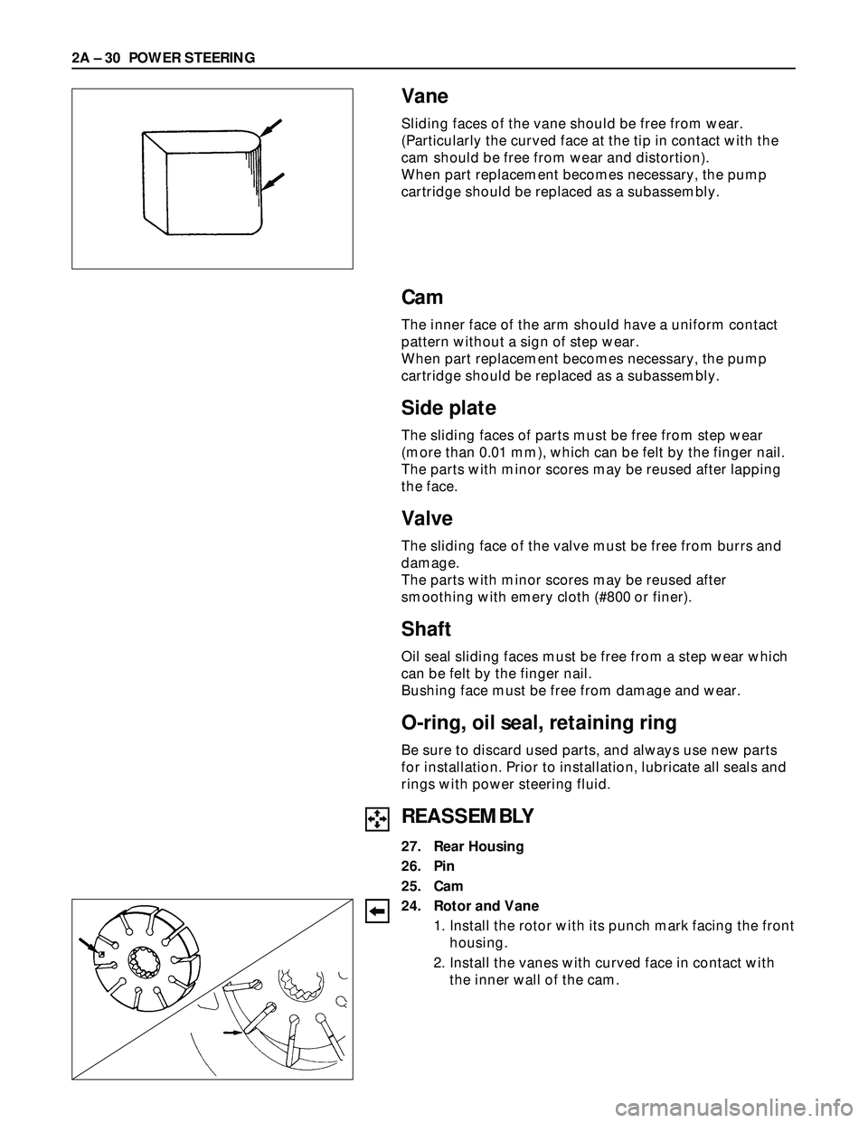
Sliding faces of the vane should be free from wear.
(Particularly the curved face at the tip in contact with the
cam should be free from wear and distortion).
When part replacement becomes necessary, the pump
cartridge should be replaced as a subassembly.
Cam
The inner face of the arm should have a uniform contact
pattern without a sign of step wear.
When part replacement becomes necessary, the pump
cartridge should be replaced as a subassembly.
Side plate
The sliding faces of parts must be free from step wear
(more than 0.01 mm), which can be felt by the finger nail.
The parts with minor scores may be reused after lapping
the face.
Valve
The sliding face of the valve must be free from burrs and
damage.
The parts with minor scores may be reused after
smoothing with emery cloth (#800 or finer).
Shaft
Oil seal sliding faces must be free from a step wear which
can be felt by the finger nail.
Bushing face must be free from damage and wear.
O-ring, oil seal, retaining ring
Be sure to discard used parts, and always use new parts
for installation. Prior to installation, lubricate all seals and
rings with power steering fluid.
REASSEMBLY
27. Rear Housing
26. Pin
25. Cam
24. Rotor and Vane
1. Install the rotor with its punch mark facing the front
housing.
2. Install the vanes with curved face in contact with
the inner wall of the cam.
Page 333 of 3573
POWER STEERING 2A – 31
23. Pressure Plate
CAUTION:
When installing side plate, be careful not to damage its
inner surface. Damaged side plate may cause poor pump
performance, pump seizure or oil leakage.
22. Front Housing
21. O-ring
20. O-ring
Be sure to discard used O-rings, and always use new
parts for installation.
19. Gasket
Be sure to discard used parts, and always use new
parts for installation.
18. Rear Housing Assembly and Pump Cartridge
17. Bolt
Rear Housing Bolt Torque N·m (kg·m/lb·ft)
17.6 (1.8 / 12.8)
16. Oil Seal
Be sure to discard used parts, and always use new
parts for installation.
CAUTION:
When installing the oil seal, be careful not to damage the
oil seal contacting surface of the housing.
15. Retaining Ring
14. Shaft
13. Bearing
12. Shaft Assembly
11. Retaining Ring
10. Pressure switch
Pressure Switch Torque N·m (kg·m/lb·ft)
20 (2.0 / 14)
9. Spring
8. Filter
7. Retaining Ring
6. Valve
5. O-ring
Be sure to discard used parts, and always use new
parts for installation.
4. Connector
Connector Torque N·m (kg·m/lb·ft)
74 (7.5 / 54)
3. O-ring
Be sure to discard used parts, and always use new
parts for installation.
2. Pipe, Suction
1. Bolt
Suction Pipe Bolt Torque N·m (kg·m/lb·ft)
15.7 (1.6 / 11.5)
Page 334 of 3573
2A – 32 POWER STEERING
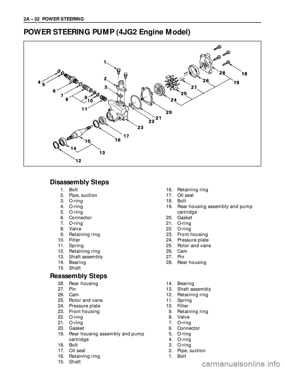
POWER STEERING PUMP (4JG2 Engine Model)
Disassembly Steps
1. Bolt
2. Pipe, suction
3. O-ring
4. O-ring
5. O-ring
6. Connector
7. O-ring
8. Valve
9. Retaining ring
10. Filter
11. Spring
12. Retaining ring
13. Shaft assembly
14. Bearing
15. Shaft16. Retaining ring
17. Oil seal
18. Bolt
19. Rear housing assembly and pump
cartridge
20. Gasket
21. O-ring
22. O-ring
23. Front housing
24. Pressure plate
25. Rotor and vane
26. Cam
27. Pin
28. Rear housing
Reassembly Steps
28. Rear housing
27. Pin
26. Cam
25. Rotor and vane
24. Pressure plate
23. Front housing
22. O-ring
21. O-ring
20. Gasket
19. Rear housing assembly and pump
cartridge
18. Bolt
17. Oil seal
16. Retaining ring
15. Shaft14. Bearing
13. Shaft assembly
12. Retaining ring
11. Spring
10. Filter
9. Retaining ring
8. Valve
7. O-ring
6. Connector
5. O-ring
4. O-ring
3. O-ring
2. Pipe, suction
1. Bolt
Page 335 of 3573
POWER STEERING 2A – 33
DISASSEMBLY
Preparation:
Clean oil pump with solvent (its plug discharge and
suction port to prevent the entry of solvent). Be careful not
to expose the oil seal of shaft assembly to solvent.
1. Bolt
2. Pipe, Suction
3. O-ring
4. O-ring
5. O-ring
6. Connector
7. O-ring
8. Valve
9. Retaining Ring
10. Filter
11. Spring
12. Retaining Ring
13. Shaft Assembly
14. Bearing
15. Shaft
16. Retaining Ring
17. Oil Seal
CAUTION:
When removing the oil seal, be careful not to damage the
housing.
18. Bolt
19. Rear Housing Assembly and Pump Cartridge
20. Gasket
21. O-ring
22. O-ring
23. Front Housing
24. Pressure Plate
25. Rotor and Vane
26. Cam
27. Pin
28. Rear Housing
Page 337 of 3573
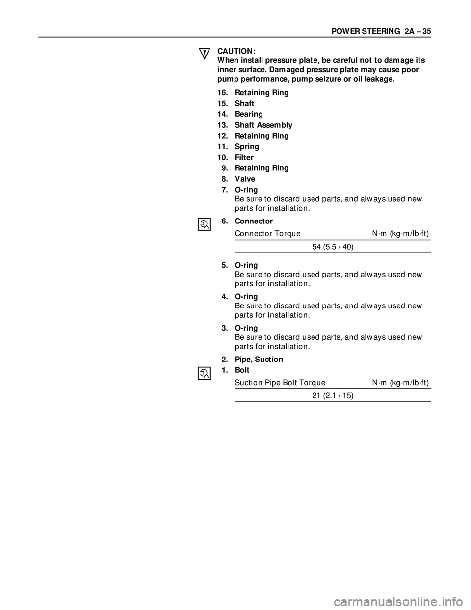
POWER STEERING 2A – 35
CAUTION:
When install pressure plate, be careful not to damage its
inner surface. Damaged pressure plate may cause poor
pump performance, pump seizure or oil leakage.
16. Retaining Ring
15. Shaft
14. Bearing
13. Shaft Assembly
12. Retaining Ring
11. Spring
10. Filter
9. Retaining Ring
8. Valve
7. O-ring
Be sure to discard used parts, and always used new
parts for installation.
6. Connector
Connector Torque N·m (kg·m/lb·ft)
54 (5.5 / 40)
5. O-ring
Be sure to discard used parts, and always used new
parts for installation.
4. O-ring
Be sure to discard used parts, and always used new
parts for installation.
3. O-ring
Be sure to discard used parts, and always used new
parts for installation.
2. Pipe, Suction
1. Bolt
Suction Pipe Bolt Torque N·m (kg·m/lb·ft)
21 (2.1 / 15)
Page 338 of 3573
2A – 36 POWER STEERING
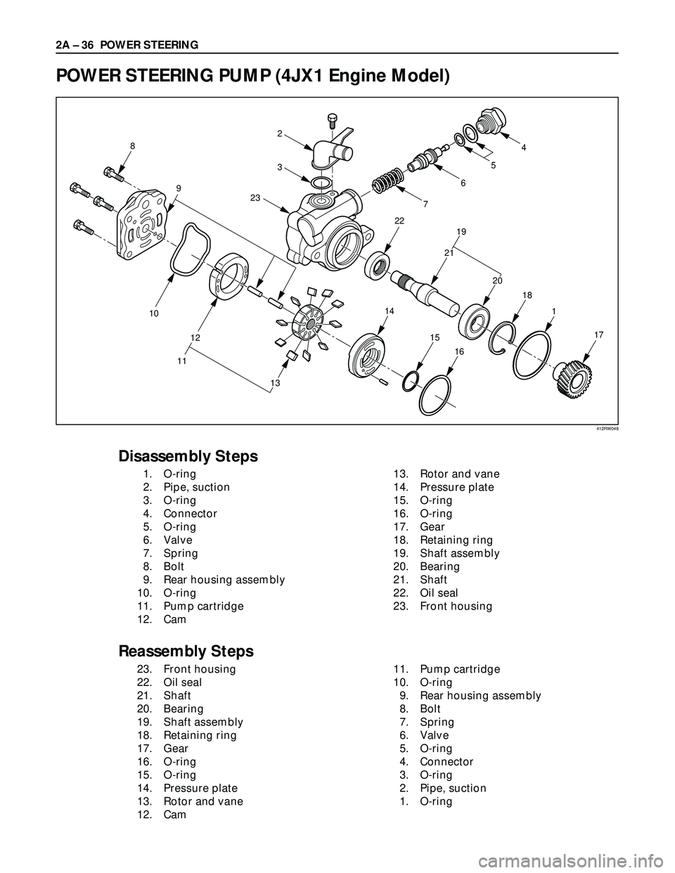
POWER STEERING PUMP (4JX1 Engine Model)
17 1 18 227654
3 2
19
20 2115
14
16
8
10
12
11
13 9
23
Disassembly Steps
1. O-ring
2. Pipe, suction
3. O-ring
4. Connector
5. O-ring
6. Valve
7. Spring
8. Bolt
9. Rear housing assembly
10. O-ring
11. Pump cartridge
12. Cam13. Rotor and vane
14. Pressure plate
15. O-ring
16. O-ring
17. Gear
18. Retaining ring
19. Shaft assembly
20. Bearing
21. Shaft
22. Oil seal
23. Front housing
Reassembly Steps
23. Front housing
22. Oil seal
21. Shaft
20. Bearing
19. Shaft assembly
18. Retaining ring
17. Gear
16. O-ring
15. O-ring
14. Pressure plate
13. Rotor and vane
12. Cam11. Pump cartridge
10. O-ring
9. Rear housing assembly
8. Bolt
7. Spring
6. Valve
5. O-ring
4. Connector
3. O-ring
2. Pipe, suction
1. O-ring
412RW048
Page 339 of 3573
POWER STEERING 2A – 37
DISASSEMBLY
Preparation:
Clean oil pump with solvent (plug the discharge and
suction port to prevent the entry of solvent). Be careful not
to expose the oil seal of shaft assembly to solvent.
1. O-ring
2. Pipe, Suction
3. O-ring
4. Connector
5. O-ring
6. Valve
7. Spring
8. Bolt
9. Rear Housing Assembly
10. O-ring
11. Pump Cartridge
12. Cam
13. Rotor and Vane
14. Pressure Plate
15. O-ring
16. O-ring
17. Gear
18. Retaining Ring
19. Shaft Assembly
20. Bearing
21. Shaft
22. Oil seal
CAUTION:
When removing the oil seal, be careful not to damage the
housing.
23. Front Housing
Page 340 of 3573
2A – 38 POWER STEERING
REASSEMBLY
23. Front Housing
22. Oil Seal
Be sure to discard used parts, and always used new
parts for installation.
21. Shaft
20. Bearing
19. Shaft Assembly
18. Retaining Ring
17. Gear
16. O-ring
Be sure to discard used parts, and always used new
parts for installation.
15. O-ring
Be sure to discard used parts, and always used new
parts for installation.
14. Pressure Plate
CAUTION:
When install pressure plate, be careful not to damage its
inner surface. Damaged pressure plate may cause poor
pump performance, pump seizure or oil leakage.
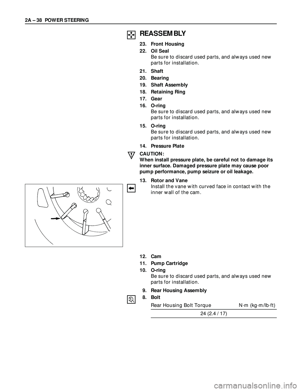
13. Rotor and Vane
Install the vane with curved face in contact with the
inner wall of the cam.
12. Cam
11. Pump Cartridge
10. O-ring
Be sure to discard used parts, and always used new
parts for installation.
9. Rear Housing Assembly
8. Bolt
Rear Housing Bolt Torque N·m (kg·m/lb·ft)
24 (2.4 / 17)
Page 354 of 3573
This steering wheel and column repair section
covers the Supplemental Restraint System (SRS)
steering column. The following repair procedures
are specific to SRS Components. When servicing a
vehicle equipped with Supplemental Restraint
System, pay close attention to all WARNINGS and
CAUTIONS.
For detailed explanation about SRS, refer to Section
9J "SUPPLEMENTAL RESTRAINT SYSTEM (SRS)"
of manual.
The steering column has three important features in
addition to the steering function:
1. The column is energy absorbing, designed to
compress in a front-end collision to minimize
the possibility of injury to the driver of the
vehicle.
2. The ignition switch and lock are mounted
conveniently on the column.
3. With the column mounted lock, the ignition
and steering operation can be locked to
prevent theft of the vehicle.
The column may be disassembled and
reassembled. To insure the energy absorbing
action, it is important that the specified screws,
bolts and nuts be used only as designated and that
they are tightened to the specified torque.
When the column is removed from the vehicle, a
sharp blow on the end of steering shaft or shift
lever, leaning on the column assembly, or dropping
the assembly could shear or loosen the fasteners
that maintain column rigidity.
WARNING
THIS VEHICLE HAS A SUPPLEMENTAL RE-
STRAINT SYSTEM (SRS).REFER TO THE SRS
COMPONENT AND WIRING LOCATION VIEW
IN ORDER TO DETERMINE WHETHER YOU ARE
PERFORMING SERVICE ON OR NEAR THE SRS
COMPONENTS OR THE SRS WIRING. WHEN
YOU ARE PERFORMING SERVICE ON OR NEAR
THE SRS COMPONENTS OR THE SRS WIRING,
REFER TO THE SRS SERVICE INFORM ATION.
FAILURE TO FOLLOW WARNINGS COULD RE-
SULT IN POSSIBLE AIR BAG DEPLOYMENT,
PERSONAL INJURY, OR OTHERWISE UN-
NEEDED SRS SYSTEM REPAIRS.
SAFE HANDLING OF INFLATOR MODULES
REQUIRES FOLLOWING THE PROCEDURES
DESCRIBED BELOW FOR BOTH LIVE AND
DEPLOYED MODULES.
SAFETY PRECAUTIONS MUST BE FOLLOWEDWHEN HANDLING A DEPLOYED AIR BAG AS-
SEMBLY (AIR BAG). AFTER DEPLOYMENT,
THE AIR BAG ASSEMBLY (AIR BAG) SURFACE
MAY CONTAIN A SMALL AMOUNT OF SODIUM
HYDROXIDE, A BY-PRODUCT OF THE DEPLOY-
MENT REACTION, THAT IS IRRITATING TO THE
SKIN AND EYES.MOST OF THE POWDER ON
THE AIR BAG ASSEMBLY (AIR BAG) IS HARM-
LESS. AS A PRECAUTION, WEAR GLOVES
AND SAFETY GLASSES WHEN HANDLING A
DEPLOYED AIR BAG ASSEMBLY, AND WASH
YOUR HANDS WITH MILD SOAP AND WATER
AFTERWARDS.
WHEN CARRYING A LIVE AIR BAG ASSEMBLY,
MAKE SURE THE BAG AND TRIM COVER ARE
POINTED AWAY FROM YOU. NEVER CARRY
AN AIR BAG ASSEMBLY BY THE WIRES OR
CONNECTOR ON THE UNDERSIDE OF MODULE.
IN THE CASE OF AN ACCIDENTAL DEPLOY-
MENT, THE BAG WILL THEN DEPLOY WITH
MINIMAL CHANCE OF INJURY. WHEN PLACING
A LIVE AIR BAG ASSEMBLY ON A BENCH OR
OTHER SURFACE, ALWAYS FACE THE BAG AND
TRIM COVER UP, AWAY FROM THE SURFACE.
NEVER REST A STEERING COLUMN ASSEMBLY
ON THE STEERING WHEEL WITH THE AIR
BAG ASSEMBLY FACE DOWN AND COLUMN
VERTICAL.THIS IS NECESSARY SO THAT A
FREE SPACE IS PROVIDED TO ALLOW THE AIR
BAG ASSEMBLY TO EXPAND IN THE UNLIKELY
EVENT OF ACCIDENTAL DEPLOYMENT. OTHER-
WISE, PERSONAL INJURY COULD RESULT.
TO AVOID DEPLOYMENT WHEN TROUBLE
SHOOTING THE SRS SYSTEM, DO NOT USE
ELECTRICAL TEST EQUIPMENT, SUCH AS
BATTERY-POWERED OR A/C-POWERED VOLT-
METER, OHMMETER, ETC., OR ANY TYPE OF
ELECTRICAL EQUIPMENT OTHER THAN SPECI-
FIED IN THIS MANUAL. DO NOT USE A NON-
POWERED PROBE-TYPE TESTER.
INSTRUCTIONS IN THIS MANUAL MUST BE
FOLLOWED CAREFULLY, OTHERWISE PER-
SONAL INJURY MAY RESULT. 2A – 52 SUPPLEMENTAL RESTRAINT SYSTEM STEERING WHEEL & COLUMN
GENERAL DESCRIPTION
Page 359 of 3573
SUPPLEMENTAL RESTRAINT SYSTEM STEERING WHEEL & COLUMN 2A – 57
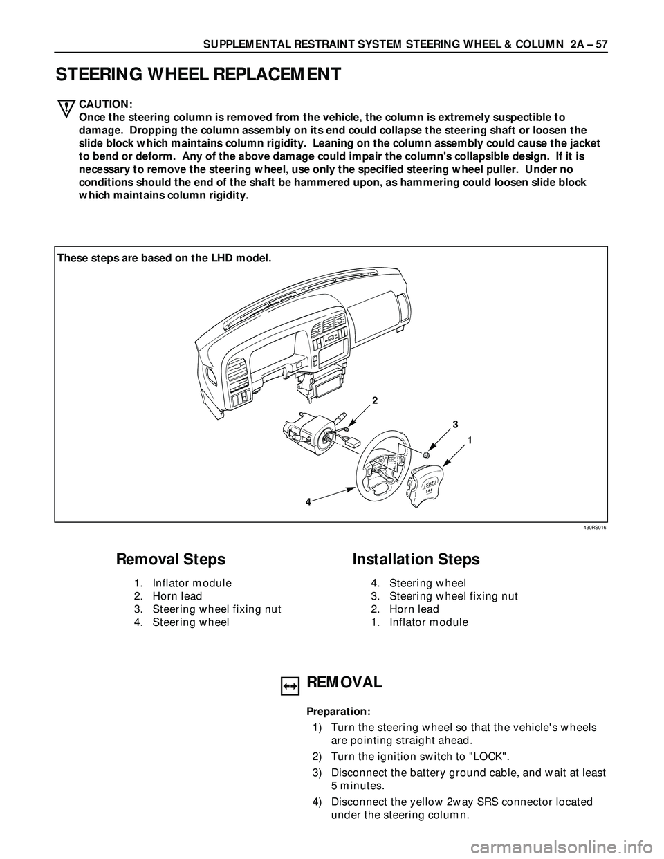
STEERING WHEEL REPLACEMENT
1
3
2
4
Removal Steps
1. Inflator module
2. Horn lead
3. Steering wheel fixing nut
4. Steering wheel
Installation Steps
4. Steering wheel
3. Steering wheel fixing nut
2. Horn lead
1. Inflator module
430RS016
These steps are based on the LHD model.
REMOVAL
Preparation:
1) Turn the steering wheel so that the vehicle's wheels
are pointing straight ahead.
2) Turn the ignition switch to "LOCK".
3) Disconnect the battery ground cable, and wait at least
5 minutes.
4) Disconnect the yellow 2way SRS connector located
under the steering column. CAUTION:
Once the steering column is removed from the vehicle, the column is extremely suspectible to
damage. Dropping the column assembly on its end could collapse the steering shaft or loosen the
slide block which maintains column rigidity. Leaning on the column assembly could cause the jacket
to bend or deform. Any of the above damage could impair the column's collapsible design. If it is
necessary to remove the steering wheel, use only the specified steering wheel puller. Under no
conditions should the end of the shaft be hammered upon, as hammering could loosen slide block
which maintains column rigidity.