brake light ISUZU TROOPER 1998 Service Owner's Guide
[x] Cancel search | Manufacturer: ISUZU, Model Year: 1998, Model line: TROOPER, Model: ISUZU TROOPER 1998Pages: 3573, PDF Size: 60.36 MB
Page 881 of 3573
POWER ASSISTED BRAKE SYSTEM 5C – 3
BRAKE SYSTEM DIAGNOSIS
ROAD TESTING THE BRAKES
Brake Test
Brakes should be tested on a dry, clean, reasonably
smooth and level roadway. A true test of brake
performance cannot be made if the roadway is wet,
greasy or covered with loose dirt so that all tires do
not grip the road equally. Testing will also be
adversely affected if the roadway is crowned so as to
throw the weight of the vehicle toward wheels on one
side or if the roadway is so rough that wheels tend to
bounce. Test the brakes at different vehicle speeds
with both light and heavy pedal pressure; however,
avoid locking the wheels and sliding the tires. Locked
wheels and sliding tires do not indicate brake
efficiency, since heavily braked but turning wheels
will stop the vehicle in less distance than locked
wheels. More tire-to-road friction is present with a
heavily braked turning tire then with a sliding tire.
The standard brake system is designed and balanced
to avoid locking the wheels except at very high
deceleration levels.
It is designed this way because the shortest stopping
distance and best control is achieved without brake
lock-up.
Because of high deceleration capability, a firmer pedal
may be felt at higher deceleration levels.
External Conditions That Affect Brake
Performance
1. Tires: Tires having unequal contact and grip on the
road will cause unequal braking. Tires must be
equally inflated, identical in size, and the tread
pattern of right and left tires must be
approximately equal.
2. Vehicle loading: A heavily loaded vehicle requires
more braking effort.
3. Wheel Alignment: Misalignment of the wheels,
particularly in regard to excessive camber and
caster, will cause the brakes to pull to one side.
BRAKE FLUID LEAKS
With engine running at idle and the transmission in
“Neutral”, depress the brake pedal and hold a
constant foot pressure on the pedal. If pedal gradually
falls away with the constant pressure, the hydraulic
system may be leaking.
Check the master cylinder fluid level. While a slight
drop in reservoir level will result from normal lining
wear, an abnormally low level in resevoir indicates a
leak in the system. The hydraulic system may be
leaking internally as well as externally. Refer to
“Master Cylinder Inspection”. Also, the system may
appear to pass this test but still have slight leakage. If
fluid level is normal, check the vacuum booster push
Page 882 of 3573
5C – 4 POWER ASSISTED BRAKE SYSTEM
rod length. If an incorrect length push rod is found,
adjust or replace the push rod. Check the brake pedal
travel and the parking brake adjustment.
When checking the fluid level, the master cylinder
fluid level may be low from the “MAX” mark if the
front and rear linings are worn. This is not abnormal.
WARNING LIGHT OPERATION
When the ignition switch is in the START position, the
“BRAKE” warning light should glow and go OFF when
the ignition switch returns to the ON position.
The following conditions will activate the “BRAKE”
light:
1. Parking brake applied. The light should be ON
whenever the parking brake is applied and the
ignition switch is ON.
2. Low fluid level. A low fluid level in the master
cylinder will turn the “BRAKE” light ON.
3. During engine cranking the “BRAKE” light should
remain ON. This notifies the driver that the
warning circuit is operating properly.
4. Low vacuum warning light. The vacuum warning
device is equipped on the diesel engine equipped
vehicles. The “BRAKE” light comes on when the
reserved vacuum is lowered to a critical level or
power brake line is damaged.
NOTE:
Depressing the brake pedal repeatedly may cause the
brake warning light to come ON when the engine is
running at idling speed or at low speed. This is
because the amount of vacuum is used more than
that supplied by the vacuum pump, however, no
problem will occur actually.
If the lamp is still lighting even after 2 or 3 seconds at
idling speed, the vacuum line may be defective.
ANTILOCK BRAKE SYSTEM (ABS)
Refer to Brake Control System for inspection and
diagnosis procedure of the hydraulic unit.
Page 883 of 3573
POWER ASSISTED BRAKE SYSTEM 5C – 5
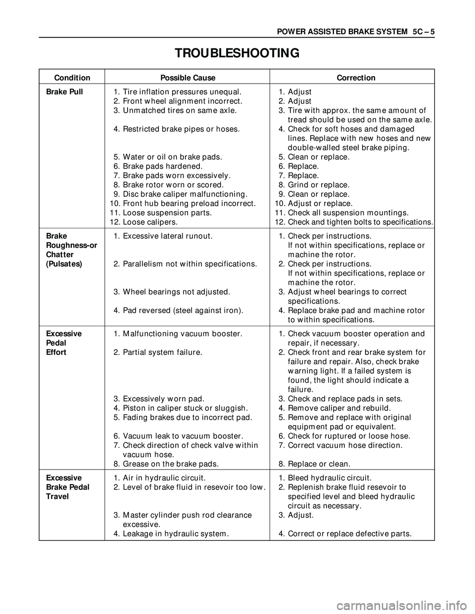
TROUBLESHOOTING
Condition Possible Cause Correction
Brake Pull1. Tire inflation pressures unequal. 1. Adjust
2. Front wheel alignment incorrect. 2. Adjust
3. Unmatched tires on same axle. 3. Tire with approx. the same amount of
tread should be used on the same axle.
4. Restricted brake pipes or hoses. 4. Check for soft hoses and damaged
lines. Replace with new hoses and new
double-walled steel brake piping.
5. Water or oil on brake pads. 5. Clean or replace.
6. Brake pads hardened. 6. Replace.
7. Brake pads worn excessively. 7. Replace.
8. Brake rotor worn or scored. 8. Grind or replace.
9. Disc brake caliper malfunctioning. 9. Clean or replace.
10. Front hub bearing preload incorrect. 10. Adjust or replace.
11. Loose suspension parts. 11. Check all suspension mountings.
12. Loose calipers. 12. Check and tighten bolts to specifications.
Brake 1. Excessive lateral runout. 1. Check per instructions.
Roughness-orIf not within specifications, replace or
Chattermachine the rotor.
(Pulsates)2. Parallelism not within specifications. 2. Check per instructions.
If not within specifications, replace or
machine the rotor.
3. Wheel bearings not adjusted. 3. Adjust wheel bearings to correct
specifications.
4. Pad reversed (steel against iron). 4. Replace brake pad and machine rotor
to within specifications.
Excessive 1. Malfunctioning vacuum booster. 1. Check vacuum booster operation and
Pedal repair, if necessary.
Effort2. Partial system failure. 2. Check front and rear brake system for
failure and repair. Also, check brake
warning light. If a failed system is
found, the light should indicate a
failure.
3. Excessively worn pad. 3. Check and replace pads in sets.
4. Piston in caliper stuck or sluggish. 4. Remove caliper and rebuild.
5. Fading brakes due to incorrect pad. 5. Remove and replace with original
equipment pad or equivalent.
6. Vacuum leak to vacuum booster. 6. Check for ruptured or loose hose.
7. Check direction of check valve within 7. Correct vacuum hose direction.
vacuum hose.
8. Grease on the brake pads. 8. Replace or clean.
Excessive 1. Air in hydraulic circuit. 1. Bleed hydraulic circuit.
Brake Pedal 2. Level of brake fluid in resevoir too low. 2. Replenish brake fluid resevoir to
Travelspecified level and bleed hydraulic
circuit as necessary.
3. Master cylinder push rod clearance 3. Adjust.
excessive.
4. Leakage in hydraulic system. 4. Correct or replace defective parts.
Page 884 of 3573
5C – 6 POWER ASSISTED BRAKE SYSTEM
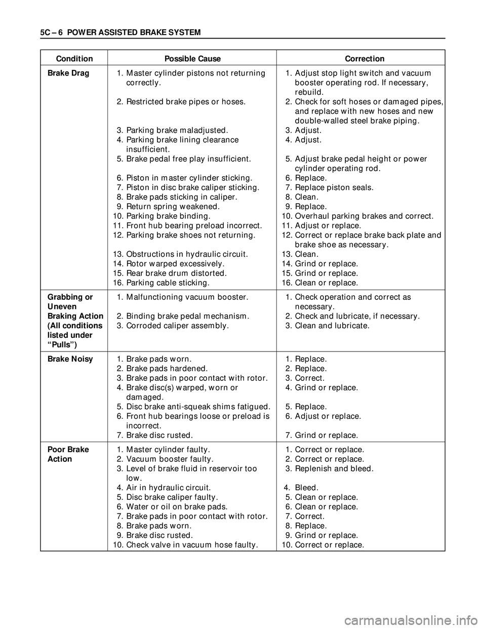
Condition Possible Cause Correction
Brake Drag1. Master cylinder pistons not returning 1. Adjust stop light switch and vacuum
correctly. booster operating rod. If necessary,
rebuild.
2. Restricted brake pipes or hoses. 2. Check for soft hoses or damaged pipes,
and replace with new hoses and new
double-walled steel brake piping.
3. Parking brake maladjusted. 3. Adjust.
4. Parking brake lining clearance 4. Adjust.
insufficient.
5. Brake pedal free play insufficient. 5. Adjust brake pedal height or power
cylinder operating rod.
6. Piston in master cylinder sticking. 6. Replace.
7. Piston in disc brake caliper sticking. 7. Replace piston seals.
8. Brake pads sticking in caliper. 8. Clean.
9. Return spring weakened. 9. Replace.
10. Parking brake binding. 10. Overhaul parking brakes and correct.
11. Front hub bearing preload incorrect. 11. Adjust or replace.
12. Parking brake shoes not returning. 12. Correct or replace brake back plate and
brake shoe as necessary.
13. Obstructions in hydraulic circuit. 13. Clean.
14. Rotor warped excessively. 14. Grind or replace.
15. Rear brake drum distorted. 15. Grind or replace.
16. Parking cable sticking. 16. Clean or replace.
Grabbing or1. Malfunctioning vacuum booster. 1. Check operation and correct as
Uneven necessary.
Braking Action 2. Binding brake pedal mechanism. 2. Check and lubricate, if necessary.
(All conditions3. Corroded caliper assembly. 3. Clean and lubricate.
listed under
“Pulls”)
Brake Noisy1. Brake pads worn. 1. Replace.
2. Brake pads hardened. 2. Replace.
3. Brake pads in poor contact with rotor. 3. Correct.
4. Brake disc(s) warped, worn or 4. Grind or replace.
damaged.
5. Disc brake anti-squeak shims fatigued. 5. Replace.
6. Front hub bearings loose or preload is 6. Adjust or replace.
incorrect.
7. Brake disc rusted. 7. Grind or replace.
Poor Brake1. Master cylinder faulty. 1. Correct or replace.
Action2. Vacuum booster faulty. 2. Correct or replace.
3. Level of brake fluid in reservoir too 3. Replenish and bleed.
low.
4. Air in hydraulic circuit. 4. Bleed.
5. Disc brake caliper faulty. 5. Clean or replace.
6. Water or oil on brake pads. 6. Clean or replace.
7. Brake pads in poor contact with rotor. 7. Correct.
8. Brake pads worn. 8. Replace.
9. Brake disc rusted. 9. Grind or replace.
10. Check valve in vacuum hose faulty. 10. Correct or replace.
Page 886 of 3573
5C – 8 POWER ASSISTED BRAKE SYSTEM
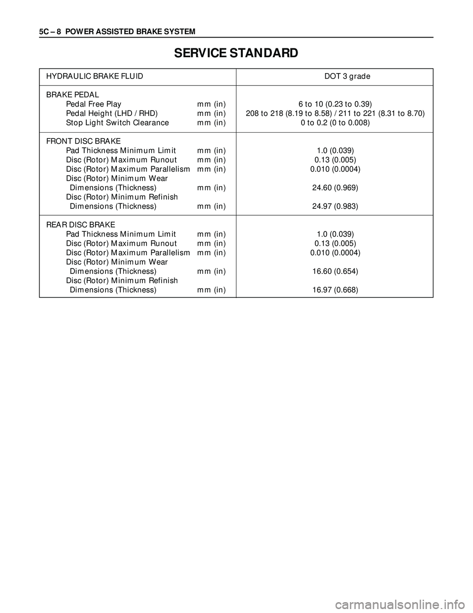
SERVICE STANDARD
HYDRAULIC BRAKE FLUID DOT 3 grade
BRAKE PEDAL
Pedal Free Play mm (in) 6 to 10 (0.23 to 0.39)
Pedal Height (LHD / RHD) mm (in) 208 to 218 (8.19 to 8.58) / 211 to 221 (8.31 to 8.70)
Stop Light Switch Clearance mm (in) 0 to 0.2 (0 to 0.008)
FRONT DISC BRAKE
Pad Thickness Minimum Limit mm (in) 1.0 (0.039)
Disc (Rotor) Maximum Runout mm (in) 0.13 (0.005)
Disc (Rotor) Maximum Parallelism mm (in) 0.010 (0.0004)
Disc (Rotor) Minimum Wear
Dimensions (Thickness) mm (in) 24.60 (0.969)
Disc (Rotor) Minimum Refinish
Dimensions (Thickness) mm (in) 24.97 (0.983)
REAR DISC BRAKE
Pad Thickness Minimum Limit mm (in) 1.0 (0.039)
Disc (Rotor) Maximum Runout mm (in) 0.13 (0.005)
Disc (Rotor) Maximum Parallelism mm (in) 0.010 (0.0004)
Disc (Rotor) Minimum Wear
Dimensions (Thickness) mm (in) 16.60 (0.654)
Disc (Rotor) Minimum Refinish
Dimensions (Thickness) mm (in) 16.97 (0.668)
Page 890 of 3573
5C – 12 POWER ASSISTED BRAKE SYSTEM
27. Depress the brake pedal to check if you feel
“sponginess” after the air has been removed from
all wheel cylinders and calipers. If the pedal feels
“spongy”, the entire bleeding procedure must be
repeated.
28. After the bleeding operation is completed on each
individual wheel, check the level of brake fluid in
the reservoir and replenish up to the “MAX” level if
necessary.
29. Attach the reservoir cap.
•If the diaphragm inside the cap is deformed,
reform it and install.
30. Stop the engine.
FLUSHING BRAKE HYDRAULIC SYSTEM
It is recommended that the entire hydraulic system be
thoroughly flushed with clean brake fluid whenever
new parts are installed in the hydraluic system.
Approximately one quart of fluid is required to flush
the hydraulic system.
The system must be flushed if there is any doubt as to
the grade of fluid in the system or if fluid has been
used which contains the slightest trace of mineral oil.
All rubber parts that have been subjected to a
contaminated fluid must be replaced.
BRAKE PIPES AND HOSES
The hydraulic brake system components are
interconnected by special steel piping and flexible
hoses. Flexible hoses are used between the frame and
the front calipers, the frame and rear axle case and the
rear axle and the rear calipers.
When the hydraulic pipes have been disconnected for
any reason, the brake system must be bled after
reconnecting the pipe; refer to “Bleeding Brake
Hydraulic System” in this section.
BRAKE HOSE INSPECTION
The brake hoses should be inspected at least twice a
year. The brake hose assembly should be checked for
road hazard, cracks and chafing of the outer cover,
and for leaks and blisters. Inspect for proper routing
and mounting of the hose. A brake hose that rubs on
suspension components will wear and eventually fail.
A light and mirror may be needed for an adequate
inspection. If any of the above conditions are
observed on the brake hose, adjust or replace the
hose as necessary.
CAUTION:
Never allow brake components such as calipers to
hang from the brake hoses, as damage to the hoses
may occur.
Page 891 of 3573
POWER ASSISTED BRAKE SYSTEM 5C – 13
CHECKING BRAKE PEDAL HEIGHT
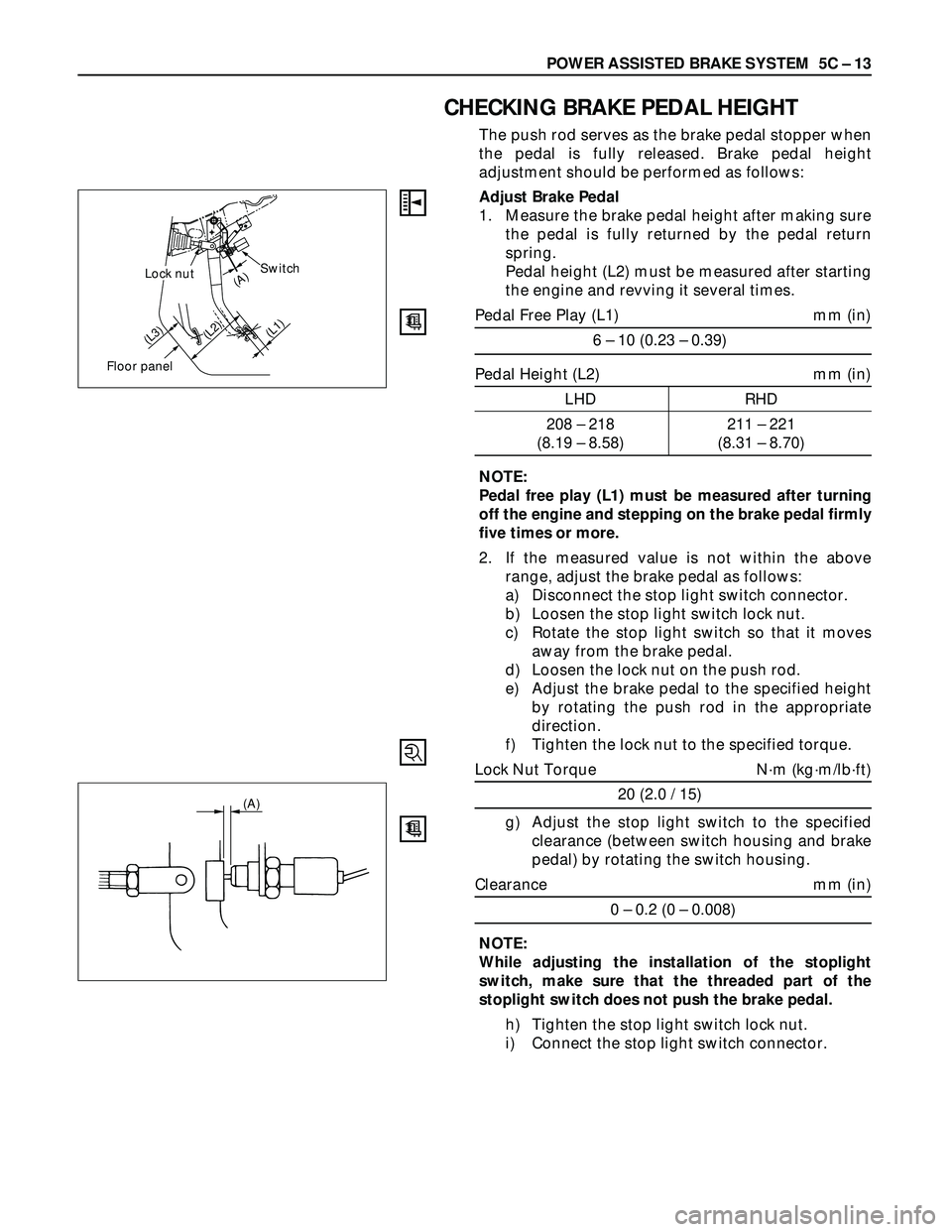
The push rod serves as the brake pedal stopper when
the pedal is fully released. Brake pedal height
adjustment should be performed as follows:
Adjust Brake Pedal
1. Measure the brake pedal height after making sure
the pedal is fully returned by the pedal return
spring.
Pedal height (L2) must be measured after starting
the engine and revving it several times.
Pedal Free Play (L1) mm (in)
6 – 10 (0.23 – 0.39)
Pedal Height (L2) mm (in)
LHD RHD
208 – 218 211 – 221
(8.19 – 8.58) (8.31 – 8.70)
NOTE:
Pedal free play (L1) must be measured after turning
off the engine and stepping on the brake pedal firmly
five times or more.
2. If the measured value is not within the above
range, adjust the brake pedal as follows:
a) Disconnect the stop light switch connector.
b) Loosen the stop light switch lock nut.
c) Rotate the stop light switch so that it moves
away from the brake pedal.
d) Loosen the lock nut on the push rod.
e) Adjust the brake pedal to the specified height
by rotating the push rod in the appropriate
direction.
f) Tighten the lock nut to the specified torque.
Lock Nut Torque N·m (kg·m/lb·ft)
20 (2.0 / 15)
g) Adjust the stop light switch to the specified
clearance (between switch housing and brake
pedal) by rotating the switch housing.
Clearance mm (in)
0 – 0.2 (0 – 0.008)
NOTE:
While adjusting the installation of the stoplight
switch, make sure that the threaded part of the
stoplight switch does not push the brake pedal.
h) Tighten the stop light switch lock nut.
i) Connect the stop light switch connector.
Switch
Floor panel
(L3)
(A)
(L2)(L1)
Lock nut
(A)
Page 906 of 3573
5C – 28 POWER ASSISTED BRAKE SYSTEM
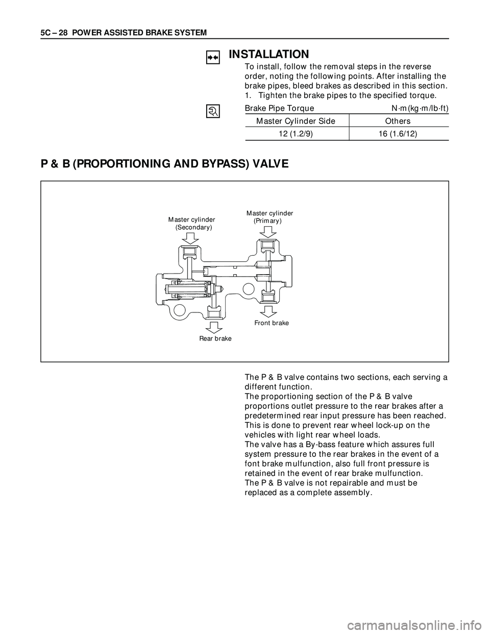
P & B (PROPORTIONING AND BYPASS) VALVE
Master cylinder
(Primary) Master cylinder
(Secondary)
Rear brakeFront brake
INSTALLATION
To install, follow the removal steps in the reverse
order, noting the following points. After installing the
brake pipes, bleed brakes as described in this section.
1. Tighten the brake pipes to the specified torque.
Brake Pipe Torque N·m(kg·m/lb·ft)
Master Cylinder Side Others
12 (1.2/9) 16 (1.6/12)
The P & B valve contains two sections, each serving a
different function.
The proportioning section of the P & B valve
proportions outlet pressure to the rear brakes after a
predetermined rear input pressure has been reached.
This is done to prevent rear wheel lock-up on the
vehicles with light rear wheel loads.
The valve has a By-bass feature which assures full
system pressure to the rear brakes in the event of a
font brake mulfunction, also full front pressure is
retained in the event of rear brake mulfunction.
The P & B valve is not repairable and must be
replaced as a complete assembly.
Page 912 of 3573
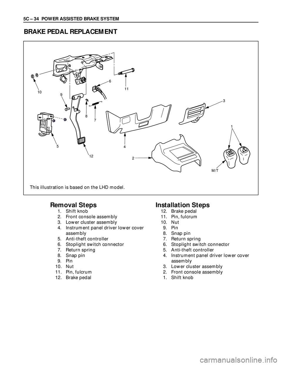
5C – 34 POWER ASSISTED BRAKE SYSTEM
BRAKE PEDAL REPLACEMENT
10
9
5
124
2 7 86
11
3
1
M/T
Removal Steps
1. Shift knob
2. Front console assembly
3. Lower cluster assembly
4. Instrument panel driver lower cover
assembly
5. Anti-theft controller
6. Stoplight switch connector
7. Return spring
8. Snap pin
9. Pin
10. Nut
11. Pin, fulcrum
12. Brake pedal
Installation Steps
12. Brake pedal
11. Pin, fulcrum
10. Nut
9. Pin
8. Snap pin
7. Return spring
6. Stoplight switch connector
5. Anti-theft controller
4. Instrument panel driver lower cover
assembly
3. Lower cluster assembly
2. Front console assembly
1. Shift knob
This illustration is based on the LHD model.
Page 913 of 3573
POWER ASSISTED BRAKE SYSTEM 5C – 35
REMOVAL
1. Shift Knob
2. Front Console Assembly
3. Lower Cluster Assembly
4. Instrument Panel Driver Lower Cover Assembly
5. Anti-theft Controller
6. Stoplight switch Connector
7. Return Spring
8. Snap Pin
9. Pin
10. Nut
11. Pin, Fulcrum
12. Brake Pedal
INSTALLATION
12. Brake Pedal
11. Pin, Fulcrum
•Apply grease to the entire circumference of the
fulcrum pin.
10. Nut
Bolt and Nut Torque N·m (kg·m / lb·ft)
33 (3.3 / 24)
9. Pin
•Apply grease to the entire circumference of the
push rod pin.
8. Snap Pin
•Adjust pedal free travel. Refer to “Brake Pedal
Adjustment” previously in this section.
7. Return Spring
6. Stoplight Switch Connector
5. Anti-theft Connector
4. Instrument Panel Driver Lower Cover Assembly
3. Lower Cluster Assembly
2. Front Console Assembly
1. Shift Knob