belt ISUZU TROOPER 1998 Service Manual Online
[x] Cancel search | Manufacturer: ISUZU, Model Year: 1998, Model line: TROOPER, Model: ISUZU TROOPER 1998Pages: 3573, PDF Size: 60.36 MB
Page 1532 of 3573
00 Ð 32 SERVICE INFORMATION
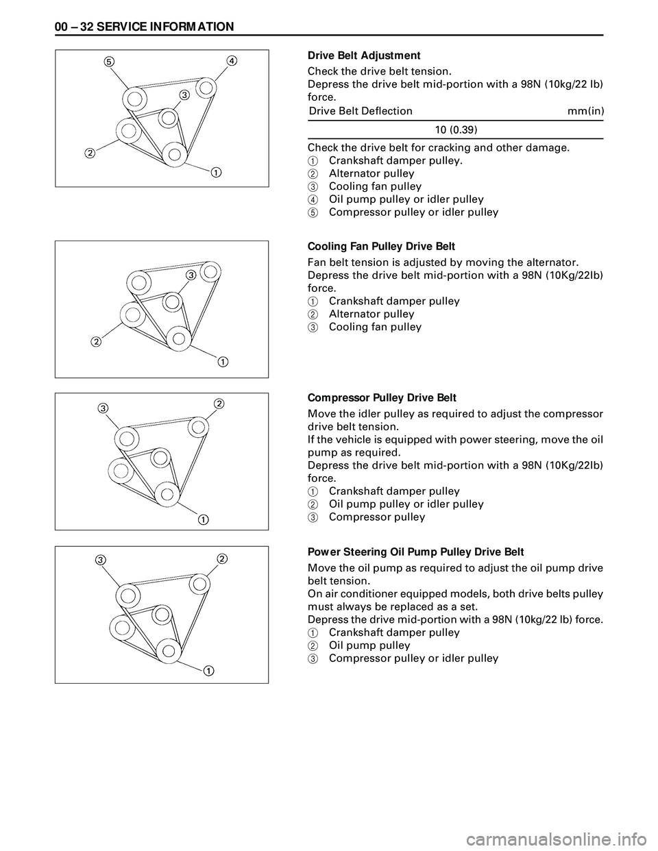
Drive Belt Adjustment
Check the drive belt tension.
Depress the drive belt mid-portion with a 98N (10kg/22 lb)
force.
Cooling Fan Pulley Drive Belt
Fan belt tension is adjusted by moving the alternator.
Depress the drive belt mid-portion with a 98N (10Kg/22lb)
force.
1Crankshaft damper pulley
2Alternator pulley
3Cooling fan pulley
Compressor Pulley Drive Belt
Move the idler pulley as required to adjust the compressor
drive belt tension.
If the vehicle is equipped with power steering, move the oil
pump as required.
Depress the drive belt mid-portion with a 98N (10Kg/22lb)
force.
1Crankshaft damper pulley
2Oil pump pulley or idler pulley
3Compressor pulley
Power Steering Oil Pump Pulley Drive Belt
Move the oil pump as required to adjust the oil pump drive
belt tension.
On air conditioner equipped models, both drive belts pulley
must always be replaced as a set.
Depress the drive mid-portion with a 98N (10kg/22 lb) force.
1Crankshaft damper pulley
2Oil pump pulley
3Compressor pulley or idler pulley Check the drive belt for cracking and other damage.
1Crankshaft damper pulley.
2Alternator pulley
3Cooling fan pulley
4Oil pump pulley or idler pulley
5Compressor pulley or idler pulley
10 (0.39)
mm(in) Drive Belt Deflection
Page 1613 of 3573
4JG2-NA/4JG2-TURBO ENGINE 6A2 Ð 11
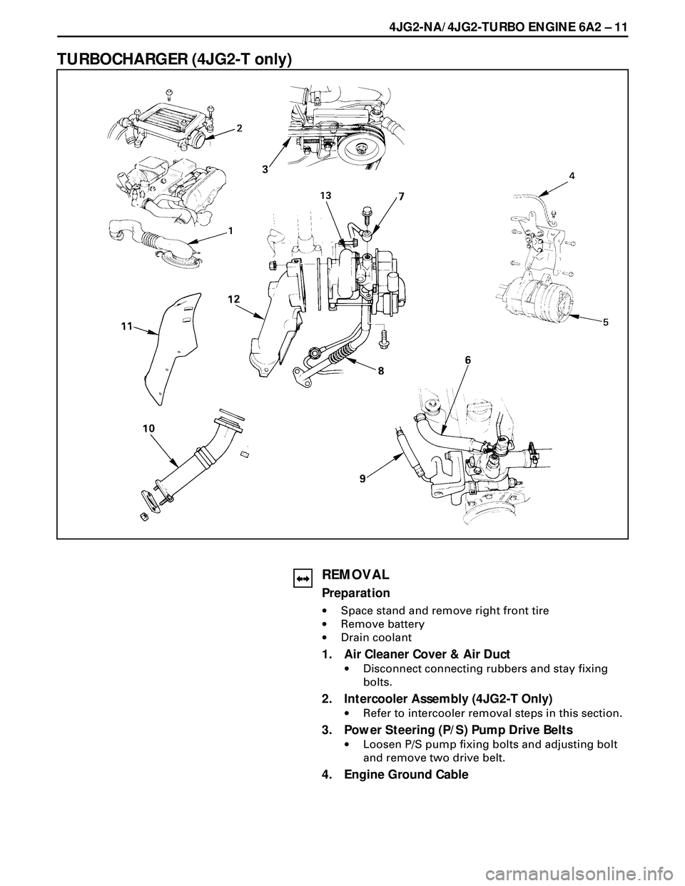
TURBOCHARGER (4JG2-T only)
REMOVAL
Preparation
·Space stand and remove right front tire
·Remove battery
·Drain coolant
1. Air Cleaner Cover & Air Duct
·Disconnect connecting rubbers and stay fixing
bolts.
2. Intercooler Assembly (4JG2-T Only)
·Refer to intercooler removal steps in this section.
3. Power Steering (P/S) Pump Drive Belts
·Loosen P/S pump fixing bolts and adjusting bolt
and remove two drive belt.
4. Engine Ground Cable
Page 1616 of 3573
6A2Ð 14 4JG2-NA/4JG2-TURBO ENGINE
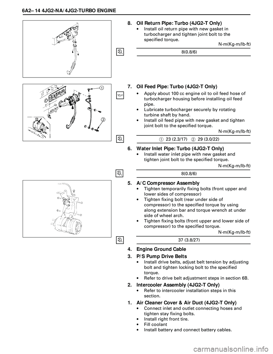
8. Oil Return Pipe: Turbo (4JG2-T Only)
·Install oil return pipe with new gasket in
turbocharger and tighten joint bolt to the
specified torque.
7. Oil Feed Pipe: Turbo (4JG2-T Only)
·Apply about 100 cc engine oil to oil feed hose of
turbocharger housing before installing oil feed
pipe.
·Lubricate turbocharger securely by rotating
turbine shaft by hand.
·Install oil feed pipe with new gasket and tighten
joint bolt to the specified torque.
6. Water Inlet Pipe: Turbo (4JG2-T Only)
·Install water inlet pipe with new gasket and
tighten joint bolt to the specified torque.
4. Engine Ground Cable
3. P/S Pump Drive Belts
·Install drive belts, adjust belt tension by adjusting
bolt and tighten locking bolt to the specified
torque.
·Refer to drive belt adjustment steps in section 6B.
2. Intercooler Assembly (4JG2-T Only)
·Refer to intercooler installation steps in this
section.
1. Air Cleaner Cover & Air Duct (4JG2-T Only)
·Connect inlet and outlet connecting hoses and
tighten stay fixing bolts.
·Install right front tire.
·Fill coolant
·Install battery and connect battery cables.
5. A/C Compressor Assembly
·Tighten temporarily fixing bolts (front upper and
lower sides of compressor)
·Tighten fixing bolt (rear under side of
compressor) to the specified torque by using
along extension bar and torque wrench at under
side of wheel arch.
·Tighten fixing bolts (front upper and lower side of
compressor) to the specified torque.
8(0.8/6)N·m(Kg·m/lb·ft)
123 (2.3/17)229 (3.0/22)N·m(Kg·m/lb·ft)
8(0.8/6)N·m(Kg·m/lb·ft)
37 (3.8/27)N·m(Kg·m/lb·ft)
Page 1617 of 3573
4JG2-NA/4JG2-TURBO ENGINE 6A2 Ð 15
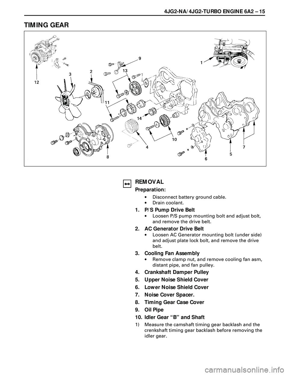
TIMING GEAR
REMOVAL
Preparation:
·Disconnect battery ground cable.
·Drain coolant.
1. P/S Pump Drive Belt
·Loosen P/S pump mounting bolt and adjust bolt,
and remove the drive belt.
2. AC Generator Drive Belt
·Loosen AC Generator mounting bolt (under side)
and adjust plate lock bolt, and remove the drive
belt.
3. Cooling Fan Assembly
·Remove clamp nut, and remove cooling fan asm,
distant pipe, and fan pulley.
4. Crankshaft Damper Pulley
5. Upper Noise Shield Cover
6. Lower Noise Shield Cover
7. Noise Cover Spacer.
8. Timing Gear Case Cover
9. Oil Pipe
10. Idler Gear ÒBÓ and Shaft
1) Measure the camshaft timing gear backlash and the
crenkshaft timing gear backlash before removing the
idler gear.
Page 1622 of 3573
6A2 Ð 20 4JG2-NA/4JG2-TURBO ENGINE
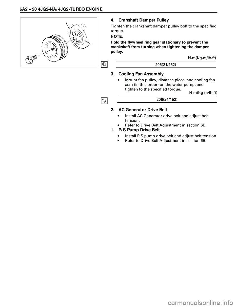
4. Cranshaft Damper Pulley
Tighten the crankshaft damper pulley bolt to the specified
torque.
NOTE:
Hold the flywheel ring gear stationary to prevent the
crankshaft from turning when tightening the damper
pulley.
3. Cooling Fan Assembly
·Mount fan pulley, distance piece, and cooling fan
asm (in this order) on the water pump, and
tighten to the specified torque.
2. AC Generator Drive Belt
·Install AC Generator drive belt and adjust belt
tension.
·Refer to Drive Belt Adjustment in section 6B.
1. P/S Pump Drive Belt
·Install P.S pump drive belt and adjust belt tension.
·Refer to Drive Belt Adjustment in section 6B.
206(21/152)N·m(Kg·m/lb·ft)
206(21/152)N·m(Kg·m/lb·ft)
Page 1629 of 3573
4JG2-NA/4JG2-TURBO ENGINE 6A 2Ð 27
REMOVAL
Preparation
·Remove battery. (two batteries for cold area)
·Disconnect window washer hose, and remove
engine hood.
·Drain coolant.
·Space stand and front right tire.
1. Radiator Hose : Upper
·Disconnect upper radiator hose from engine side.
2. Air Cleaner Cover & Air Duct
3. Intercooler Assembly (4JG2-T Only)
·(Refer to intercooler removal steps in this section)
4. Oil Level Gauge Guide Tube
5. P/S Pump
·Loosen P/S pump fixing bolts and adjusting bolt
and remove two drive belts.
·Remove two fixing bolts (front side). A fixing nut
(rear side) and support P/S pump asm with oil
hoses by tying to body side.
6. A/C Compressor Assembly
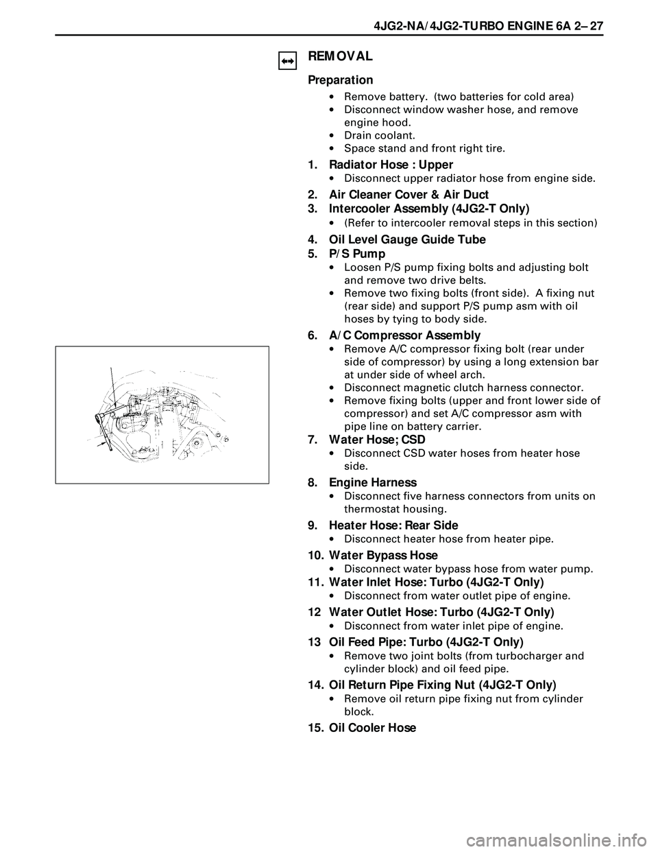
·Remove A/C compressor fixing bolt (rear under
side of compressor) by using a long extension bar
at under side of wheel arch.
·Disconnect magnetic clutch harness connector.
·Remove fixing bolts (upper and front lower side of
compressor) and set A/C compressor asm with
pipe line on battery carrier.
7. Water Hose; CSD
·Disconnect CSD water hoses from heater hose
side.
8. Engine Harness
·Disconnect five harness connectors from units on
thermostat housing.
9. Heater Hose: Rear Side
·Disconnect heater hose from heater pipe.
10. Water Bypass Hose
·Disconnect water bypass hose from water pump.
11. Water Inlet Hose: Turbo (4JG2-T Only)
·Disconnect from water outlet pipe of engine.
12 Water Outlet Hose: Turbo (4JG2-T Only)
·Disconnect from water inlet pipe of engine.
13 Oil Feed Pipe: Turbo (4JG2-T Only)
·Remove two joint bolts (from turbocharger and
cylinder block) and oil feed pipe.
14. Oil Return Pipe Fixing Nut (4JG2-T Only)
·Remove oil return pipe fixing nut from cylinder
block.
15. Oil Cooler Hose
Page 1632 of 3573
6A2 Ð 30 4JG2-NA/4JG2-TURBO ENGINE
13. Oil Feed Pipe: Turbo (4JG2-T Only)
·Tighten joint bolts (cylinder block and turbo
charger side) to the specified torque.
12. Water Outlet Hose: Turbo (4JG2-T Only)
·Connect to water inlet pipe of engine.
11. Water Inlet Hose: Turbo (4JG2-T Only)
·Connect to water outlet pipe.
10. Water Bypass Hose
·Water bypass hose connect to water inlet pipe.
9. Heater Hose
·Connect to heater pipe.
8. Engine Harness
·Connect five harness connecters to units on
thermostat housing.
7. Water Hose: CSD
6. A/C Compressor
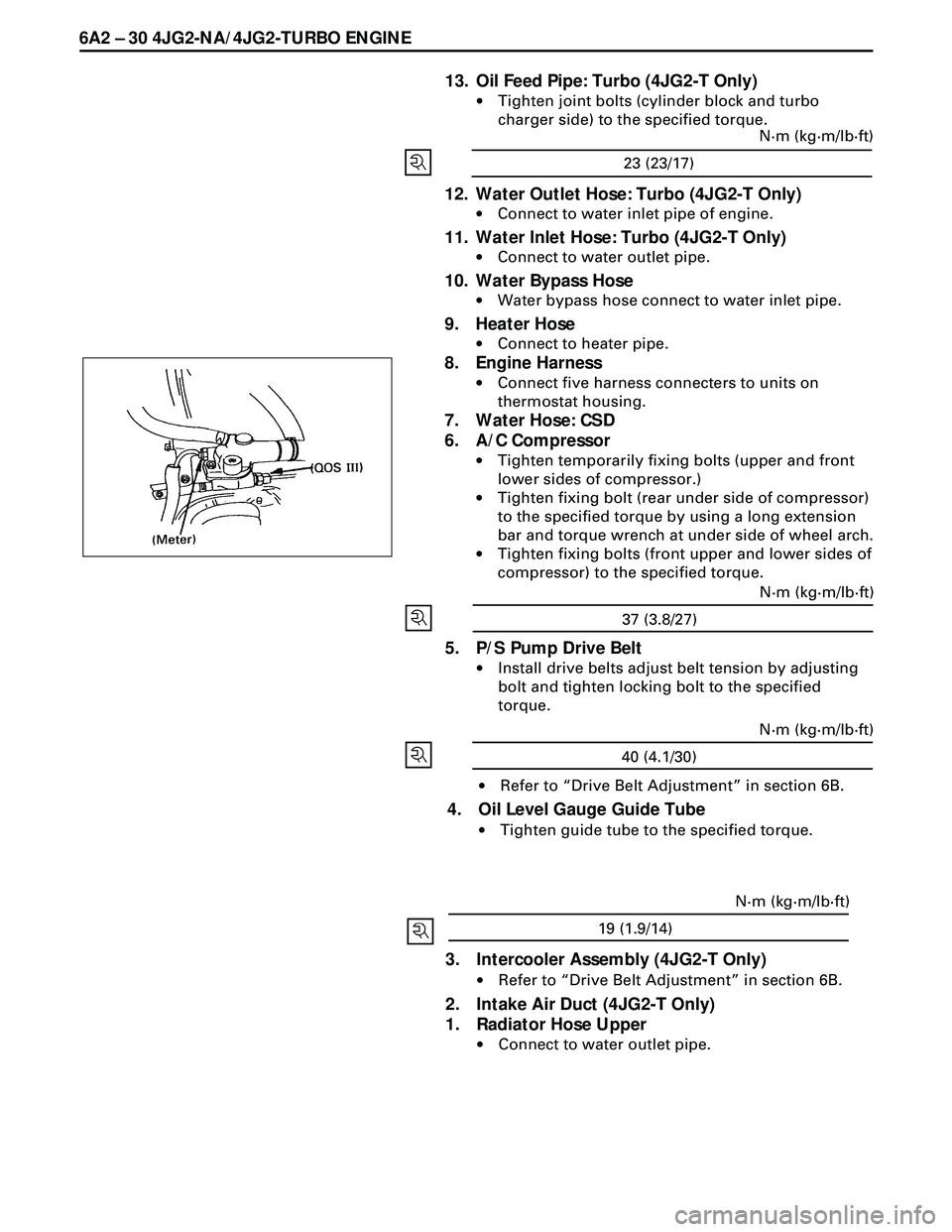
·Tighten temporarily fixing bolts (upper and front
lower sides of compressor.)
·Tighten fixing bolt (rear under side of compressor)
to the specified torque by using a long extension
bar and torque wrench at under side of wheel arch.
·Tighten fixing bolts (front upper and lower sides of
compressor) to the specified torque.
5. P/S Pump Drive Belt
·Install drive belts adjust belt tension by adjusting
bolt and tighten locking bolt to the specified
torque.
·Refer to ÒDrive Belt AdjustmentÓ in section 6B.
4. Oil Level Gauge Guide Tube
·Tighten guide tube to the specified torque.
23 (23/17)N·m (kg·m/lb·ft)
37 (3.8/27)N·m (kg·m/lb·ft)
40 (4.1/30)N·m (kg·m/lb·ft)
19 (1.9/14)N·m (kg·m/lb·ft)
3. Intercooler Assembly (4JG2-T Only)
·Refer to ÒDrive Belt AdjustmentÓ in section 6B.
2. Intake Air Duct (4JG2-T Only)
1. Radiator Hose Upper
·Connect to water outlet pipe.
Page 1651 of 3573
4JG2-NA/4JG2-TURBO ENGINE 6A2 Ð 49
3. Cooling Fan Assembly
·Remove cooling fan asm fixing nuts, cooling fan
asm, fan pulley and center.
4. Radiator Assembly
·Remove bracket and radiator asm.
5. Air Cleaner Cover & Air Duct
6. Intercooler Assembly (4JG2 -T only)
·(Refer to Intercooler removal steps in this section)
7. P/S Pump Drive Belts
·Loosen P/S pump fixing bolts and adjusting bolt
and remove two drive belts.
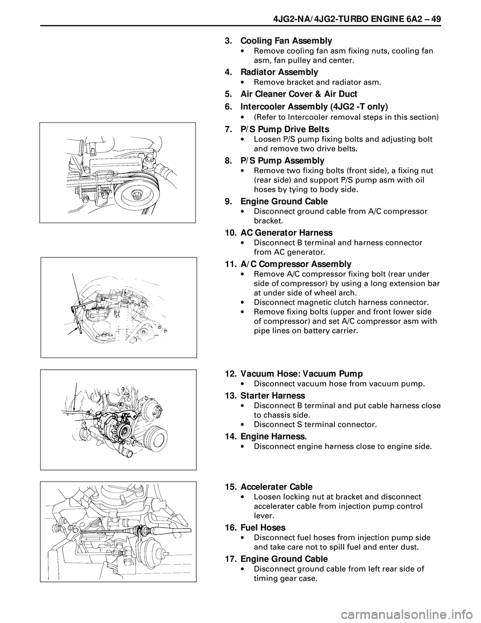
8. P/S Pump Assembly
·Remove two fixing bolts (front side), a fixing nut
(rear side) and support P/S pump asm with oil
hoses by tying to body side.
9. Engine Ground Cable
·Disconnect ground cable from A/C compressor
bracket.
10. AC Generator Harness
·Disconnect B terminal and harness connector
from AC generator.
11. A/C Compressor Assembly
·Remove A/C compressor fixing bolt (rear under
side of compressor) by using a long extension bar
at under side of wheel arch.
·Disconnect magnetic clutch harness connector.
·Remove fixing bolts (upper and front lower side
of compressor) and set A/C compressor asm with
pipe lines on battery carrier.
12. Vacuum Hose: Vacuum Pump
·Disconnect vacuum hose from vacuum pump.
13. Starter Harness
·Disconnect B terminal and put cable harness close
to chassis side.
·Disconnect S terminal connector.
14. Engine Harness.
·Disconnect engine harness close to engine side.
15. Accelerater Cable
·Loosen locking nut at bracket and disconnect
accelerater cable from injection pump control
lever.
16. Fuel Hoses
·Disconnect fuel hoses from injection pump side
and take care not to spill fuel and enter dust.
17. Engine Ground Cable
·Disconnect ground cable from left rear side of
timing gear case.
Page 1654 of 3573
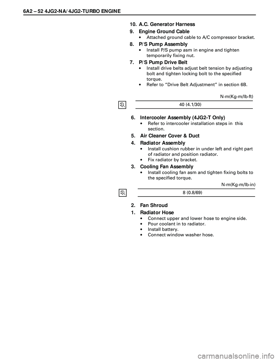
6A2 Ð 52 4JG2-NA/4JG2-TURBO ENGINE
6. Intercooler Assembly (4JG2-T Only)
·Refer to intercooler installation steps in this
section.
5. Air Cleaner Cover & Duct
4. Radiator Assembly
·Install cushion rubber in under left and right part
of radiator and position radiator.
·Fix radiator by bracket.
3. Cooling Fan Assembly
·Install cooling fan asm and tighten fixing bolts to
the specified torque.
2. Fan Shroud
1. Radiator Hose
·Connect upper and lower hose to engine side.
·Pour coolant in to radiator.
·Install battery.
·Connect window washer hose.
10. A.C. Generator Harness
9. Engine Ground Cable
·Attached ground cable to A/C compressor bracket.
8. P/S Pump Assembly
·Install P/S pump asm in engine and tighten
temporarily fixing nut.
7. P/S Pump Drive Belt
·Install drive belts adjust belt tension by adjusting
bolt and tighten locking bolt to the specified
torque.
·Refer to ÒDrive Belt AdjustmentÓ in section 6B.
8 (0.8/69)N·m(Kg·m/lb·in)
40 (4.1/30)N·m(Kg·m/lb·ft)
Page 1655 of 3573
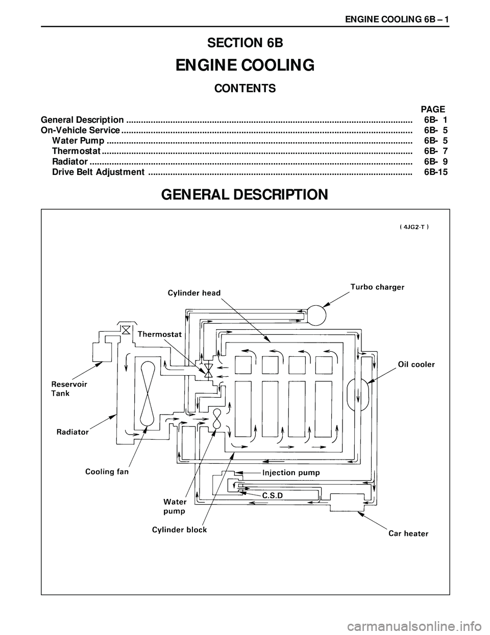
ENGINE COOLING 6B Ð 1
SECTION 6B
ENGINE COOLING
CONTENTS
PAGE
General Description ..................................................................................................................... 6B- 1
On-Vehicle Service ....................................................................................................................... 6B- 5
Water Pump ............................................................................................................................. 6B- 5
Thermostat ............................................................................................................................... 6B- 7
Radiator .................................................................................................................................... 6B- 9
Drive Belt Adjustment ............................................................................................................ 6B-15
GENERAL DESCRIPTION