axle joints ISUZU TROOPER 1998 Service Repair Manual
[x] Cancel search | Manufacturer: ISUZU, Model Year: 1998, Model line: TROOPER, Model: ISUZU TROOPER 1998Pages: 3573, PDF Size: 60.36 MB
Page 29 of 3573
0BÐ2 MAINTENANCE AND LUBRICATION
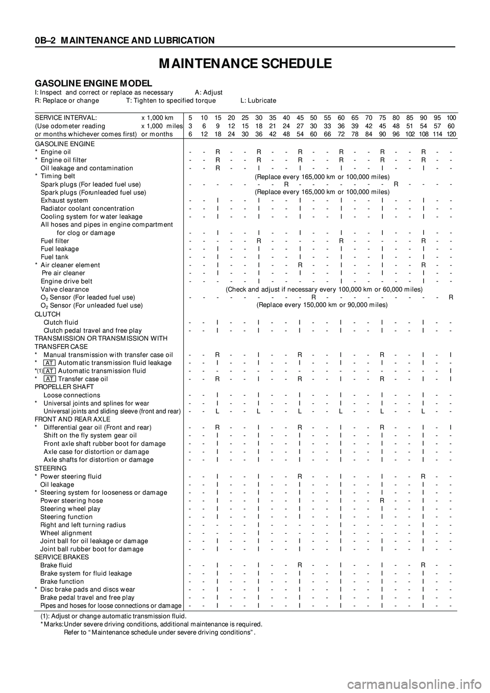
MAINTENANCE SCHEDULE
GASOLINE ENGINE MODELI: Inspect and correct or replace as necessary A: Adjust
R: Replace or change T: Tighten to specified torque L: Lubricate
SERVICE INTERVAL: x 1,000 km
(Use odometer reading x 1,000 miles
or months whichever comes first) or months5
3
610
6
1215
9
1820
12
2425
15
3030
18
3635
21
4240
24
4845
27
5450
30
6055
33
6660
36
7265
39
7870
42
8475
45
9080
48
9685
51
10290
54
10895
57
114100
60
120
GASOLINE ENGINE
* Engine oil
* Engine oil filter
Oil leakage and contamination
* Timing belt
Spark plugs (For leaded fuel use)
Spark plugs (For unleaded fuel use)
Exhaust system
Radiator coolant concentration
Cooling system for water leakage
All hoses and pipes in engine compartment
for clog or damage
Fuel filter
Fuel leakage
Fuel tank
* Air cleaner element
Pre air cleaner
Engine drive belt
Valve clearance
O
2 Sensor (For leaded fuel use)
O
2 Sensor (For unleaded fuel use)-
-
-
-
-
-
-
-
-
-
-
-
-
-
--
-
-
-
-
-
-
-
-
-
-
-
-
-
-R
R
R
-
I
I
I
I
-
I
I
I
I
-
--
-
-
-
-
-
-
-
-
-
-
-
-
-
--
-
-
-
-
-
-
-
-
-
-
-
-
-
-R
R
I
-
I
I
I
I
R
I
I
I
I
I
--
-
-
-
-
-
-
-
-
-
-
-
-
-
--
-
-
R
-
-
-
-
-
-
-
-
-
-
-R
R
I
-
I
I
I
I
-
I
I
R
I
-
--
-
-
-
-
-
-
-
-
-
-
-
-
-
R-
-
-
-
-
-
-
-
-
-
-
-
-
-
-R
R
I
-
I
I
I
I
R
I
I
I
I
I
--
-
-
-
-
-
-
-
-
-
-
-
-
-
--
-
-
-
-
-
-
-
-
-
-
-
-
-
-R
R
I
-
I
I
I
I
-
I
I
I
I
-
--
-
-
R
-
-
-
-
-
-
-
-
-
-
--
-
-
-
-
-
-
-
-
-
-
-
-
-
-R
R
I
-
I
I
I
I
R
I
I
R
I
I
--
-
-
-
-
-
-
-
-
-
-
-
-
-
--
-
-
-
-
-
-
-
-
-
-
-
-
-
R
(Replace every 165,000 km or 100,000 miles)
(Replace every 165,000 km or 100,000 miles)
(Check and adjust if necessary every 100,000 km or 60,000 miles)
(Replace every 150,000 km or 90,000 miles)
CLUTCH
Clutch fluid
Clutch pedal travel and free play
TRANSMISSION OR TRANSMISSION WITH
TRANSFER CASE
* Manual transmission with transfer case oil
* Automatic transmission fluid leakage
*
(1)Automatic transmission fluid
* Transfer case oil
PROPELLER SHAFT
Loose connections
*
Universal joints and splines for wear
Universal joints and sliding sleeve (front and rear)
FRONT AND REAR AXLE
* Differential gear oil (Front and rear)
Shift on the fly system gear oil
Front axle shaft rubber boot for damage
Axle case for distortion or damage
Axle shafts for distortion or damage-
-
-
-
-
-
-
-
-
-
-
-
-
--
-
-
-
-
-
-
-
-
-
-
-
-
-I
I
R
I
-
R
I
I
L
R
I
I
I
I-
-
-
-
-
-
-
-
-
-
-
-
-
--
-
-
-
-
-
-
-
-
-
-
-
-
-I
I
I
I
-
I
I
I
L
I
I
I
I
I-
-
-
-
-
-
-
-
-
-
-
-
-
--
-
-
-
-
-
-
-
-
-
-
-
-
-I
I
R
I
-
R
I
I
L
R
I
I
I
I-
-
-
-
-
-
-
-
-
-
-
-
-
--
-
-
-
-
-
-
-
-
-
-
-
-
-I
I
I
I
-
I
I
I
L
I
I
I
I
I-
-
-
-
-
-
-
-
-
-
-
-
-
--
-
-
-
-
-
-
-
-
-
-
-
-
-I
I
R
I
-
R
I
I
L
R
I
I
I
I-
-
-
-
-
-
-
-
-
-
-
-
-
--
-
-
-
-
-
-
-
-
-
-
-
-
-I
I
I
I
-
I
I
I
L
I
I
I
I
I-
-
-
-
-
-
-
-
-
-
-
-
-
--
-
I
-
I
I
-
-
-
I
-
-
-
-
ATATAT
STEERING
* Power steering fluid
Oil leakage
* Steering system for looseness or damage
Power steering hose
Steering wheel play
Steering function
Right and left turning radius
Wheel alignment
Joint ball for oil leakage or damage
Joint ball rubber boot for damage
SERVICE BRAKES
Brake fluid
Brake system for fluid leakage
Brake function
* Disc brake pads and discs wear
Brake pedal travel and free play
Pipes and hoses for loose connections or damage
-
-
-
-
-
-
-
-
-
-
-
-
-
-
-
--
-
-
-
-
-
-
-
-
-
-
-
-
-
-
-I
I
I
I
I
I
-
-
I
I
I
I
I
I
I
I-
-
-
-
-
-
-
-
-
-
-
-
-
-
-
--
-
-
-
-
-
-
-
-
-
-
-
-
-
-
-I
I
I
I
I
I
I
I
I
I
I
I
I
I
I
I-
-
-
-
-
-
-
-
-
-
-
-
-
-
-
--
-
-
-
-
-
-
-
-
-
-
-
-
-
-
-R
I
I
I
I
I
-
-
I
I
R
I
I
I
I
I-
-
-
-
-
-
-
-
-
-
-
-
-
-
-
--
-
-
-
-
-
-
-
-
-
-
-
-
-
-
-I
I
I
I
I
I
I
I
I
I
I
I
I
I
I
I-
-
-
-
-
-
-
-
-
-
-
-
-
-
-
--
-
-
-
-
-
-
-
-
-
-
-
-
-
-
-I
I
I
R
I
I
-
-
I
I
I
I
I
I
I
I-
-
-
-
-
-
-
-
-
-
-
-
-
-
-
--
-
-
-
-
-
-
-
-
-
-
-
-
-
-
-R
I
I
I
I
I
I
I
I
I
R
I
I
I
I
I-
-
-
-
-
-
-
-
-
-
-
-
-
-
-
--
-
-
-
-
-
-
-
-
-
-
-
-
-
-
-
(1): Adjust or change automatic transmission fluid.
*Marks: Under severe driving conditions, additional maintenance is required.
Refer to “Maintenance schedule under severe driving conditions”.
Page 31 of 3573
0BÐ4 MAINTENANCE AND LUBRICATION
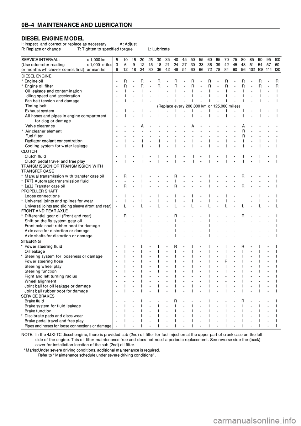
DIESEL ENGINE MODELI: Inspect and correct or replace as necessary A: Adjust
R: Replace or change T: Tighten to specified torque L: Lubricate
SERVICE INTERVAL: x 1,000 km
(Use odometer reading x 1,000 miles
or months whichever comes first) or months5
3
610
6
1215
9
1820
12
2425
15
3030
18
3635
21
4240
24
4845
27
5450
30
6055
33
6660
36
7265
39
7870
42
8475
45
9080
48
9685
51
10290
54
10895
57
114100
60
120
DIESEL ENGINE
* Engine oil
* Engine oil filter
Oil leakage and contamination
Idling speed and acceleration
Fan belt tension and damage
Timing belt
Exhaust system
All hoses and pipes in engine compartment
for clog or damage
Valve clearance
* Air cleaner element
Fuel filter
Radiator coolant concentration
Cooling system for water leakage-
-
-
-
-
-
-
-
-
-
-
-R
R
I
I
I
I
I
-
-
-
I
I-
-
-
-
-
-
-
-
-
-
-
-R
R
I
I
I
I
I
A
-
-
I
I-
-
-
-
-
-
-
-
-
-
-
-R
R
I
I
I
I
I
-
-
-
I
I-
-
-
-
-
-
-
-
-
-
-
-R
R
I
I
I
I
I
-
-
-
I
I-
-
-
-
-
-
-
-
-
-
-
-R
R
I
I
I
I
I
A
-
-
I
I-
-
-
-
-
-
-
-
-
-
-
-R
R
I
I
I
I
I
-
-
-
I
I-
-
-
-
-
-
-
-
-
-
-
-R
R
I
I
I
I
I
-
-
-
I
I-
-
-
-
-
-
-
-
-
-
-
-R
R
I
I
I
I
I
A
R
R
I
I-
-
-
-
-
-
-
-
-
-
-
-R
R
I
I
I
I
I
-
-
-
I
I-
-
-
-
-
-
-
-
-
-
-
-R
R
I
I
I
I
I
-
-
-
I
I
NOTE: In the 4JXI-TC diesel engine, there is provided sub (2nd) oil filter for fuel injection at the upper part of crank case on the left
side of the engine. This oil filter maintenance-free and does not need a periodic replacement. See reverse side the (back)
cover for installation location of the sub (2nd) oil filter.(Replace every 200,000 km or 125,000 miles)
*Marks: Under severe driving conditions, additional maintenance is required.
Refer to “Maintenance schedule under severe driving conditions”. CLUTCH
Clutch fluid
Clutch pedal travel and free play
TRANSMISSION OR TRANSMISSION WITH
TRANSFER CASE
* Manual transmission with transfer case oil
* Automatic transmission fluid
* Transfer case oil
PROPELLER SHAFT
Loose connections
* Universal joints and splines for wear
Universal joints and sliding sleeve (front and rear)FRONT AND REAR AXLE
* Differential gear oil (Front and rear)
Shift on the fly system gear oil
Front axle shaft rubber boot for damage
Axle case for distortion or damage
Axle shafts for distortion or damage-
-
-
-
-
-
-
-
-
-
-
-
-I
I
R
-
R
I
I
L
R
-
-
-
--
-
-
-
-
-
-
-
-
-
-
-
-I
I
I
I
I
I
I
L
I
I
I
I
I-
-
-
-
-
-
-
-
-
-
-
-
-I
I
-
-
-
I
I
L
-
-
-
-
--
-
-
-
-
-
-
-
-
-
-
-
-I
I
R
I
R
I
I
L
R
I
I
I
I-
-
-
-
-
-
-
-
-
-
-
-
-I
I
-
-
-
I
I
L
-
-
-
-
--
-
-
-
-
-
-
-
-
-
-
-
-I
I
I
I
I
I
I
L
I
I
I
I
I-
-
-
-
-
-
-
-
-
-
-
-
-I
I
-
-
-
I
I
L
-
-
-
-
--
-
-
-
-
-
-
-
-
-
-
-
-I
I
R
I
R
I
I
L
R
I
I
I
I-
-
-
-
-
-
-
-
-
-
-
-
-I
I
-
-
-
I
I
L
-
-
-
-
--
-
-
-
-
-
-
-
-
-
-
-
-I
I
I
I
I
I
I
L
I
I
I
I
I
ATAT
STEERING
* Power steering fluid
Oil leakage
* Steering system for looseness or damage
Power steering hose
Steering wheel play
Steering function
Right and left turning radius
Wheel alignment
Joint ball for oil leakage or damage
Joint ball rubber boot for damage
SERVICE BRAKES
Brake fluid
Brake system for fluid leakage
Brake function
* Disc brake pads and discs wear
Brake pedal travel and free play
Pipes and hoses for loose connections or damage
-
-
-
-
-
-
-
-
-
-
-
-
-
-
-
-I
I
I
I
I
I
-
-
I
I
-
I
I
I
I
I-
-
-
-
-
-
-
-
-
-
-
-
-
-
-
-I
I
I
I
I
I
I
I
I
I
I
I
I
I
I
I-
-
-
-
-
-
-
-
-
-
-
-
-
-
-
-I
I
I
I
I
I
-
-
I
I
-
I
I
I
I
I-
-
-
-
-
-
-
-
-
-
-
-
-
-
-
-R
I
I
I
I
I
I
I
I
I
R
I
I
I
I
I-
-
-
-
-
-
-
-
-
-
-
-
-
-
-
-I
I
I
I
I
I
-
-
I
I
-
I
I
I
I
I-
-
-
-
-
-
-
-
-
-
-
-
-
-
-
-I
I
I
I
I
I
I
I
I
I
I
I
I
I
I
I-
-
-
-
-
-
-
-
-
-
-
-
-
-
-
-I
I
I
R
I
I
-
-
I
I
-
I
I
I
I
I-
-
-
-
-
-
-
-
-
-
-
-
-
-
-
-R
I
I
I
I
I
I
I
I
I
R
I
I
I
I
I-
-
-
-
-
-
-
-
-
-
-
-
-
-
-
-I
I
I
I
I
I
-
-
I
I
-
I
I
I
I
I-
-
-
-
-
-
-
-
-
-
-
-
-
-
-
-I
I
I
I
I
I
I
I
I
I
I
I
I
I
I
I
Page 287 of 3573
SERVICE INFORMATION 00 – 5
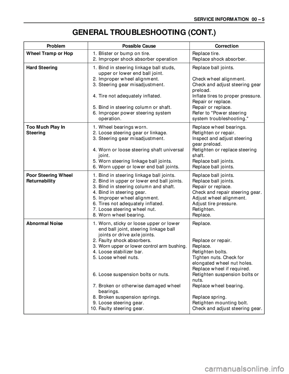
Problem Possible Cause Correction
GENERAL TROUBLESHOOTING (CONT.)
Wheel Tramp or Hop
Hard Steering
Too Much Play In
Steering
Poor Steering Wheel
Returnability
Abnormal Noise1. Blister or bump on tire.
2. Improper shock absorber operation
1. Bind in steering linkage ball studs,
upper or lower end ball joint.
2. Improper wheel alignment.
3. Steering gear misadjustment.
4. Tire not adequately inflated.
5. Bind in steering column or shaft.
6. Improper power steering system
operation.
1. Wheel bearings worn.
2. Loose steering gear or linkage.
3. Steering gear misadjustment.
4. Worn or loose steering shaft universal
joint.
5. Worn steering linkage ball joints.
6. Worn upper or lower end ball joints.
1. Bind in steering linkage ball joints.
2. Bind in upper or lower end ball joints.
3. Bind in steering column and shaft.
4. Bind in steering gear.
5. Improper wheel alignment.
6. Tires not adequately inflated.
7. Loose steering wheel nut.
8. Worn wheel bearing.
1. Worn, sticky or loose upper or lower
end ball joint, steering linkage ball
joints or drive axle joints.
2. Faulty shock absorbers.
3. Worn upper or lower control arm bushing.
4. Loose stabilizer bar.
5. Loose wheel nuts.
6. Loose suspension bolts or nuts.
7. Broken or otherwise damaged wheel
bearings.
8. Broken suspension springs.
9. Loose steering gear.
10. Faulty steering gear.Replace tire.
Replace shock absorber.
Replace ball joints.
Check wheel alignment.
Check and adjust steering gear
preload.
Inflate tires to proper pressure.
Repair or replace.
Repair or replace.
Refer to "Power steering
system troubleshooting."
Replace wheel bearings.
Retighten or repair.
Inspect and adjust steering
gear preload.
Retighten or replace steering
shaft.
Replace ball joints.
Replace ball joints.
Replace ball joints.
Replace ball joints.
Repair or replace.
Check and repair steering gear.
Adjust wheel alignment.
Adjust tire pressure.
Retighten.
Replace.
Replace.
Replace or repair.
Replace.
Retighten bolts.
Tighten nuts. Check for
elongated wheel nut holes.
Replace wheel if required.
Retighten suspension bolts or
nuts.
Replace wheel bearing.
Replace spring.
Retighten mounting bolt.
Check and adjust steering gear.
Page 304 of 3573
2A – 2 FRONT END ALIGNMENT
GENERAL DESCRIPTION
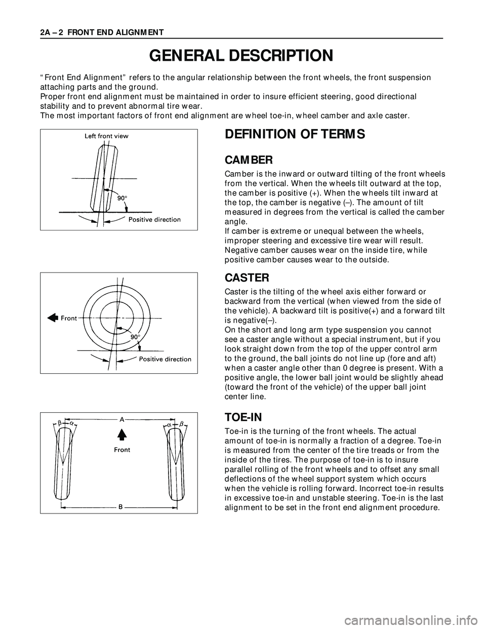
“Front End Alignment” refers to the angular relationship between the front wheels, the front suspension
attaching parts and the ground.
Proper front end alignment must be maintained in order to insure efficient steering, good directional
stability and to prevent abnormal tire wear.
The most important factors of front end alignment are wheel toe-in, wheel camber and axle caster.
DEFINITION OF TERMS
CAMBER
Camber is the inward or outward tilting of the front wheels
from the vertical. When the wheels tilt outward at the top,
the camber is positive (+). When the wheels tilt inward at
the top, the camber is negative (–). The amount of tilt
measured in degrees from the vertical is called the camber
angle.
If camber is extreme or unequal between the wheels,
improper steering and excessive tire wear will result.
Negative camber causes wear on the inside tire, while
positive camber causes wear to the outside.
CASTER
Caster is the tilting of the wheel axis either forward or
backward from the vertical (when viewed from the side of
the vehicle). A backward tilt is positive(+) and a forward tilt
is negative(–).
On the short and long arm type suspension you cannot
see a caster angle without a special instrument, but if you
look straight down from the top of the upper control arm
to the ground, the ball joints do not line up (fore and aft)
when a caster angle other than 0 degree is present. With a
positive angle, the lower ball joint would be slightly ahead
(toward the front of the vehicle) of the upper ball joint
center line.
TOE-IN
Toe-in is the turning of the front wheels. The actual
amount of toe-in is normally a fraction of a degree. Toe-in
is measured from the center of the tire treads or from the
inside of the tires. The purpose of toe-in is to insure
parallel rolling of the front wheels and to offset any small
deflections of the wheel support system which occurs
when the vehicle is rolling forward. Incorrect toe-in results
in excessive toe-in and unstable steering. Toe-in is the last
alignment to be set in the front end alignment procedure.
Page 439 of 3573
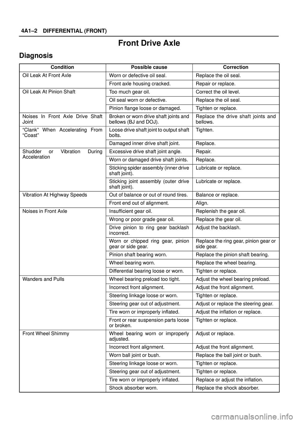
DIFFERENTIAL (FRONT) 4A1±2
Front Drive Axle
Diagnosis
ConditionPossible causeCorrection
Oil Leak At Front AxleWorn or defective oil seal.Replace the oil seal.
Front axle housing cracked.Repair or replace.
Oil Leak At Pinion ShaftToo much gear oil.Correct the oil level.
Oil seal worn or defective.Replace the oil seal.
Pinion flange loose or damaged.Tighten or replace.
Noises In Front Axle Drive Shaft
JointBroken or worn drive shaft joints and
bellows (BJ and DOJ).Replace the drive shaft joints and
bellows.
ªClankº When Accelerating From
ªCoastºLoose drive shaft joint to output shaft
bolts.Tighten.
Damaged inner drive shaft joint.Replace.
Shudder or Vibration During
Acceleration
Excessive drive shaft joint angle.Repair.
AccelerationWorn or damaged drive shaft joints.Replace.
Sticking spider assembly (inner drive
shaft joint).Lubricate or replace.
Sticking joint assembly (outer drive
shaft joint).Lubricate or replace.
Vibration At Highway SpeedsOut of balance or out of round tires.Balance or replace.
Front end out of alignment.Align.
Noises in Front AxleInsufficient gear oil.Replenish the gear oil.
Wrong or poor grade gear oil.Replace the gear oil.
Drive pinion to ring gear backlash
incorrect.Adjust the backlash.
Worn or chipped ring gear, pinion
gear or side gear.Replace the ring gear, pinion gear or
side gear.
Pinion shaft bearing worn.Replace the pinion shaft bearing.
Wheel bearing worn.Replace the wheel bearing.
Differential bearing loose or worn.Tighten or replace.
Wanders and PullsWheel bearing preload too tight.Adjust the wheel bearing preload.
Incorrect front alignment.Adjust the front alignment.
Steering linkage loose or worn.Tighten or replace.
Steering gear out of adjustment.Adjust or replace the steering gear.
Tire worn or improperly inflated.Adjust the inflation or replace.
Front or rear suspension parts loose
or broken.Tighten or replace.
Front Wheel ShimmyWheel bearing worn or improperly
adjusted.Adjust or replace.
Incorrect front alignment.Adjust the front alignment.
Worn ball joint or bush.Replace the ball joint or bush.
Steering linkage loose or worn.Tighten or replace.
Steering gear out of adjustment.Tighten or replace.
Tire worn or improperly inflated.Replace or adjust the inflation.
Shock absorber worn.Replace the shock absorber.
Page 470 of 3573
DIFFERENTIAL (REAR 220mm)
4A2A±3
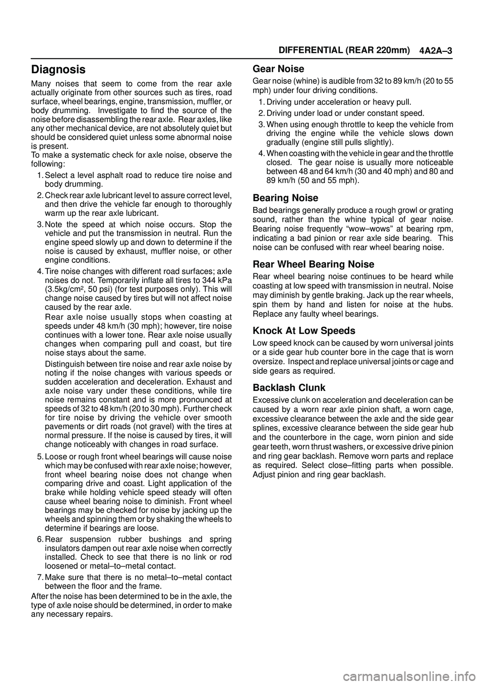
Diagnosis
Many noises that seem to come from the rear axle
actually originate from other sources such as tires, road
surface, wheel bearings, engine, transmission, muffler, or
body drumming. Investigate to find the source of the
noise before disassembling the rear axle. Rear axles, like
any other mechanical device, are not absolutely quiet but
should be considered quiet unless some abnormal noise
is present.
To make a systematic check for axle noise, observe the
following:
1. Select a level asphalt road to reduce tire noise and
body drumming.
2. Check rear axle lubricant level to assure correct level,
and then drive the vehicle far enough to thoroughly
warm up the rear axle lubricant.
3. Note the speed at which noise occurs. Stop the
vehicle and put the transmission in neutral. Run the
engine speed slowly up and down to determine if the
noise is caused by exhaust, muffler noise, or other
engine conditions.
4. Tire noise changes with different road surfaces; axle
noises do not. Temporarily inflate all tires to 344 kPa
(3.5kg/cm
2, 50 psi) (for test purposes only). This will
change noise caused by tires but will not affect noise
caused by the rear axle.
Rear axle noise usually stops when coasting at
speeds under 48 km/h (30 mph); however, tire noise
continues with a lower tone. Rear axle noise usually
changes when comparing pull and coast, but tire
noise stays about the same.
Distinguish between tire noise and rear axle noise by
noting if the noise changes with various speeds or
sudden acceleration and deceleration. Exhaust and
axle noise vary under these conditions, while tire
noise remains constant and is more pronounced at
speeds of 32 to 48 km/h (20 to 30 mph). Further check
for tire noise by driving the vehicle over smooth
pavements or dirt roads (not gravel) with the tires at
normal pressure. If the noise is caused by tires, it will
change noticeably with changes in road surface.
5. Loose or rough front wheel bearings will cause noise
which may be confused with rear axle noise; however,
front wheel bearing noise does not change when
comparing drive and coast. Light application of the
brake while holding vehicle speed steady will often
cause wheel bearing noise to diminish. Front wheel
bearings may be checked for noise by jacking up the
wheels and spinning them or by shaking the wheels to
determine if bearings are loose.
6. Rear suspension rubber bushings and spring
insulators dampen out rear axle noise when correctly
installed. Check to see that there is no link or rod
loosened or metal±to±metal contact.
7. Make sure that there is no metal±to±metal contact
between the floor and the frame.
After the noise has been determined to be in the axle, the
type of axle noise should be determined, in order to make
any necessary repairs.
Gear Noise
Gear noise (whine) is audible from 32 to 89 km/h (20 to 55
mph) under four driving conditions.
1. Driving under acceleration or heavy pull.
2. Driving under load or under constant speed.
3. When using enough throttle to keep the vehicle from
driving the engine while the vehicle slows down
gradually (engine still pulls slightly).
4. When coasting with the vehicle in gear and the throttle
closed. The gear noise is usually more noticeable
between 48 and 64 km/h (30 and 40 mph) and 80 and
89 km/h (50 and 55 mph).
Bearing Noise
Bad bearings generally produce a rough growl or grating
sound, rather than the whine typical of gear noise.
Bearing noise frequently ªwow±wowsº at bearing rpm,
indicating a bad pinion or rear axle side bearing. This
noise can be confused with rear wheel bearing noise.
Rear Wheel Bearing Noise
Rear wheel bearing noise continues to be heard while
coasting at low speed with transmission in neutral. Noise
may diminish by gentle braking. Jack up the rear wheels,
spin them by hand and listen for noise at the hubs.
Replace any faulty wheel bearings.
Knock At Low Speeds
Low speed knock can be caused by worn universal joints
or a side gear hub counter bore in the cage that is worn
oversize. Inspect and replace universal joints or cage and
side gears as required.
Backlash Clunk
Excessive clunk on acceleration and deceleration can be
caused by a worn rear axle pinion shaft, a worn cage,
excessive clearance between the axle and the side gear
splines, excessive clearance between the side gear hub
and the counterbore in the cage, worn pinion and side
gear teeth, worn thrust washers, or excessive drive pinion
and ring gear backlash. Remove worn parts and replace
as required. Select close±fitting parts when possible.
Adjust pinion and ring gear backlash.
Page 506 of 3573
DIFFERENTIAL (REAR 244mm)
4A2B±3
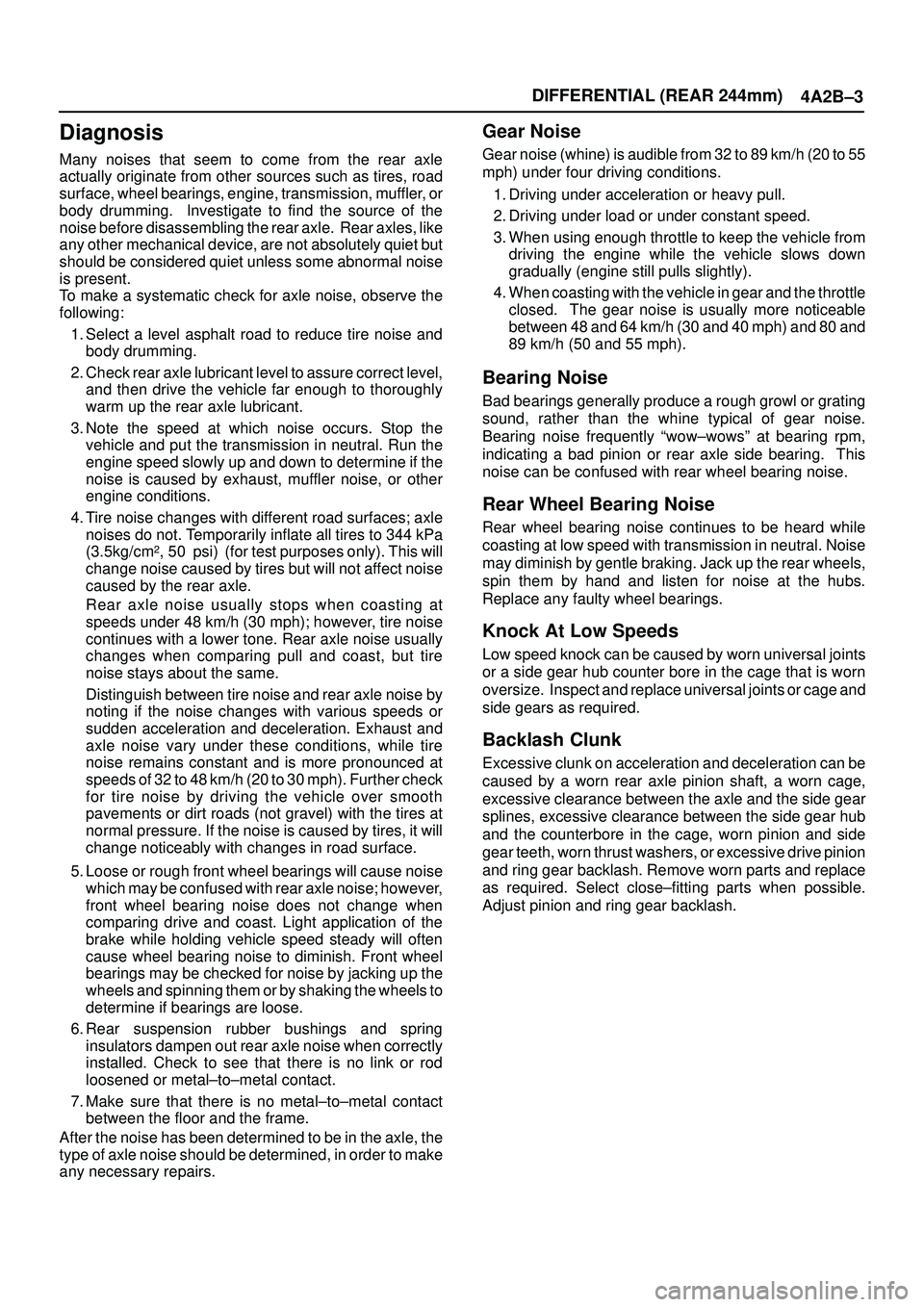
Diagnosis
Many noises that seem to come from the rear axle
actually originate from other sources such as tires, road
surface, wheel bearings, engine, transmission, muffler, or
body drumming. Investigate to find the source of the
noise before disassembling the rear axle. Rear axles, like
any other mechanical device, are not absolutely quiet but
should be considered quiet unless some abnormal noise
is present.
To make a systematic check for axle noise, observe the
following:
1. Select a level asphalt road to reduce tire noise and
body drumming.
2. Check rear axle lubricant level to assure correct level,
and then drive the vehicle far enough to thoroughly
warm up the rear axle lubricant.
3. Note the speed at which noise occurs. Stop the
vehicle and put the transmission in neutral. Run the
engine speed slowly up and down to determine if the
noise is caused by exhaust, muffler noise, or other
engine conditions.
4. Tire noise changes with different road surfaces; axle
noises do not. Temporarily inflate all tires to 344 kPa
(3.5kg/cm
2, 50 psi) (for test purposes only). This will
change noise caused by tires but will not affect noise
caused by the rear axle.
Rear axle noise usually stops when coasting at
speeds under 48 km/h (30 mph); however, tire noise
continues with a lower tone. Rear axle noise usually
changes when comparing pull and coast, but tire
noise stays about the same.
Distinguish between tire noise and rear axle noise by
noting if the noise changes with various speeds or
sudden acceleration and deceleration. Exhaust and
axle noise vary under these conditions, while tire
noise remains constant and is more pronounced at
speeds of 32 to 48 km/h (20 to 30 mph). Further check
for tire noise by driving the vehicle over smooth
pavements or dirt roads (not gravel) with the tires at
normal pressure. If the noise is caused by tires, it will
change noticeably with changes in road surface.
5. Loose or rough front wheel bearings will cause noise
which may be confused with rear axle noise; however,
front wheel bearing noise does not change when
comparing drive and coast. Light application of the
brake while holding vehicle speed steady will often
cause wheel bearing noise to diminish. Front wheel
bearings may be checked for noise by jacking up the
wheels and spinning them or by shaking the wheels to
determine if bearings are loose.
6. Rear suspension rubber bushings and spring
insulators dampen out rear axle noise when correctly
installed. Check to see that there is no link or rod
loosened or metal±to±metal contact.
7. Make sure that there is no metal±to±metal contact
between the floor and the frame.
After the noise has been determined to be in the axle, the
type of axle noise should be determined, in order to make
any necessary repairs.
Gear Noise
Gear noise (whine) is audible from 32 to 89 km/h (20 to 55
mph) under four driving conditions.
1. Driving under acceleration or heavy pull.
2. Driving under load or under constant speed.
3. When using enough throttle to keep the vehicle from
driving the engine while the vehicle slows down
gradually (engine still pulls slightly).
4. When coasting with the vehicle in gear and the throttle
closed. The gear noise is usually more noticeable
between 48 and 64 km/h (30 and 40 mph) and 80 and
89 km/h (50 and 55 mph).
Bearing Noise
Bad bearings generally produce a rough growl or grating
sound, rather than the whine typical of gear noise.
Bearing noise frequently ªwow±wowsº at bearing rpm,
indicating a bad pinion or rear axle side bearing. This
noise can be confused with rear wheel bearing noise.
Rear Wheel Bearing Noise
Rear wheel bearing noise continues to be heard while
coasting at low speed with transmission in neutral. Noise
may diminish by gentle braking. Jack up the rear wheels,
spin them by hand and listen for noise at the hubs.
Replace any faulty wheel bearings.
Knock At Low Speeds
Low speed knock can be caused by worn universal joints
or a side gear hub counter bore in the cage that is worn
oversize. Inspect and replace universal joints or cage and
side gears as required.
Backlash Clunk
Excessive clunk on acceleration and deceleration can be
caused by a worn rear axle pinion shaft, a worn cage,
excessive clearance between the axle and the side gear
splines, excessive clearance between the side gear hub
and the counterbore in the cage, worn pinion and side
gear teeth, worn thrust washers, or excessive drive pinion
and ring gear backlash. Remove worn parts and replace
as required. Select close±fitting parts when possible.
Adjust pinion and ring gear backlash.
Page 667 of 3573
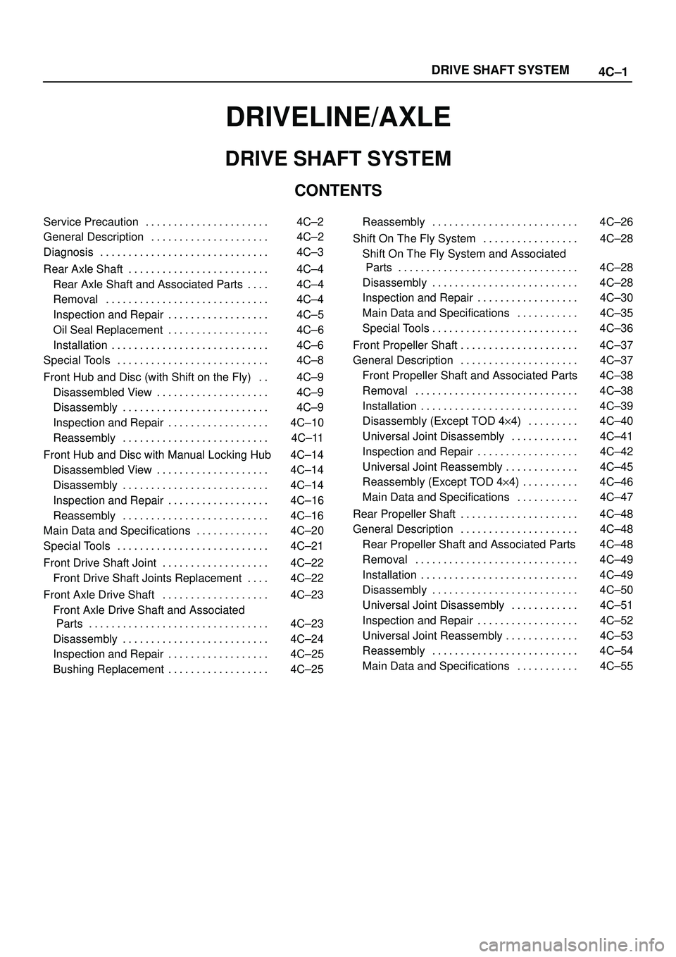
4C±1 DRIVE SHAFT SYSTEM
DRIVELINE/AXLE
DRIVE SHAFT SYSTEM
CONTENTS
Service Precaution 4C±2. . . . . . . . . . . . . . . . . . . . . .
General Description 4C±2. . . . . . . . . . . . . . . . . . . . .
Diagnosis 4C±3. . . . . . . . . . . . . . . . . . . . . . . . . . . . . .
Rear Axle Shaft 4C±4. . . . . . . . . . . . . . . . . . . . . . . . .
Rear Axle Shaft and Associated Parts 4C±4. . . .
Removal 4C±4. . . . . . . . . . . . . . . . . . . . . . . . . . . . .
Inspection and Repair 4C±5. . . . . . . . . . . . . . . . . .
Oil Seal Replacement 4C±6. . . . . . . . . . . . . . . . . .
Installation 4C±6. . . . . . . . . . . . . . . . . . . . . . . . . . . .
Special Tools 4C±8. . . . . . . . . . . . . . . . . . . . . . . . . . .
Front Hub and Disc (with Shift on the Fly) 4C±9. .
Disassembled View 4C±9. . . . . . . . . . . . . . . . . . . .
Disassembly 4C±9. . . . . . . . . . . . . . . . . . . . . . . . . .
Inspection and Repair 4C±10. . . . . . . . . . . . . . . . . .
Reassembly 4C±11. . . . . . . . . . . . . . . . . . . . . . . . . .
Front Hub and Disc with Manual Locking Hub 4C±14
Disassembled View 4C±14. . . . . . . . . . . . . . . . . . . .
Disassembly 4C±14. . . . . . . . . . . . . . . . . . . . . . . . . .
Inspection and Repair 4C±16. . . . . . . . . . . . . . . . . .
Reassembly 4C±16. . . . . . . . . . . . . . . . . . . . . . . . . .
Main Data and Specifications 4C±20. . . . . . . . . . . . .
Special Tools 4C±21. . . . . . . . . . . . . . . . . . . . . . . . . . .
Front Drive Shaft Joint 4C±22. . . . . . . . . . . . . . . . . . .
Front Drive Shaft Joints Replacement 4C±22. . . .
Front Axle Drive Shaft 4C±23. . . . . . . . . . . . . . . . . . .
Front Axle Drive Shaft and Associated
Parts 4C±23. . . . . . . . . . . . . . . . . . . . . . . . . . . . . . . .
Disassembly 4C±24. . . . . . . . . . . . . . . . . . . . . . . . . .
Inspection and Repair 4C±25. . . . . . . . . . . . . . . . . .
Bushing Replacement 4C±25. . . . . . . . . . . . . . . . . . Reassembly 4C±26. . . . . . . . . . . . . . . . . . . . . . . . . .
Shift On The Fly System 4C±28. . . . . . . . . . . . . . . . .
Shift On The Fly System and Associated
Parts 4C±28. . . . . . . . . . . . . . . . . . . . . . . . . . . . . . . .
Disassembly 4C±28. . . . . . . . . . . . . . . . . . . . . . . . . .
Inspection and Repair 4C±30. . . . . . . . . . . . . . . . . .
Main Data and Specifications 4C±35. . . . . . . . . . .
Special Tools 4C±36. . . . . . . . . . . . . . . . . . . . . . . . . .
Front Propeller Shaft 4C±37. . . . . . . . . . . . . . . . . . . . .
General Description 4C±37. . . . . . . . . . . . . . . . . . . . .
Front Propeller Shaft and Associated Parts 4C±38
Removal 4C±38. . . . . . . . . . . . . . . . . . . . . . . . . . . . .
Installation 4C±39. . . . . . . . . . . . . . . . . . . . . . . . . . . .
Disassembly (Except TOD 4y4) 4C±40. . . . . . . . .
Universal Joint Disassembly 4C±41. . . . . . . . . . . .
Inspection and Repair 4C±42. . . . . . . . . . . . . . . . . .
Universal Joint Reassembly 4C±45. . . . . . . . . . . . .
Reassembly (Except TOD 4y4) 4C±46. . . . . . . . . .
Main Data and Specifications 4C±47. . . . . . . . . . .
Rear Propeller Shaft 4C±48. . . . . . . . . . . . . . . . . . . . .
General Description 4C±48. . . . . . . . . . . . . . . . . . . . .
Rear Propeller Shaft and Associated Parts 4C±48
Removal 4C±49. . . . . . . . . . . . . . . . . . . . . . . . . . . . .
Installation 4C±49. . . . . . . . . . . . . . . . . . . . . . . . . . . .
Disassembly 4C±50. . . . . . . . . . . . . . . . . . . . . . . . . .
Universal Joint Disassembly 4C±51. . . . . . . . . . . .
Inspection and Repair 4C±52. . . . . . . . . . . . . . . . . .
Universal Joint Reassembly 4C±53. . . . . . . . . . . . .
Reassembly 4C±54. . . . . . . . . . . . . . . . . . . . . . . . . .
Main Data and Specifications 4C±55. . . . . . . . . . .
Page 668 of 3573
4C±2
DRIVE SHAFT SYSTEM
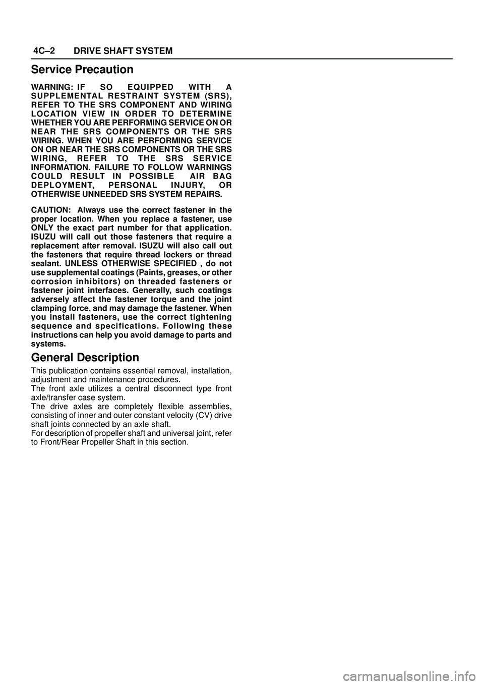
Service Precaution
WARNING: I F S O E Q U IPPED WITH A
SUPPLEMENTAL RESTRAINT SYSTEM (SRS),
REFER TO THE SRS COMPONENT AND WIRING
LOCATION VIEW IN ORDER TO DETERMINE
WHETHER YOU ARE PERFORMING SERVICE ON OR
NEAR THE SRS COMPONENTS OR THE SRS
WIRING. WHEN YOU ARE PERFORMING SERVICE
ON OR NEAR THE SRS COMPONENTS OR THE SRS
WIRING, REFER TO THE SRS SERVICE
INFORMATION. FAILURE TO FOLLOW WARNINGS
COULD RESULT IN POSSIBLE AIR BAG
DEPLOYMENT, PERSONAL INJURY, OR
OTHERWISE UNNEEDED SRS SYSTEM REPAIRS.
CAUTION: Always use the correct fastener in the
proper location. When you replace a fastener, use
ONLY the exact part number for that application.
ISUZU will call out those fasteners that require a
replacement after removal. ISUZU will also call out
the fasteners that require thread lockers or thread
sealant. UNLESS OTHERWISE SPECIFIED , do not
use supplemental coatings (Paints, greases, or other
corrosion inhibitors) on threaded fasteners or
fastener joint interfaces. Generally, such coatings
adversely affect the fastener torque and the joint
clamping force, and may damage the fastener. When
you install fasteners, use the correct tightening
sequence and specifications. Following these
instructions can help you avoid damage to parts and
systems.
General Description
This publication contains essential removal, installation,
adjustment and maintenance procedures.
The front axle utilizes a central disconnect type front
axle/transfer case system.
The drive axles are completely flexible assemblies,
consisting of inner and outer constant velocity (CV) drive
shaft joints connected by an axle shaft.
For description of propeller shaft and universal joint, refer
to Front/Rear Propeller Shaft in this section.
Page 669 of 3573
4C±3 DRIVE SHAFT SYSTEM
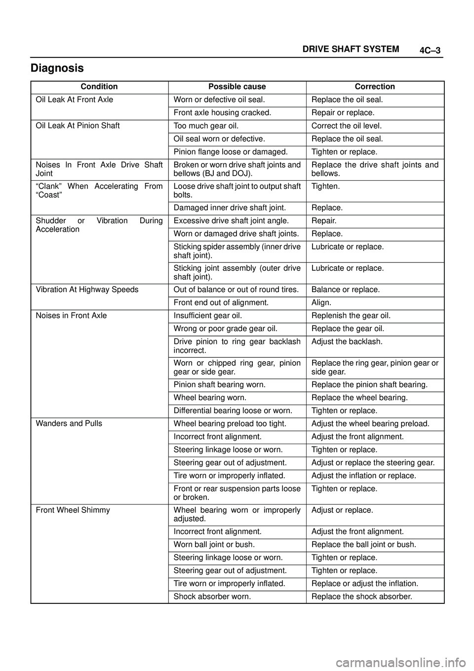
Diagnosis
ConditionPossible causeCorrection
Oil Leak At Front AxleWorn or defective oil seal.Replace the oil seal.
Front axle housing cracked.Repair or replace.
Oil Leak At Pinion ShaftToo much gear oil.Correct the oil level.
Oil seal worn or defective.Replace the oil seal.
Pinion flange loose or damaged.Tighten or replace.
Noises In Front Axle Drive Shaft
JointBroken or worn drive shaft joints and
bellows (BJ and DOJ).Replace the drive shaft joints and
bellows.
ªClankº When Accelerating From
ªCoastºLoose drive shaft joint to output shaft
bolts.Tighten.
Damaged inner drive shaft joint.Replace.
Shudder or Vibration During
Acceleration
Excessive drive shaft joint angle.Repair.
AccelerationWorn or damaged drive shaft joints.Replace.
Sticking spider assembly (inner drive
shaft joint).Lubricate or replace.
Sticking joint assembly (outer drive
shaft joint).Lubricate or replace.
Vibration At Highway SpeedsOut of balance or out of round tires.Balance or replace.
Front end out of alignment.Align.
Noises in Front AxleInsufficient gear oil.Replenish the gear oil.
Wrong or poor grade gear oil.Replace the gear oil.
Drive pinion to ring gear backlash
incorrect.Adjust the backlash.
Worn or chipped ring gear, pinion
gear or side gear.Replace the ring gear, pinion gear or
side gear.
Pinion shaft bearing worn.Replace the pinion shaft bearing.
Wheel bearing worn.Replace the wheel bearing.
Differential bearing loose or worn.Tighten or replace.
Wanders and PullsWheel bearing preload too tight.Adjust the wheel bearing preload.
Incorrect front alignment.Adjust the front alignment.
Steering linkage loose or worn.Tighten or replace.
Steering gear out of adjustment.Adjust or replace the steering gear.
Tire worn or improperly inflated.Adjust the inflation or replace.
Front or rear suspension parts loose
or broken.Tighten or replace.
Front Wheel ShimmyWheel bearing worn or improperly
adjusted.Adjust or replace.
Incorrect front alignment.Adjust the front alignment.
Worn ball joint or bush.Replace the ball joint or bush.
Steering linkage loose or worn.Tighten or replace.
Steering gear out of adjustment.Tighten or replace.
Tire worn or improperly inflated.Replace or adjust the inflation.
Shock absorber worn.Replace the shock absorber.