jack points ISUZU TROOPER 1998 Service Repair Manual
[x] Cancel search | Manufacturer: ISUZU, Model Year: 1998, Model line: TROOPER, Model: ISUZU TROOPER 1998Pages: 3573, PDF Size: 60.36 MB
Page 16 of 3573

GENERAL REPAIR INSTRUCTIONS
1. Park the vehicle on level ground and chock the
front or rear wheels before lifting the vehicle.
2. Use covers on the vehicle body, seats, and
floor to prevent damage and/or
contaminations.
3. Disconnect the grounding cable from the
battery before performing service operations.
This will prevent cable damage or burning due
to shortcircuiting.
4. Raise the vehicle with a jack set against the
recommended lifting points (see ÒLifting
instructionsÓ in this section).
5. Support the vehicle on chassis stands.
6. Handle brake fluid and antifreeze solution with
great care.
Spilling these liquids on painted surfaces will
damage the paint.
7. The use of the proper tool(s) and special tool(s)
where specified is essential to efficient,
reliable, and safe service operations.
8. Always use genuine ISUZU replacement parts.
9. Discard used cotter pins, gasket, plastic clips,
O-rings, oil seals, lock washers, and self-
locking nuts at disassembly.
Normal function of these parts cannot be
guaranteed if they are reused.
10. Keep the disassembled parts neatly in groups.
This will facilitate smooth and correct
reassembly.11. Keep fixing nuts and bolts separate.
Fixing nuts and bolts vary in hardness and
design according to installation positions.
12. Clean all parts before inspection or
reassembly.
13. Clean the oil ports and other openings with
compressed air to make certain that they are
free of dirt and obstructions.
14. Lubricate the rotating and sliding faces of all
moving parts with oil or grease before
installation.
15. Use the recommended liquid gasket to prevent
leakage.
16. Carefully observe all nut and bolt torque
specifications.
17. When service operation is completed, make a
final check to be sure service has been done
properly and problem has been corrected.
18. When removing or replacing parts that require
refrigerant to be discharged from the air
conditioning system, be sure to use the
following tools to recover and recycle the
Refrigerant-134a (R-134a).
For 134a:
Use the R-134a Refrigerant Recovery/Recovery/
Recycling/Recharging/System (ACR
4) or its
equivalent to prevent the discharge of
refrigerant into the air.
0AÐ2 GENERAL INFORMATION
Page 22 of 3573

0AÐ8 GENERAL INFORMATION
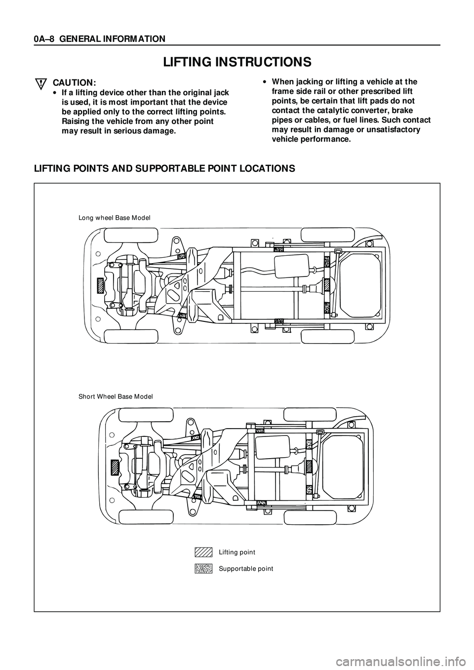
LIFTING INSTRUCTIONS
CAUTION:
·If a lifting device other than the original jack
is used, it is most important that the device
be applied only to the correct lifting points.
Raising the vehicle from any other point
may result in serious damage.
·When jacking or lifting a vehicle at the
frame side rail or other prescribed lift
points, be certain that lift pads do not
contact the catalytic converter, brake
pipes or cables, or fuel lines. Such contact
may result in damage or unsatisfactory
vehicle performance.
LIFTING POINTS AND SUPPORTABLE POINT LOCATIONS
Long wheel Base Model
Short Wheel Base Model
Lifting point
Supportable point
Page 770 of 3573

4D2±3 TRANSFER CASE (TOD)
6. Disconnect the wiring harness connector and shift
lock cable and then remove the front console.
7. Remove the selector lever assembly and put it aside.
8. Remove the transfer control lever.
9. Disconnect the breather hose.
10. Remove the left front exhaust pipe fixing bolts and
nuts, and put the exhaust pipe aside.
11. Remove the left seat belt tension rod and put the rear
proper shaft aside.
260RW006
12. Remove the silencer.
13. Disconnect the transfer connector from the top of the
transfer case.
14. Disconnect the speed sensor harness connector.
15. Remove the fuel pipe clip fixing bolt on the transfer
case.
16. Support the transmission with a jack.
17. Remove the seven bolts from the transfer case.
18. Remove transfer case assembly.
Installation
To install, follow the removal steps in the reverse order,
nothing the following points:
1. Apply a thin coat of grease (Besco L2) or equivalent to
the input shaft spline.
261RW024
2. Mount the transfer case.
Page 2442 of 3573

MUA MODEL 7B1 – 51
REMOVAL AND INSTALLATION
Read this Section carefully before performing any removal and installation procedure. This Section gives
you important points as well as the order of operation. Be sure that you understand everything in this
Section before you begin.
Important Operations – Removal
Battery Cable
Disconnect the negative (–) cable from the battery
terminal.
Engine Hood
Apply setting marks to the engine hood and the engine
hood hinges before removing the engine hood.
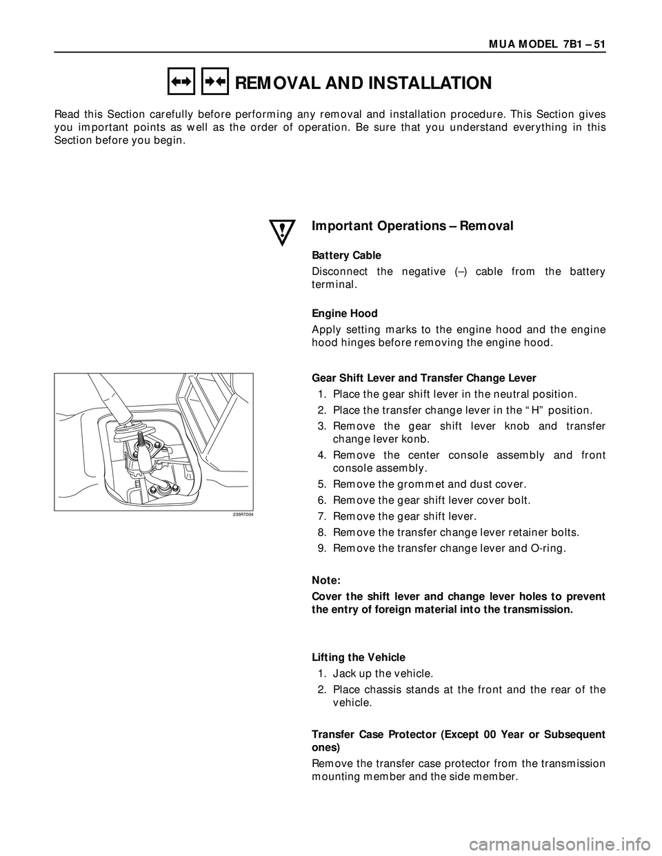
Gear Shift Lever and Transfer Change Lever
1. Place the gear shift lever in the neutral position.
2. Place the transfer change lever in the “H” position.
3. Remove the gear shift lever knob and transfer
change lever konb.
4. Remove the center console assembly and front
console assembly.
5. Remove the grommet and dust cover.
6. Remove the gear shift lever cover bolt.
7. Remove the gear shift lever.
8. Remove the transfer change lever retainer bolts.
9. Remove the transfer change lever and O-ring.
Note:
Cover the shift lever and change lever holes to prevent
the entry of foreign material into the transmission.
Lifting the Vehicle
1. Jack up the vehicle.
2. Place chassis stands at the front and the rear of the
vehicle.
Transfer Case Protector (Except 00 Year or Subsequent
ones)
Remove the transfer case protector from the transmission
mounting member and the side member.
235RT004