engine JAGUAR S TYPE 1999 1.G Powertrain Manual
[x] Cancel search | Manufacturer: JAGUAR, Model Year: 1999, Model line: S TYPE, Model: JAGUAR S TYPE 1999 1.GPages: 75, PDF Size: 3.4 MB
Page 15 of 75
V6 Engine
10
D.303.1204
CAMSHAFT DRIVE
D.303.1204
AJ-V6/AJ28
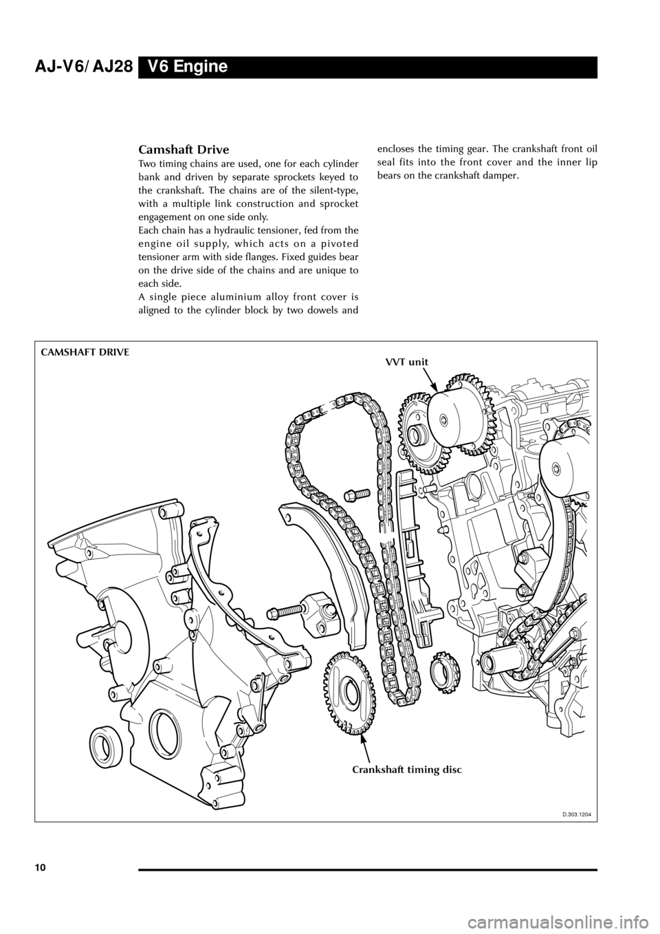
Camshaft Drive
Two timing chains are used, one for each cylinder
bank and driven by separate sprockets keyed to
the crankshaft. The chains are of the silent-type,
with a multiple link construction and sprocket
engagement on one side only.
Each chain has a hydraulic tensioner, fed from the
engine oil supply, which acts on a pivoted
tensioner arm with side flanges. Fixed guides bear
on the drive side of the chains and are unique to
each side.
A single piece aluminium alloy front cover is
aligned to the cylinder block by two dowels andencloses the timing gear. The crankshaft front oil
seal fits into the front cover and the inner lip
bears on the crankshaft damper.
Crankshaft timing disc
VVT unit
Page 16 of 75
V6 EngineAJ-V6/AJ28
11
D.303.1220
IGNITION COIL COVERIgnition Coil Cover
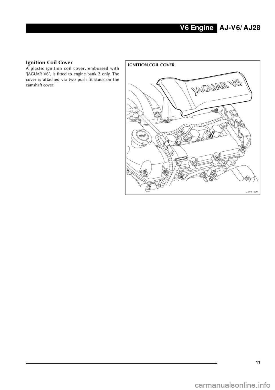
A plastic ignition coil cover, embossed with
ÔJAGUAR V6Õ, is fitted to engine bank 2 only. The
cover is attached via two push fit studs on the
camshaft cover.
D.303.1220
Page 17 of 75
V6 Engine AJ-V6/AJ28
12
D.303.1216
Exhaust Manifold
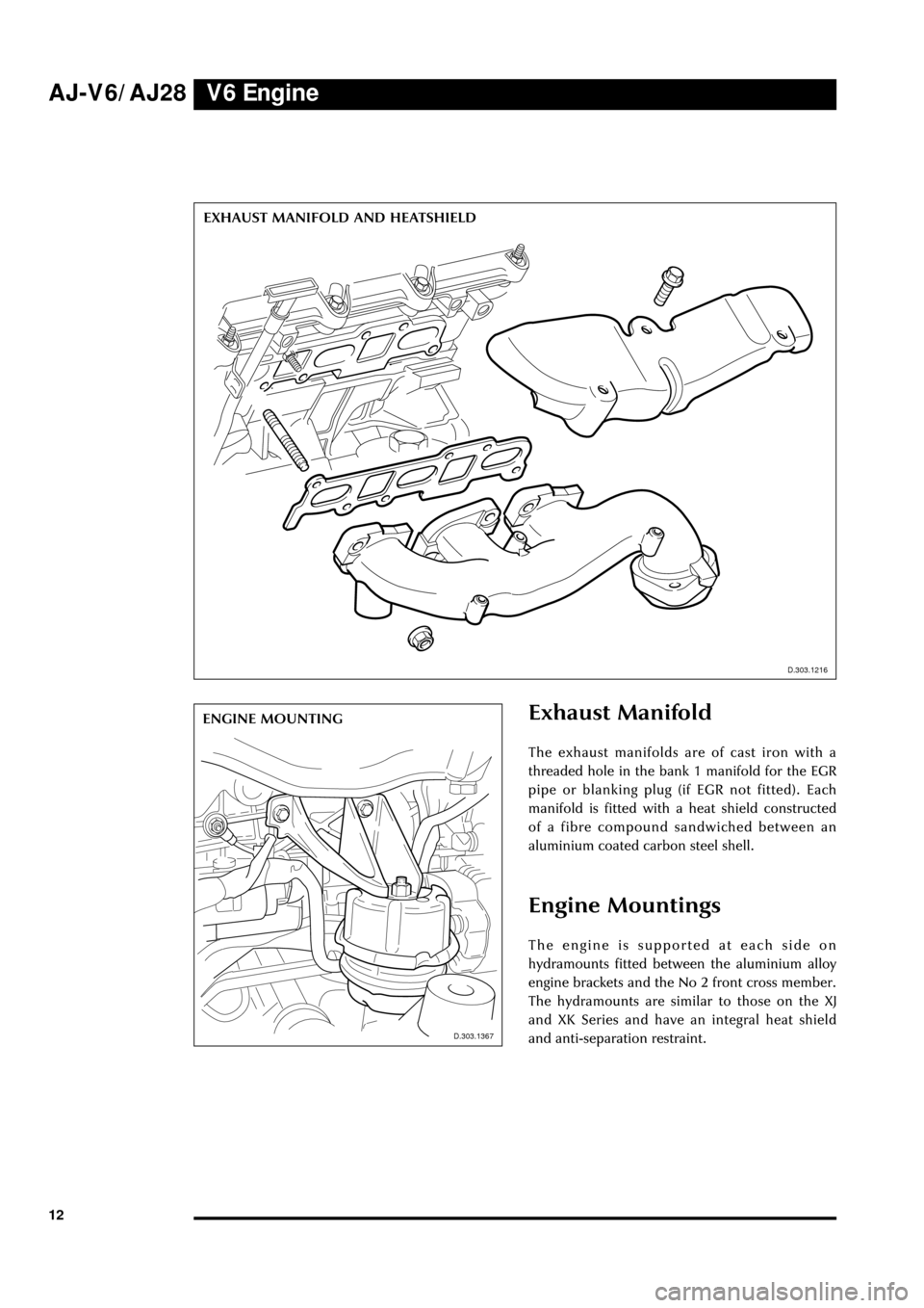
The exhaust manifolds are of cast iron with a
threaded hole in the bank 1 manifold for the EGR
pipe or blanking plug (if EGR not fitted). Each
manifold is fitted with a heat shield constructed
of a fibre compound sandwiched between an
aluminium coated carbon steel shell.
Engine Mountings
The engine is supported at each side on
hydramounts fitted between the aluminium alloy
engine brackets and the No 2 front cross member.
The hydramounts are similar to those on the XJ
and XK Series and have an integral heat shield
and anti-separation restraint. EXHAUST MANIFOLD AND HEATSHIELD
D.303.1216
D.303.1367D.303.1367
ENGINE MOUNTING
Page 18 of 75
V6 EngineAJ-V6/AJ28
13
Oil Distribution
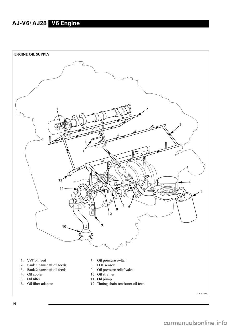
(see illustration on page 14)
Oil distribution within the block and cylinder
heads is similar to that of the V8 engine, the main
differences being in the filter and cooler
arrangement and the method of supplying the
VVT system.
Oil is drawn from the sump through the strainer
by the crankshaft driven pump, passes through
the externally mounted filter and oil cooler and
returns to the block. Distribution is via the main
gallery and crankshaft oilways to the lower
crankcase components and via branch feeds to
the chain tensioners and then cylinder head
components. Extra oilways in the cylinder heads
provide a built-in feed for the VVT components
(see VVT section).
Oil Pump
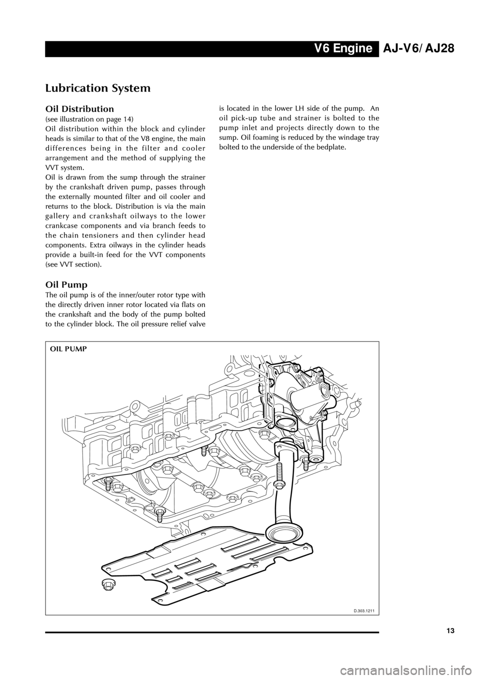
The oil pump is of the inner/outer rotor type with
the directly driven inner rotor located via flats on
the crankshaft and the body of the pump bolted
to the cylinder block. The oil pressure relief valveis located in the lower LH side of the pump. An
oil pick-up tube and strainer is bolted to the
pump inlet and projects directly down to the
sump. Oil foaming is reduced by the windage tray
bolted to the underside of the bedplate.
D.303.1211
Lubrication System
OIL PUMP
D.303.1211
Page 19 of 75
V6 Engine
14
J.303.1289
ENGINE OIL SUPPLY
J.303.1289
AJ-V6/AJ28
1. VVT oil feed
2. Bank 1 camshaft oil feeds
3. Bank 2 camshaft oil feeds
4. Oil cooler
5. Oil filter
6. Oil filter adaptor7. Oil pressure switch
8. EOT sensor
9. Oil pressure relief valve
10. Oil strainer
11. Oil pump
12. Timing chain tensioner oil feed
1
21
3
4
5
678
12
910
11
12
Page 20 of 75
V6 EngineAJ-V6/AJ28
15
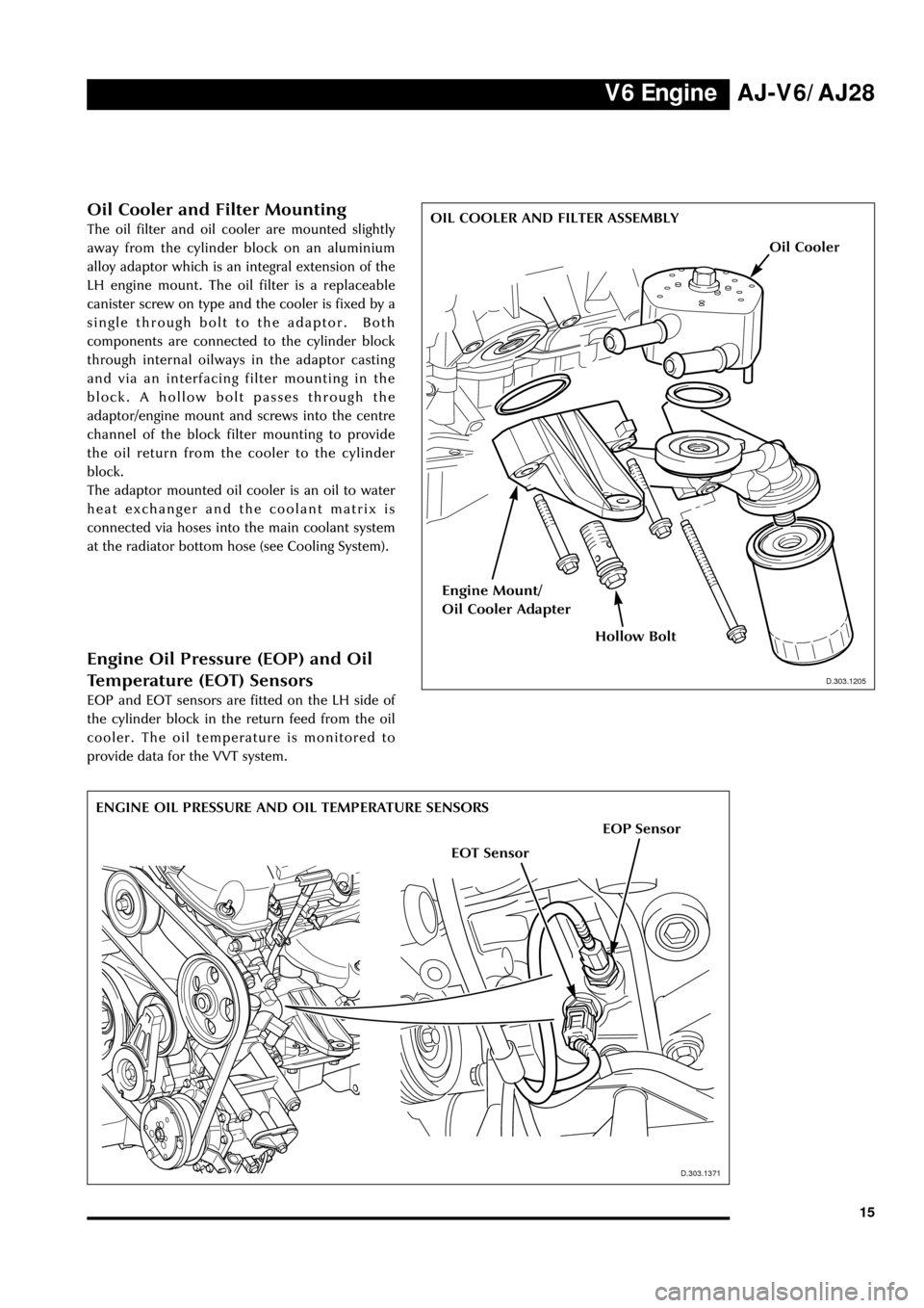
Oil Cooler and Filter Mounting
The oil filter and oil cooler are mounted slightly
away from the cylinder block on an aluminium
alloy adaptor which is an integral extension of the
LH engine mount. The oil filter is a replaceable
canister screw on type and the cooler is fixed by a
single through bolt to the adaptor. Both
components are connected to the cylinder block
through internal oilways in the adaptor casting
and via an interfacing filter mounting in the
block. A hollow bolt passes through the
adaptor/engine mount and screws into the centre
channel of the block filter mounting to provide
the oil return from the cooler to the cylinder
block.
The adaptor mounted oil cooler is an oil to water
heat exchanger and the coolant matrix is
connected via hoses into the main coolant system
at the radiator bottom hose (see Cooling System).
ENGINE OIL PRESSURE AND OIL TEMPERATURE SENSORS
D.303.1205
OIL COOLER AND FILTER ASSEMBLY
EOP Sensor
EOT Sensor
D.303.1205
D.303.1371
Engine Oil Pressure (EOP) and Oil
Temperature (EOT) Sensors
EOP and EOT sensors are fitted on the LH side of
the cylinder block in the return feed from the oil
cooler. The oil temperature is monitored to
provide data for the VVT system.
Oil Cooler
Hollow Bolt
Engine Mount/
Oil Cooler Adapter
Page 21 of 75
V6 Engine AJ-V6/AJ28
16
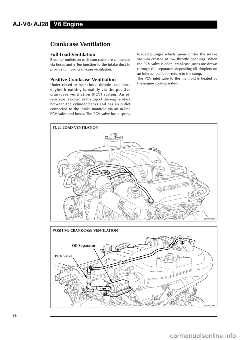
Crankcase Ventilation
Full Load Ventilation
Breather outlets on each cam cover are connected
via hoses and a Tee junction to the intake duct to
provide full load crankcase ventilation.
Positive Crankcase Ventilation
Under closed or near closed throttle conditions,
engine breathing is mainly via the positive
crankcase ventilation (PCV) system. An oil
separator is bolted to the top of the engine block
between the cylinder banks and has an outlet
connected to the intake manifold via an in-line
PCV valve and hoses. The PCV valve has a spring
J.303.1286
FULL LOAD VENTILATION
D.303.1286
loaded plunger which opens under the intake
vacuum created at low throttle openings. When
the PCV valve is open, crankcase gases are drawn
through the separator, depositing oil droplets on
an internal baffle for return to the sump.
The PCV inlet tube to the manifold is heated by
the engine cooling system.
J.303.1290
POSITIVE CRANKCASE VENTILATION
D.303.1290
Oil Separator
PCV valve
Page 22 of 75
V6 EngineAJ-V6/AJ28
17
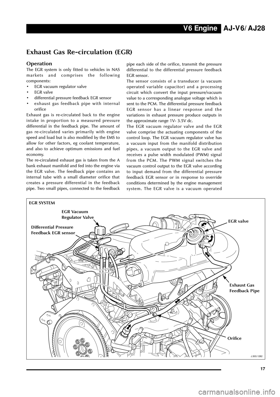
Exhaust Gas Re-circulation (EGR)
Operation
The EGR system is only fitted to vehicles in NAS
markets and comprises the following
components:
¥ EGR vacuum regulator valve
¥ EGR valve
¥ differential pressure feedback EGR sensor
¥ exhaust gas feedback pipe with internal
orifice
Exhaust gas is re-circulated back to the engine
intake in proportion to a measured pressure
differential in the feedback pipe. The amount of
gas re-circulated varies primarily with engine
speed and load but is also modified by the EMS to
allow for other factors, eg coolant temperature,
and also to achieve optimum emissions and fuel
economy.
The re-circulated exhaust gas is taken from the A
bank exhaust manifold and fed into the engine via
the EGR valve. The feedback pipe contains an
internal tube with a small diameter orifice that
creates a pressure differential in the feedback
pipe. Two small pipes, connected to the feedbackpipe each side of the orifice, transmit the pressure
differential to the differential pressure feedback
EGR sensor.
The sensor consists of a transducer (a vacuum
operated variable capacitor) and a processing
circuit which convert the input pressure/vacuum
value to a corresponding analogue voltage which is
sent to the PCM. The differential pressure feedback
EGR sensor has a linear response and the
variations in exhaust pressure produce outputs in
the approximate range 1V- 3.5V dc.
The EGR vacuum regulator valve and the EGR
valve comprise the actuating components of the
control loop. The EGR vacuum regulator valve has
a vacuum input from the manifold distribution
pipes, a vacuum output to the EGR valve and
receives a pulse width modulated (PWM) signal
from the PCM. The PWM signal switches the
vacuum control output to the EGR valve according
to input demand from the differential pressure
feedback EGR sensor or in response to override
conditions determined by the engine management
system. The EGR valve is a vacuum operated
EGR SYSTEM
J.303.1282
Exhaust Gas
Feedback Pipe
Differential Pressure
Feedback EGR sensor
EGR Vacuum
Regulator Valve
EGR valve
Orifice
Page 23 of 75
V6 Engine AJ-V6/AJ28
18diaphragm valve with no electrical connections
which opens the EGR feed pipe to the induction
manifold under the EGR vacuum regulator
control.
Where the EGR system is not fitted, a blanking
plate seals the manifold in place of the EGR valve.
Control Conditions
EGR operates over most of the engine speed/load
range but is disabled by the engine management
system under certain conditions:
¥ during engine cranking
¥ until normal operating temperature is
reached
¥ when the diagnostic system registers a failure
which affects the EGR system (eg a faulty
sensor)
¥ during idling to avoid unstable or erratic
running
¥ during wide open throttle operation
¥ when traction control is operative.
While the main control loop is based on feedback
from the differential pressure feedback EGR
sensor, the EGR rate is also modified by other
engine conditions; coolant, ambient and air
charge temperatures, barometric pressure, VVT
cam position and air charge mass. Note also that
the EGR rate increases gradually after it is enabled
on each drive cycle.
Page 24 of 75
V6 EngineAJ-V6/AJ28
19
Variable Valve Timing (VVT)
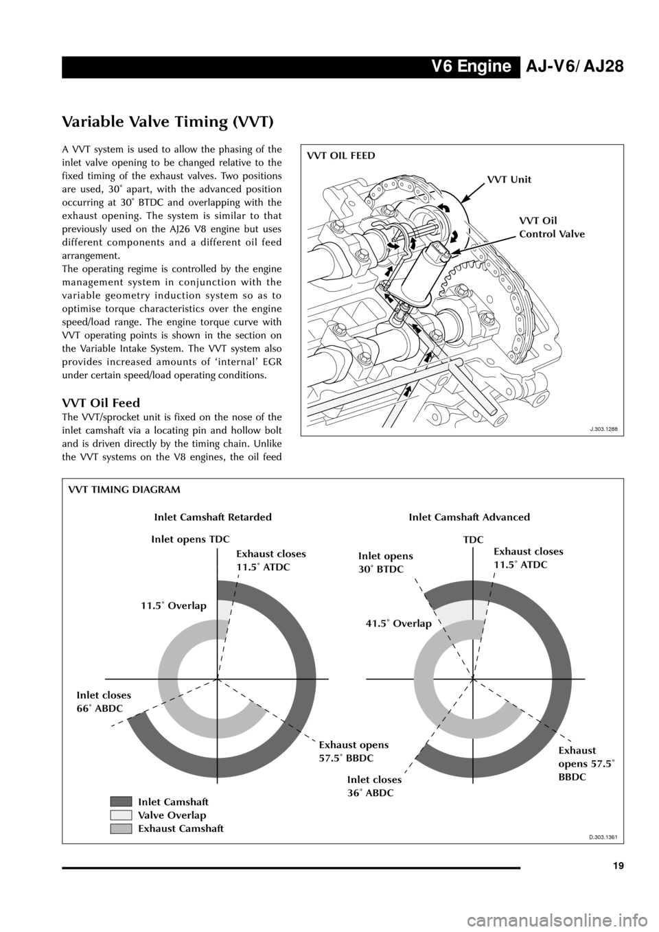
A VVT system is used to allow the phasing of the
inlet valve opening to be changed relative to the
fixed timing of the exhaust valves. Two positions
are used, 30û apart, with the advanced position
occurring at 30û BTDC and overlapping with the
exhaust opening. The system is similar to that
previously used on the AJ26 V8 engine but uses
different components and a different oil feed
arrangement.
The operating regime is controlled by the engine
management system in conjunction with the
variable geometry induction system so as to
optimise torque characteristics over the engine
speed/load range. The engine torque curve with
VVT operating points is shown in the section on
the Variable Intake System. The VVT system also
provides increased amounts of ÔinternalÕ EGR
under certain speed/load operating conditions.
VVT Oil Feed
The VVT/sprocket unit is fixed on the nose of the
inlet camshaft via a locating pin and hollow bolt
and is driven directly by the timing chain. Unlike
the VVT systems on the V8 engines, the oil feed
J.303.1288
VVT OIL FEED
J.303.1288
VVT Unit
VVT Oil
Control Valve
D.303.1361
VVT TIMING DIAGRAM
D.303.1361
Inlet Camshaft RetardedInlet Camshaft Advanced
Inlet opens TDC
Exhaust closes
11.5û ATDCInlet opens
30û BTDCExhaust closes
11.5û ATDC
TDC
Inlet closes
36û ABDC
Exhaust
opens 57.5û
BBDC Inlet closes
66û ABDCExhaust opens
57.5û BBDC41.5û Overlap 11.5û Overlap
Inlet Camshaft
Valve Overlap
Exhaust Camshaft