vvt JAGUAR S TYPE 1999 1.G Powertrain Manual
[x] Cancel search | Manufacturer: JAGUAR, Model Year: 1999, Model line: S TYPE, Model: JAGUAR S TYPE 1999 1.GPages: 75, PDF Size: 3.4 MB
Page 24 of 75
V6 EngineAJ-V6/AJ28
19
Variable Valve Timing (VVT)
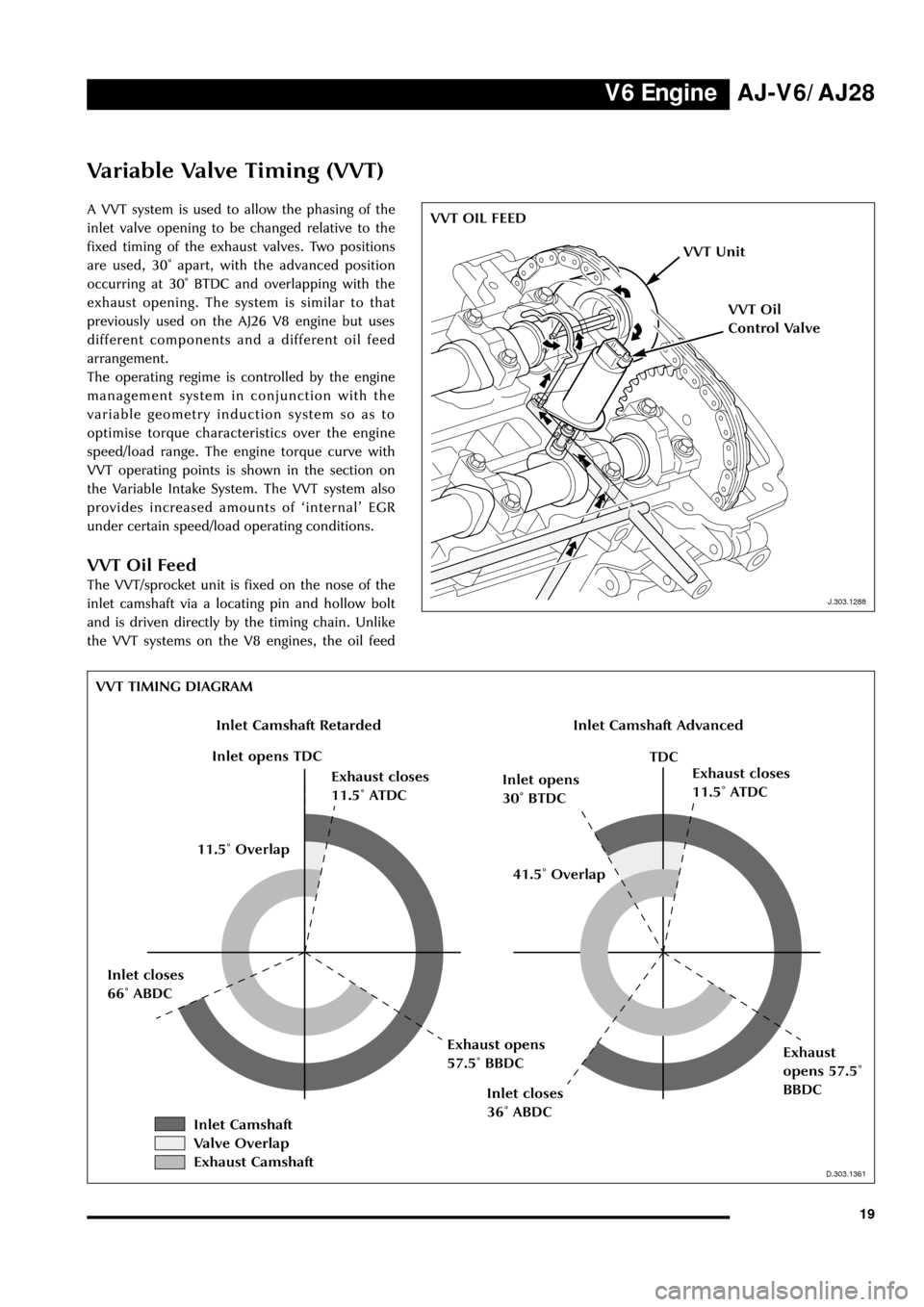
A VVT system is used to allow the phasing of the
inlet valve opening to be changed relative to the
fixed timing of the exhaust valves. Two positions
are used, 30û apart, with the advanced position
occurring at 30û BTDC and overlapping with the
exhaust opening. The system is similar to that
previously used on the AJ26 V8 engine but uses
different components and a different oil feed
arrangement.
The operating regime is controlled by the engine
management system in conjunction with the
variable geometry induction system so as to
optimise torque characteristics over the engine
speed/load range. The engine torque curve with
VVT operating points is shown in the section on
the Variable Intake System. The VVT system also
provides increased amounts of ÔinternalÕ EGR
under certain speed/load operating conditions.
VVT Oil Feed
The VVT/sprocket unit is fixed on the nose of the
inlet camshaft via a locating pin and hollow bolt
and is driven directly by the timing chain. Unlike
the VVT systems on the V8 engines, the oil feed
J.303.1288
VVT OIL FEED
J.303.1288
VVT Unit
VVT Oil
Control Valve
D.303.1361
VVT TIMING DIAGRAM
D.303.1361
Inlet Camshaft RetardedInlet Camshaft Advanced
Inlet opens TDC
Exhaust closes
11.5û ATDCInlet opens
30û BTDCExhaust closes
11.5û ATDC
TDC
Inlet closes
36û ABDC
Exhaust
opens 57.5û
BBDC Inlet closes
66û ABDCExhaust opens
57.5û BBDC41.5û Overlap 11.5û Overlap
Inlet Camshaft
Valve Overlap
Exhaust Camshaft
Page 25 of 75
V6 Engine AJ-V6/AJ28
20to each VVT unit is supplied via fixed oilways in
the cylinder head and not through a separate
bush carrier. This arrangement requires a feed
through the camshaft side of the VVT unit from
the main cylinder head supply. The oil feed is
controlled by the VVT oil control valve, a solenoid
operated shuttle valve, which is bolted directly to
the cylinder head. From the oil control valve, the
flow is via the thrust bearing cap, through
drillings in the camshaft and then through the
hollow fixing bolt which secures the VVT unit.
Drain holes are provided at the rear (camside)
face of the VVT unit for any residual oil which has
seeped past the piston.
Operation
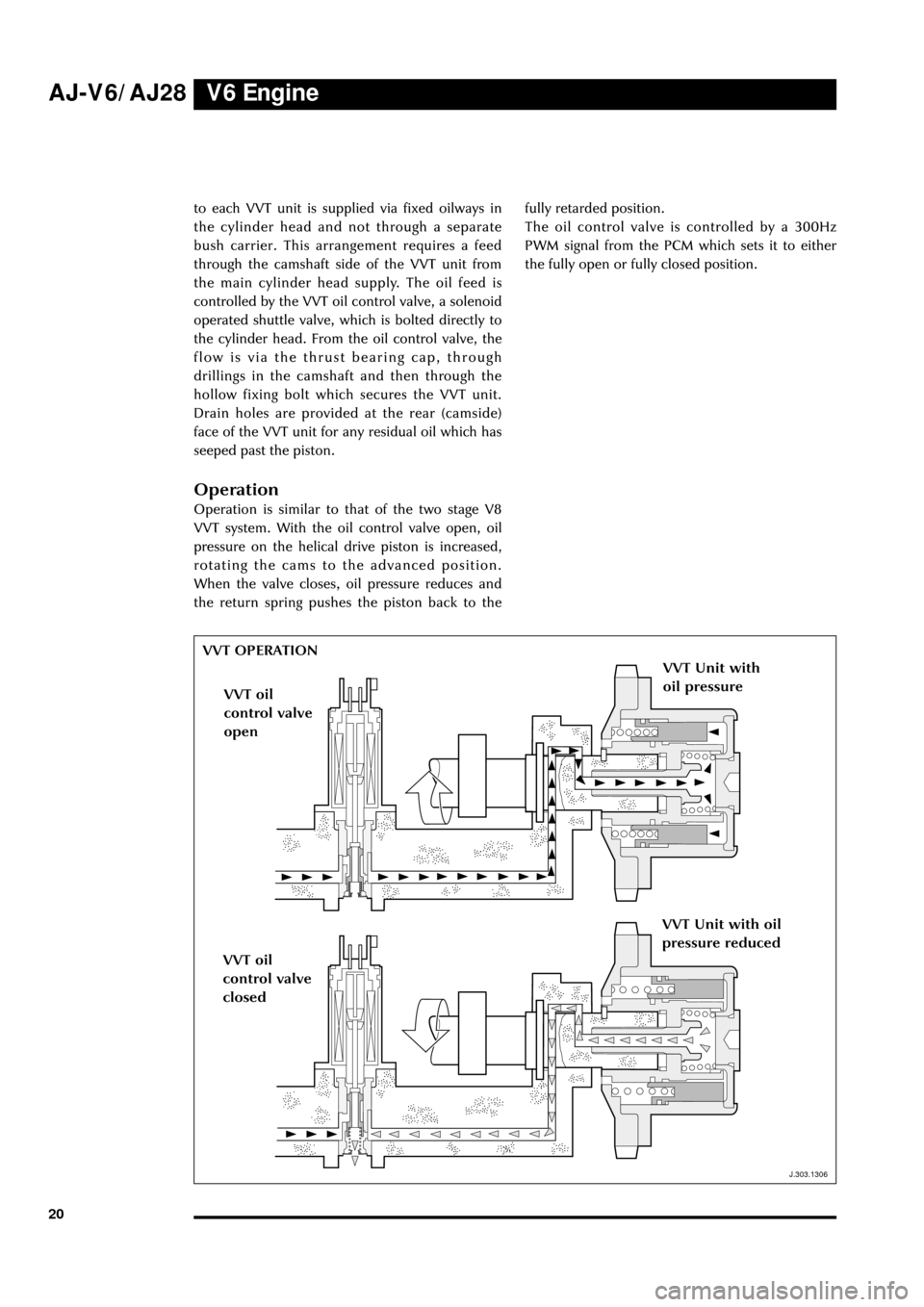
Operation is similar to that of the two stage V8
VVT system. With the oil control valve open, oil
pressure on the helical drive piston is increased,
rotating the cams to the advanced position.
When the valve closes, oil pressure reduces and
the return spring pushes the piston back to thefully retarded position.
The oil control valve is controlled by a 300Hz
PWM signal from the PCM which sets it to either
the fully open or fully closed position.
J.303.1306
VVT OPERATION
VVT Unit with
oil pressure
VVT oil
control valve
open
VVT oil
control valve
closed
VVT Unit with oil
pressure reduced
J.303.1306
Page 29 of 75
V6 Engine AJ-V6/AJ28
24
J.303.1358
TORQUE CHARACTERISTICS
Top inlet manifold tuning valve
Advanced
Closed
325
D.303.1358
Side inlet manifold tuning valve
Open
Closed
Closed
ClosedOpen
Retarded
V. V. T.
175
200
225
250
275
300
125
150
2000700060005000400030001000
Engine Speed (rpm)
Brake Torque (Nm)
chambers via the rear connecting hole,
further increasing the ram effect.via the rear
connecting hole.
System Performance
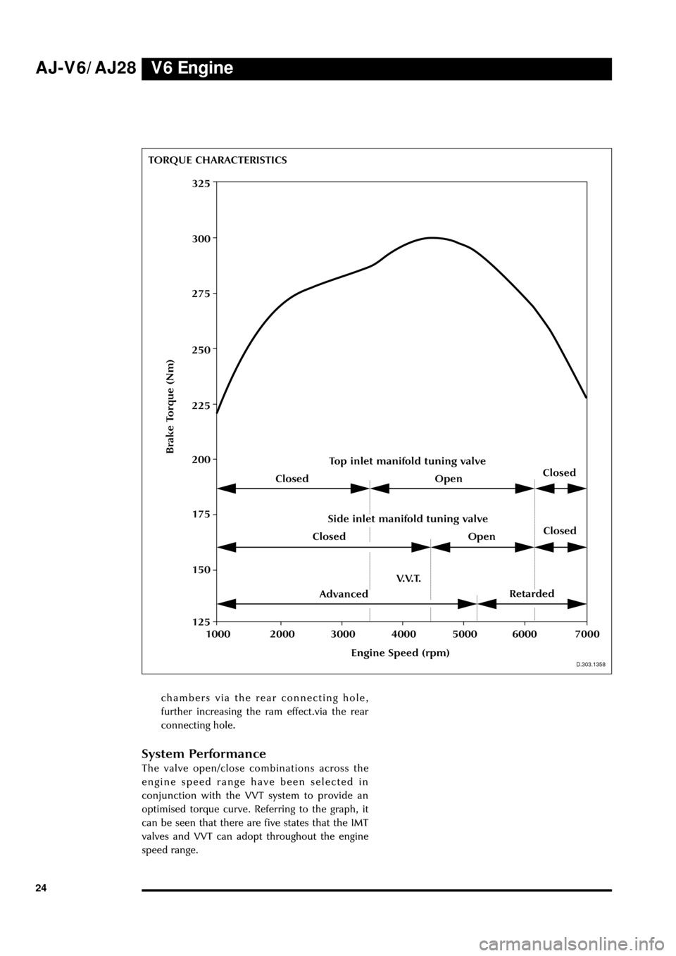
The valve open/close combinations across the
engine speed range have been selected in
conjunction with the VVT system to provide an
optimised torque curve. Referring to the graph, it
can be seen that there are five states that the IMT
valves and VVT can adopt throughout the engine
speed range.
Page 45 of 75
V6 Engine AJ-V6/AJ28
40
Engine Management Sensors
Key to illustration on page 41:
1. Throttle motor
2. TP sensor
3. IAT sensor
4. MAF sensor
5. Top IMT valve
6. Bottom IMT valve
7. EFT sensor
8. IP sensor
9. Fuel injectors
10. Coil-on-plug units
11. VVT shuttle valve
12. CMP sensor
13. CHT sensor
14. KS sensors
15. EOT sensor
16. CKP sensor
17. HO2 sensors
18. HO2 sensors (catalyst monitors)
Cylinder Head Temperature (CHT) Sensor
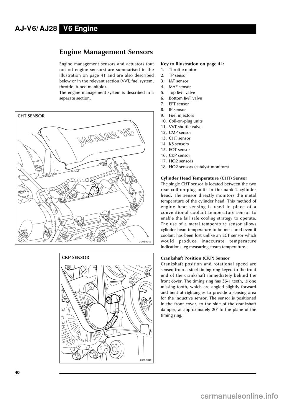
The single CHT sensor is located between the two
rear coil-on-plug units in the bank 2 cylinder
head. The sensor directly monitors the metal
temperature of the cylinder head. This method of
engine heat sensing is used in place of a
conventional coolant temperature sensor to
enable the fail safe cooling strategy to operate.
The use of a metal temperature sensor allows
cylinder head temperature to be measured even if
coolant has been lost unlike an ECT sensor which
would produce inaccurate temperature
indications, eg measuring steam temperature.
Crankshaft Position (CKP) Sensor
Crankshaft position and rotational speed are
sensed from a steel timing ring keyed to the front
end of the crankshaft immediately behind the
front cover. The timing ring has 36-1 teeth, ie one
missing tooth, which are angled slightly forward
and bent at rightangles to provide a sensing area
for the inductive sensor. The sensor is positioned
in the front cover, to the side of the crankshaft
damper, at approximately 20û to the plane of the
timing ring.
D.303.1342
J.303.1343
CHT SENSOR
CKP SENSOR
D.303-1342
J.303-1343
Engine management sensors and actuators (but
not off engine sensors) are summarised in the
illustration on page 41 and are also described
below or in the relevant section (VVT, fuel system,
throttle, tuned manifold).
The engine management system is described in a
separate section.
Page 52 of 75
V8 EngineAJ-V6/AJ28
47
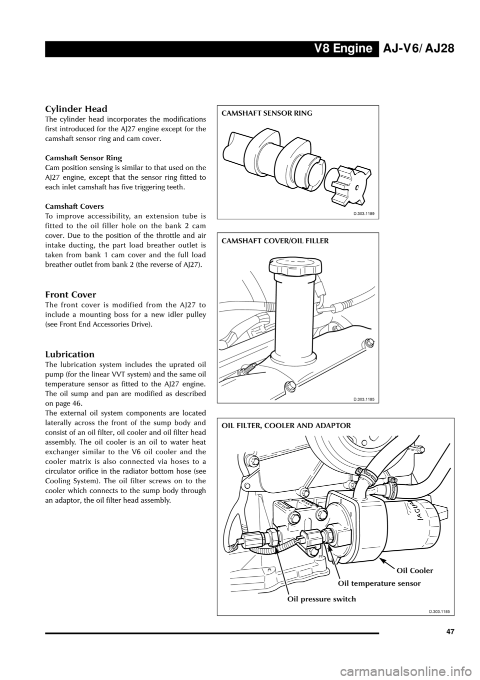
Cylinder Head
The cylinder head incorporates the modifications
first introduced for the AJ27 engine except for the
camshaft sensor ring and cam cover.
Camshaft Sensor Ring
Cam position sensing is similar to that used on the
AJ27 engine, except that the sensor ring fitted to
each inlet camshaft has five triggering teeth.
Camshaft Covers
To improve accessibility, an extension tube is
fitted to the oil filler hole on the bank 2 cam
cover. Due to the position of the throttle and air
intake ducting, the part load breather outlet is
taken from bank 1 cam cover and the full load
breather outlet from bank 2 (the reverse of AJ27).
Front Cover
The front cover is modified from the AJ27 to
include a mounting boss for a new idler pulley
(see Front End Accessories Drive).
Lubrication
The lubrication system includes the uprated oil
pump (for the linear VVT system) and the same oil
temperature sensor as fitted to the AJ27 engine.
The oil sump and pan are modified as described
on page 46.
The external oil system components are located
laterally across the front of the sump body and
consist of an oil filter, oil cooler and oil filter head
assembly. The oil cooler is an oil to water heat
exchanger similar to the V6 oil cooler and the
cooler matrix is also connected via hoses to a
circulator orifice in the radiator bottom hose (see
Cooling System). The oil filter screws on to the
cooler which connects to the sump body through
an adaptor, the oil filter head assembly.
J.303.1189
CAMSHAFT SENSOR RING
D.303.1189
D.303.1185
CAMSHAFT COVER/OIL FILLER
D.303.1185
D.303.1186
OIL FILTER, COOLER AND ADAPTOR
D.303.1185
Oil temperature sensor
Oil pressure switch
Oil Cooler
Page 58 of 75
V8 EngineAJ-V6/AJ28
53
J.303.1359
INDUCTION VACUUM AND AIR SUPPLY CONNECTIONS
J.303.1359
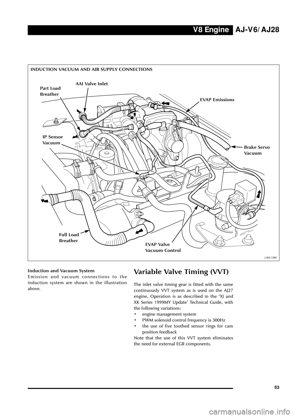
Induction and Vacuum System
Emission and vacuum connections to the
induction system are shown in the illustration
above.Variable Valve Timing (VVT)
The inlet valve timing gear is fitted with the same
continuously VVT system as is used on the AJ27
engine. Operation is as described in the ÔXJ and
XK Series 1999MY UpdateÕ Technical Guide, with
the following variations:
¥ engine management system
¥ PWM solenoid control frequency is 300Hz
¥ the use of five toothed sensor rings for cam
position feedback
Note that the use of this VVT system eliminates
the need for external EGR components.
AAI Valve Inlet
Brake Servo
Vacuum
EVAP Emissions
EVAP Valve
Vacuum Control
Part Load
Breather
IP Sensor
Vacuum
Full Load
Breather
Page 60 of 75
V8 EngineAJ-V6/AJ28
55
J.303.1389
ENGINE MANAGEMENT SCHEMATIC
13
2
45
6
8
157
9
1110
13
16
J.303-1287
9
10
12
14
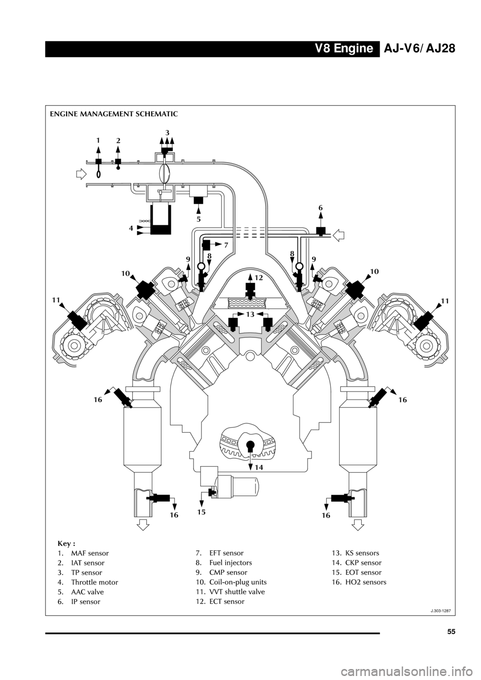
Key :
1. MAF sensor
2. IAT sensor
3. TP sensor
4. Throttle motor
5. AAC valve
6. IP sensor8
11
16
1616
7. EFT sensor
8. Fuel injectors
9. CMP sensor
10. Coil-on-plug units
11. VVT shuttle valve
12. ECT sensor13. KS sensors
14. CKP sensor
15. EOT sensor
16. HO2 sensors