Ect JAGUAR S TYPE 1999 1.G Powertrain Manual
[x] Cancel search | Manufacturer: JAGUAR, Model Year: 1999, Model line: S TYPE, Model: JAGUAR S TYPE 1999 1.GPages: 75, PDF Size: 3.4 MB
Page 5 of 75
Preface AJ-V6/AJ28
This Technical Guide introduces the engines and transmissions for the new S-TYPE sports sedan.
It is intended to give Jaguar Dealer workshop personnel an overview of their construction and operation,
and is for information purposes only.
The contents of this Technical Guide must not be used as a reference source for servicing procedures; all
servicing must be carried out in accordance with the appropriate JTIS disc.
This Technical Guide will not be updated. While every effort is made to ensure accuracy, changes may
occur between going to press and the equipment being introduced to the market. Once the equipment is
in service, details of changes can be obtained from Service Bulletins and revisions to the JTIS disc.
All rights reserved. No part of this publication may be reproduced, stored in a retrieval system or
transmitted, in any form, electronic, mechanical, photocopying, recording or other means without prior
written permission from the Service Division of Jaguar Cars Limited.
Page 6 of 75

ContentsAJ-V6/AJ28
1 G Gl
lo
os
ss
sa
ar
ry
y
Abbreviations 2
I In
nt
tr
ro
od
du
uc
ct
ti
io
on
n
3
V V6
6
E
En
ng
gi
in
ne
e
Introduction 4
Engine Specifications 5
Basic Engine 6
Cylinder Head Assembly 8
Exhaust Manifold 12
Engine Mountings 12
Lubrication System 13
Crankcase Ventilation 15
Exhaust Gas Re-circulation (EGR) 17
Variable Valve Timing (VVT) 19
Air Induction System 21
Throttle Control System 25
Fuel System 29
Ignition System 30
Engine Cooling 31
Front End Accessories Drive 37
Engine Management Sensors 40
V V8
8
E
En
ng
gi
in
ne
e
Introduction 45
Basic Engine 46
Cooling System 49
Air Induction System 51
Variable Valve Timing (VVT) 53
Engine Management Sensors 54
Ignition System 54
Fuel Injection 56
Front End Accessories Drive 59
A Au
ut
to
om
ma
at
ti
ic
c
T
Tr
ra
an
ns
sm
mi
is
ss
si
io
on
n
Introduction 61
Specification 61
Construction and Operation 63
M Ma
an
nu
ua
al
l
T
Tr
ra
an
ns
sm
mi
is
ss
si
io
on
n
Introduction 64
Specification 64
Gear Selector Control 65
Flywheel and Clutch 65
Clutch Pedal Assembly 68
P Po
ow
we
er
rt
tr
ra
ai
in
n
M
Ma
an
na
ag
ge
em
me
en
nt
t
Introduction 69
Powertrain Control Module (PCM) 69
Subject Page
Page 7 of 75

Glossary
2The following abbreviations are used in this document:
A Ab
bb
br
re
ev
vi
ia
at
ti
io
on
nD
De
es
sc
cr
ri
ip
pt
ti
io
on
n
AAC air assisted (injection) control valve
AAI air assisted injection
ABDC after bottom dead centre
A/C air conditioning
AH amp-hour
API American Petroleum Institute
APP accelerator pedal position (sensor)
ATDC after top dead centre
bank 1 A bank
bank 2 B bank
BBDC before bottom dead centre
BTDC before top dead centre
ûC degree Celsius
CHT cylinder head temperature (sensor)
CKP crankshaft position (sensor)
CMP camshaft position (sensor)
ECT engine coolant temperature (sensor)
EFT engine fuel temperature (sensor)
EGR exhaust gas recirculation
EMS engine management system
EOP engine oil pressure (sensor)
EOT engine oil temperature (sensor)
EVAP evaporative emission
ûF degrees Fahrenheit
HO2 heated oxygen (sensor)
Hz Hertz (cycles per second)
IAT intake air temperature (sensor)
IMT intake manifold tuning (valve)
IP injector pressure (sensor)
JTIS Jaguar Technical Information System
KS knock sensor (sensor)
LH lefthand
MAF mass air flow (sensor)
N/A normally aspirated
NAS North American specification
OBDII on-board diagnostics stage 2
PAS power assisted steering
PCM powertrain control module
PCV positive crankcase ventilation
PWM pulse width modulated
RH righthand
RPM revolutions per minute
SAE Society of Automotive Engineers (USA)
SCP standard corporate protocol
TAC throttle actuator control (module)
TP throttle position (sensor)
VVT variable valve timing
W watts
AJ-V6/AJ28
Page 8 of 75

IntroductionAJ-V6/AJ28
3 The new S-TYPE sports sedan has an in-line powertrain and rear wheel drive configuration and is
available with either a 3 Litre V6 or a 4 Litre V8 engine, both normally aspirated. The V6 engine,
designated AJ-V6 is new to the Jaguar range and provides expected Jaguar levels of performance with
smooth power delivery, economy and excellent torque characteristics across the engine speed/load
range. The engine is of a lightweight but rigid design with particular attention paid to minimising noise
and vibration. A major innovation is the use of a variable geometry air intake manifold, which is
controlled, via valves, by the engine management system and produces optimised volumetric efficiency
at all engine speeds. Two stage variable valve timing is also fitted and both systems are optimised
together to achieve the wide torque delivery at all engine speeds.
The V8 engine, designated AJ28, is a developement of the now established engine fitted to the
successfull XK Series sports and XJ Series sedan and incorporates the latest modifications fitted to the
AJ27 variant, in particular the continuously variable valve timing system and air assisted fuel injection.
Both the V6 and V8 engines are fitted with a new, common, electronic throttle which does not require a
mechanical cable. Another new feature, also common to both engines, is the use of a returnless fuel
system to reduce the formation of fuel vapour (evaporative emissions).
A new 5-speed automatic transmission is fitted (with slight differences) to both engines. In certain
markets only, an optional 5-speed manual transmission, with new self-adjusting clutch, is available for
the V6 engine only.
Both engines and the automatic transmission are controlled by a completely new powertrain control
system.
Page 9 of 75
4
Introduction
D.303.1201
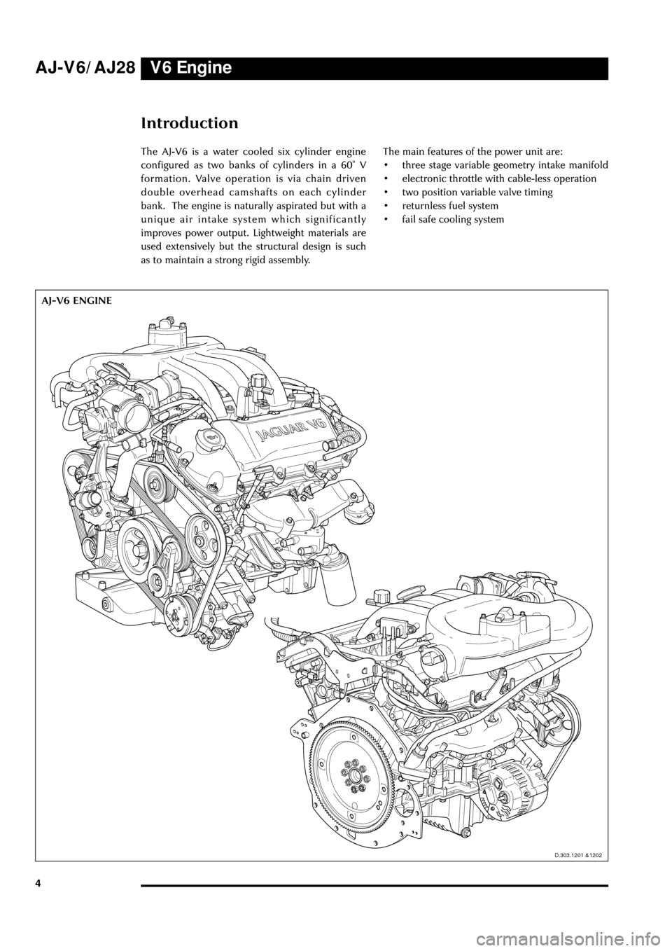
AJ-V6 ENGINEThe AJ-V6 is a water cooled six cylinder engine
configured as two banks of cylinders in a 60û V
formation. Valve operation is via chain driven
double overhead camshafts on each cylinder
bank. The engine is naturally aspirated but with a
unique air intake system which significantly
improves power output. Lightweight materials are
used extensively but the structural design is such
as to maintain a strong rigid assembly.The main features of the power unit are:
¥ three stage variable geometry intake manifold
¥ electronic throttle with cable-less operation
¥ two position variable valve timing
¥ returnless fuel system
¥ fail safe cooling system
V6 Engine
D.303.1202D.303.1201 &1202
AJ-V6/AJ28
Page 11 of 75
V6 Engine
6
Basic Engine
Engine Structure
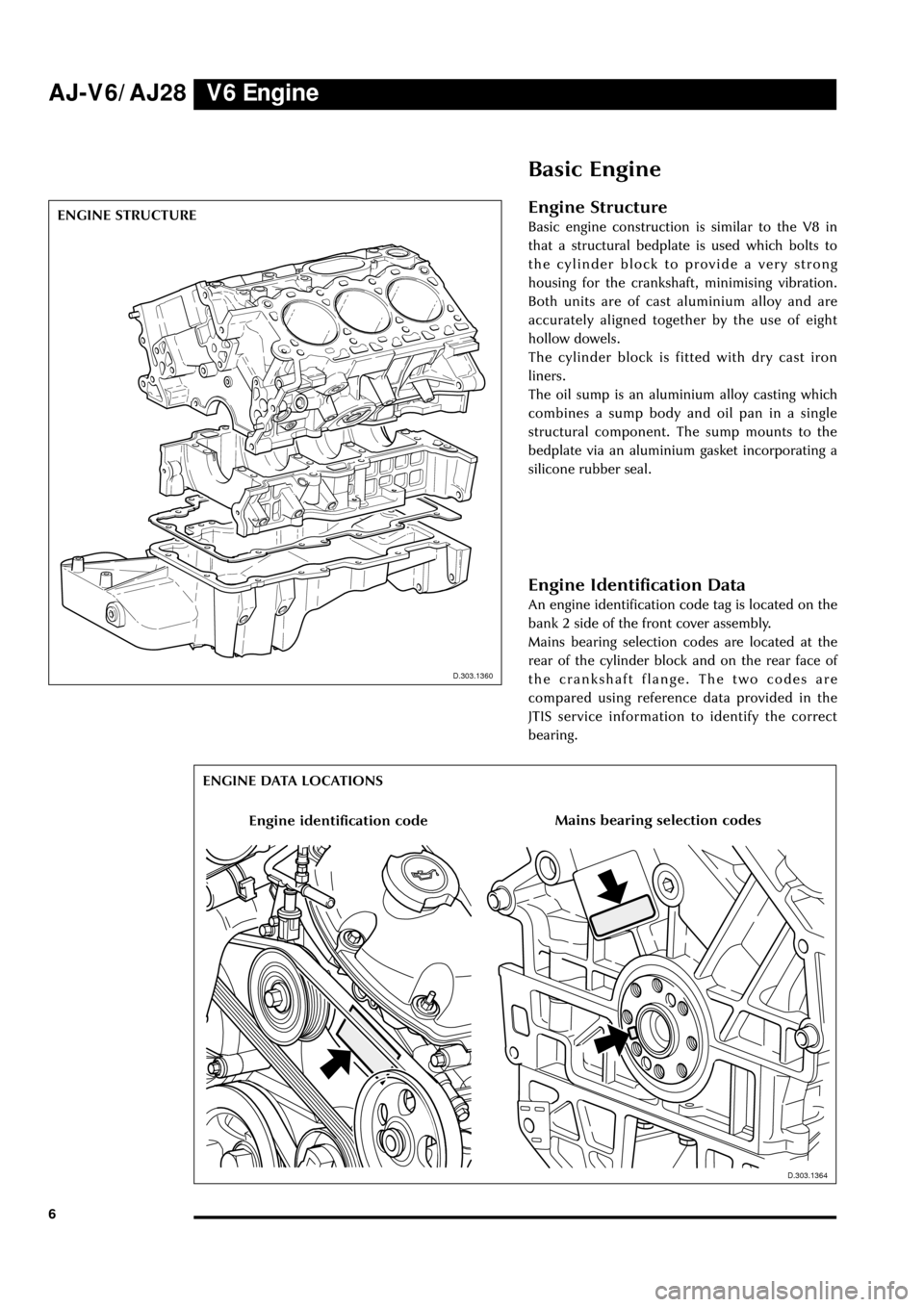
Basic engine construction is similar to the V8 in
that a structural bedplate is used which bolts to
the cylinder block to provide a very strong
housing for the crankshaft, minimising vibration.
Both units are of cast aluminium alloy and are
accurately aligned together by the use of eight
hollow dowels.
The cylinder block is fitted with dry cast iron
liners.
The oil sump is an aluminium alloy casting which
combines a sump body and oil pan in a single
structural component. The sump mounts to the
bedplate via an aluminium gasket incorporating a
silicone rubber seal.
D.303.1360
D.303.1360
ENGINE STRUCTURE
D.303.1364
ENGINE DATA LOCATIONS
Engine Identification Data
An engine identification code tag is located on the
bank 2 side of the front cover assembly.
Mains bearing selection codes are located at the
rear of the cylinder block and on the rear face of
the crankshaft flange. The two codes are
compared using reference data provided in the
JTIS service information to identify the correct
bearing.
Engine identification codeMains bearing selection codes
D.303.1364
AJ-V6/AJ28
Page 12 of 75
D.303.1210
V6 EngineAJ-V6/AJ28
7 CRANKSHAFT
D.303.1210
D.303.1208
CONNECTING ROD AND PISTON
D.303-1208
Crankshaft
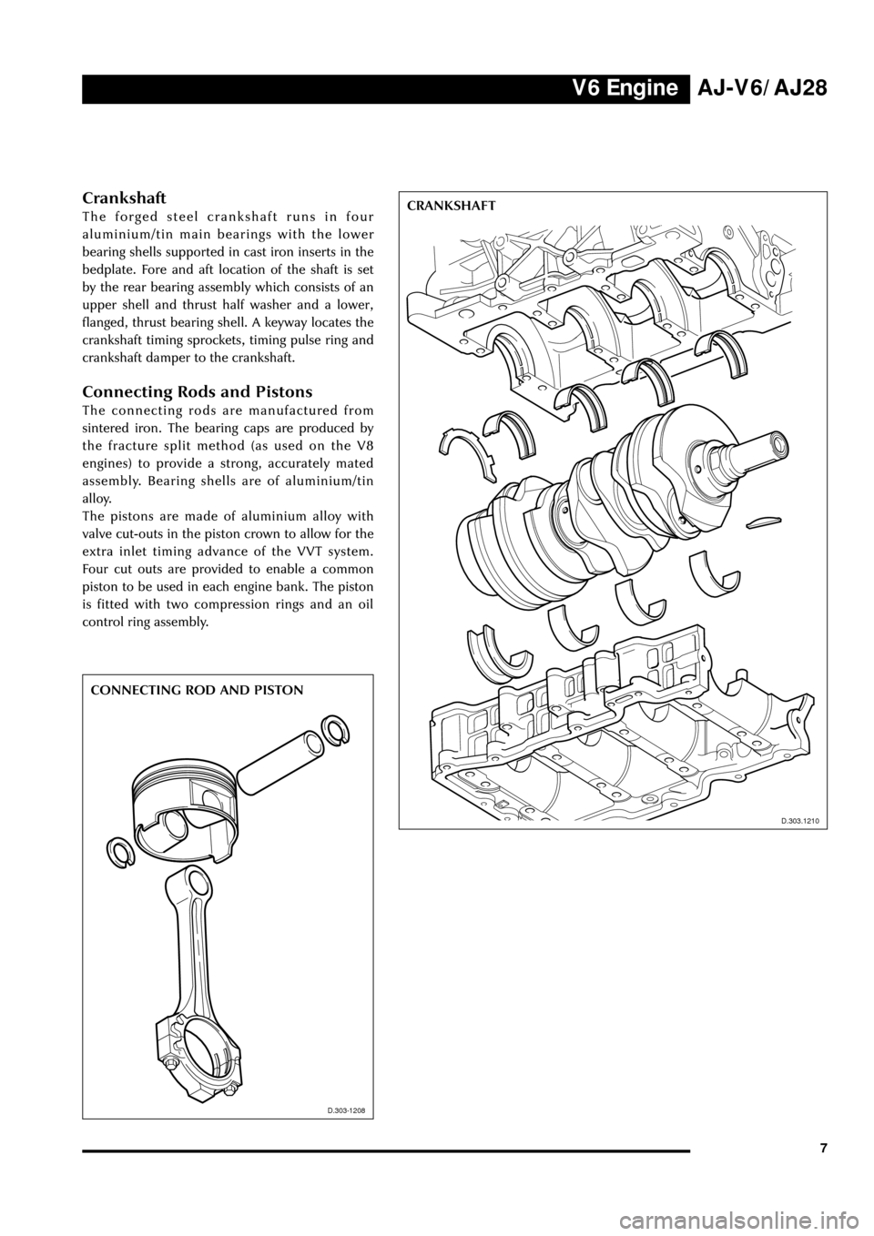
The forged steel crankshaft runs in four
aluminium/tin main bearings with the lower
bearing shells supported in cast iron inserts in the
bedplate. Fore and aft location of the shaft is set
by the rear bearing assembly which consists of an
upper shell and thrust half washer and a lower,
flanged, thrust bearing shell. A keyway locates the
crankshaft timing sprockets, timing pulse ring and
crankshaft damper to the crankshaft.
Connecting Rods and Pistons
The connecting rods are manufactured from
sintered iron. The bearing caps are produced by
the fracture split method (as used on the V8
engines) to provide a strong, accurately mated
assembly. Bearing shells are of aluminium/tin
alloy.
The pistons are made of aluminium alloy with
valve cut-outs in the piston crown to allow for the
extra inlet timing advance of the VVT system.
Four cut outs are provided to enable a common
piston to be used in each engine bank. The piston
is fitted with two compression rings and an oil
control ring assembly.
Page 14 of 75
V6 EngineAJ-V6/AJ28
9
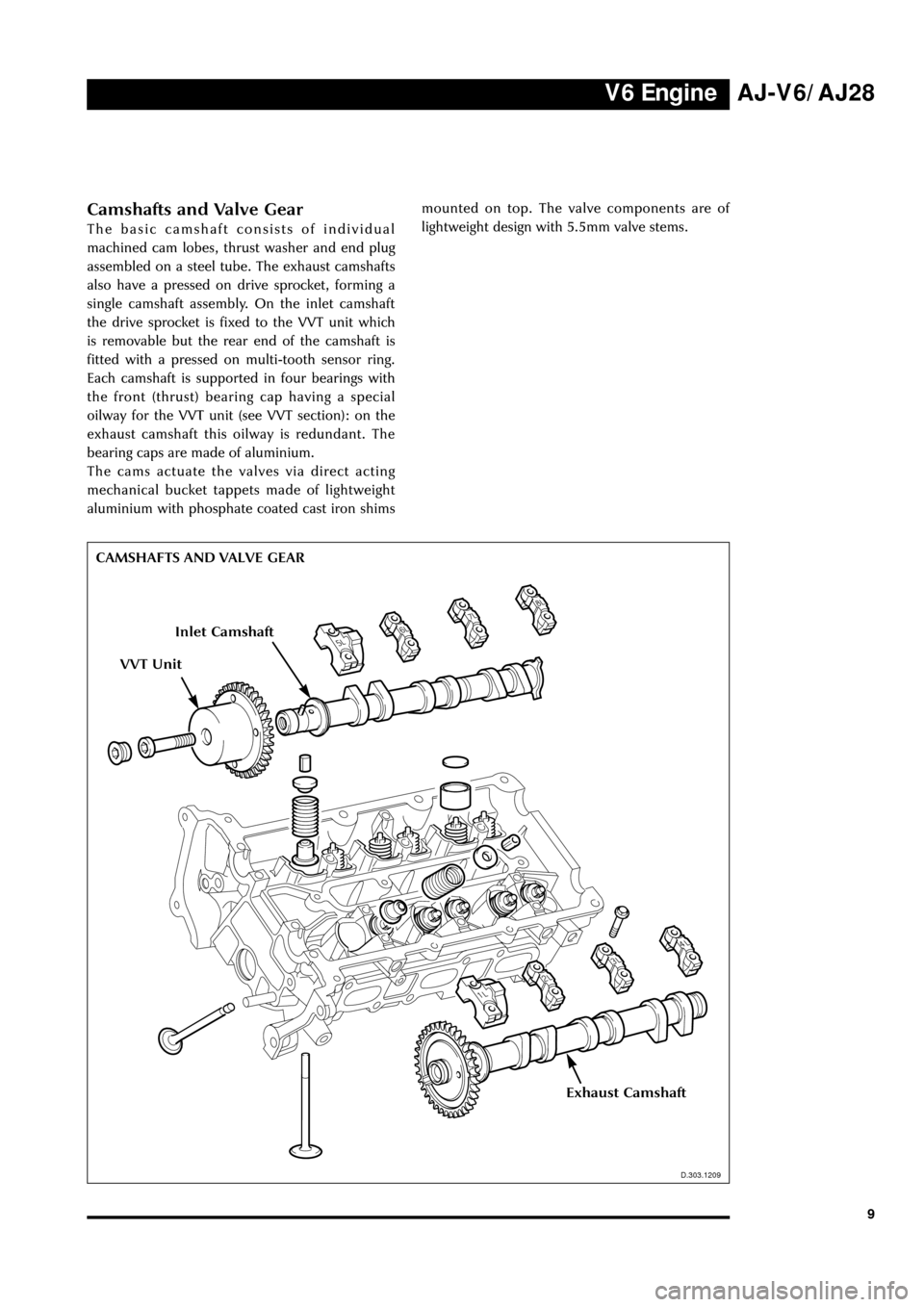
Camshafts and Valve Gear
The basic camshaft consists of individual
machined cam lobes, thrust washer and end plug
assembled on a steel tube. The exhaust camshafts
also have a pressed on drive sprocket, forming a
single camshaft assembly. On the inlet camshaft
the drive sprocket is fixed to the VVT unit which
is removable but the rear end of the camshaft is
fitted with a pressed on multi-tooth sensor ring.
Each camshaft is supported in four bearings with
the front (thrust) bearing cap having a special
oilway for the VVT unit (see VVT section): on the
exhaust camshaft this oilway is redundant. The
bearing caps are made of aluminium.
The cams actuate the valves via direct acting
mechanical bucket tappets made of lightweight
aluminium with phosphate coated cast iron shims
D.303.1209
CAMSHAFTS AND VALVE GEAR
D.303.1209
mounted on top. The valve components are of
lightweight design with 5.5mm valve stems.
VVT Unit
Inlet Camshaft
Exhaust Camshaft
Page 18 of 75
V6 EngineAJ-V6/AJ28
13
Oil Distribution
(see illustration on page 14)
Oil distribution within the block and cylinder
heads is similar to that of the V8 engine, the main
differences being in the filter and cooler
arrangement and the method of supplying the
VVT system.
Oil is drawn from the sump through the strainer
by the crankshaft driven pump, passes through
the externally mounted filter and oil cooler and
returns to the block. Distribution is via the main
gallery and crankshaft oilways to the lower
crankcase components and via branch feeds to
the chain tensioners and then cylinder head
components. Extra oilways in the cylinder heads
provide a built-in feed for the VVT components
(see VVT section).
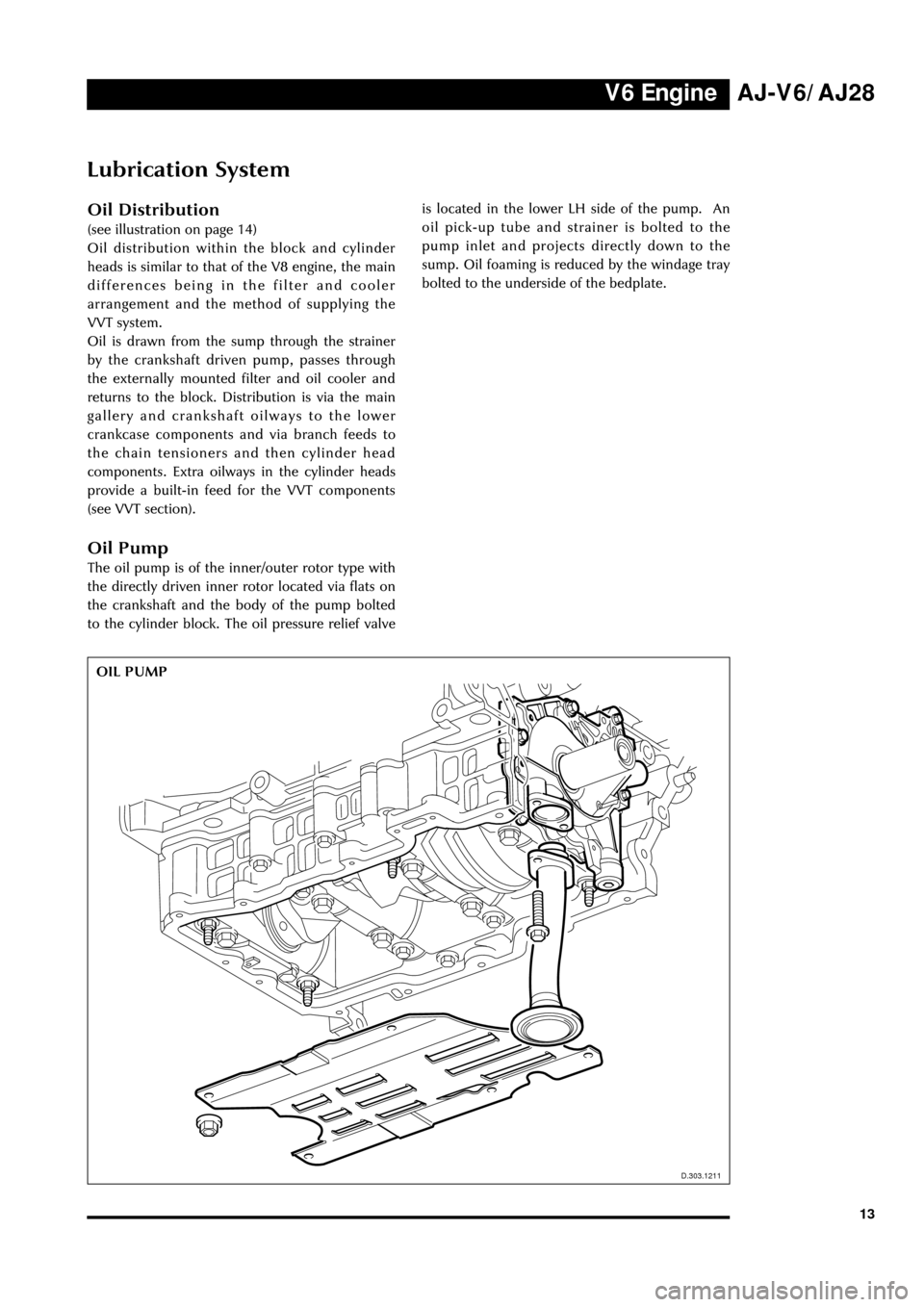
Oil Pump
The oil pump is of the inner/outer rotor type with
the directly driven inner rotor located via flats on
the crankshaft and the body of the pump bolted
to the cylinder block. The oil pressure relief valveis located in the lower LH side of the pump. An
oil pick-up tube and strainer is bolted to the
pump inlet and projects directly down to the
sump. Oil foaming is reduced by the windage tray
bolted to the underside of the bedplate.
D.303.1211
Lubrication System
OIL PUMP
D.303.1211
Page 20 of 75
V6 EngineAJ-V6/AJ28
15
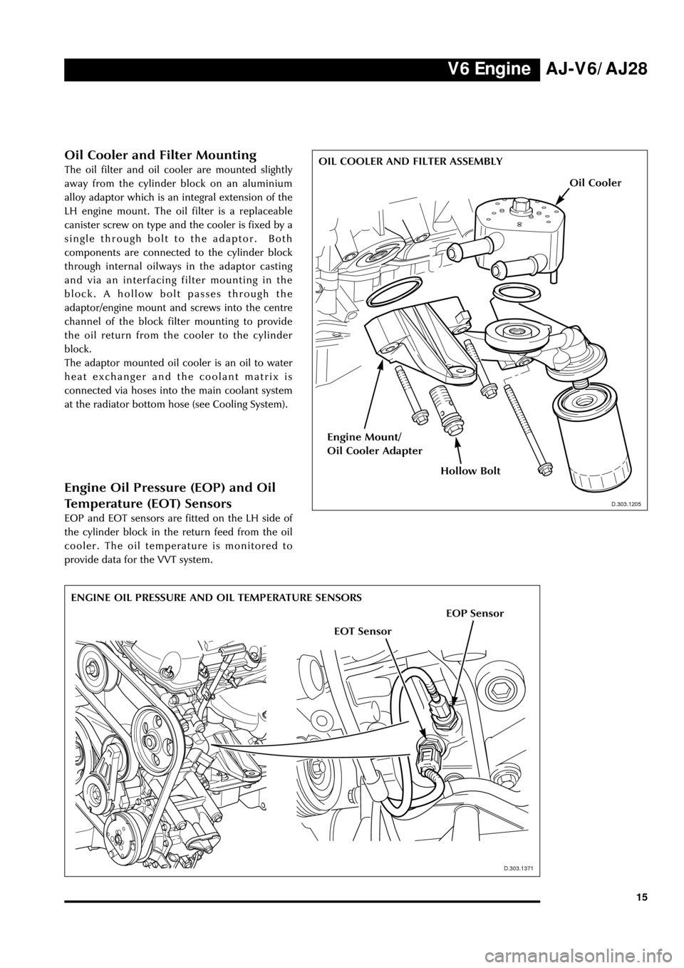
Oil Cooler and Filter Mounting
The oil filter and oil cooler are mounted slightly
away from the cylinder block on an aluminium
alloy adaptor which is an integral extension of the
LH engine mount. The oil filter is a replaceable
canister screw on type and the cooler is fixed by a
single through bolt to the adaptor. Both
components are connected to the cylinder block
through internal oilways in the adaptor casting
and via an interfacing filter mounting in the
block. A hollow bolt passes through the
adaptor/engine mount and screws into the centre
channel of the block filter mounting to provide
the oil return from the cooler to the cylinder
block.
The adaptor mounted oil cooler is an oil to water
heat exchanger and the coolant matrix is
connected via hoses into the main coolant system
at the radiator bottom hose (see Cooling System).
ENGINE OIL PRESSURE AND OIL TEMPERATURE SENSORS
D.303.1205
OIL COOLER AND FILTER ASSEMBLY
EOP Sensor
EOT Sensor
D.303.1205
D.303.1371
Engine Oil Pressure (EOP) and Oil
Temperature (EOT) Sensors
EOP and EOT sensors are fitted on the LH side of
the cylinder block in the return feed from the oil
cooler. The oil temperature is monitored to
provide data for the VVT system.
Oil Cooler
Hollow Bolt
Engine Mount/
Oil Cooler Adapter