air condition JAGUAR S TYPE 1999 1.G Powertrain Manual
[x] Cancel search | Manufacturer: JAGUAR, Model Year: 1999, Model line: S TYPE, Model: JAGUAR S TYPE 1999 1.GPages: 75, PDF Size: 3.4 MB
Page 7 of 75

Glossary
2The following abbreviations are used in this document:
A Ab
bb
br
re
ev
vi
ia
at
ti
io
on
nD
De
es
sc
cr
ri
ip
pt
ti
io
on
n
AAC air assisted (injection) control valve
AAI air assisted injection
ABDC after bottom dead centre
A/C air conditioning
AH amp-hour
API American Petroleum Institute
APP accelerator pedal position (sensor)
ATDC after top dead centre
bank 1 A bank
bank 2 B bank
BBDC before bottom dead centre
BTDC before top dead centre
ûC degree Celsius
CHT cylinder head temperature (sensor)
CKP crankshaft position (sensor)
CMP camshaft position (sensor)
ECT engine coolant temperature (sensor)
EFT engine fuel temperature (sensor)
EGR exhaust gas recirculation
EMS engine management system
EOP engine oil pressure (sensor)
EOT engine oil temperature (sensor)
EVAP evaporative emission
ûF degrees Fahrenheit
HO2 heated oxygen (sensor)
Hz Hertz (cycles per second)
IAT intake air temperature (sensor)
IMT intake manifold tuning (valve)
IP injector pressure (sensor)
JTIS Jaguar Technical Information System
KS knock sensor (sensor)
LH lefthand
MAF mass air flow (sensor)
N/A normally aspirated
NAS North American specification
OBDII on-board diagnostics stage 2
PAS power assisted steering
PCM powertrain control module
PCV positive crankcase ventilation
PWM pulse width modulated
RH righthand
RPM revolutions per minute
SAE Society of Automotive Engineers (USA)
SCP standard corporate protocol
TAC throttle actuator control (module)
TP throttle position (sensor)
VVT variable valve timing
W watts
AJ-V6/AJ28
Page 23 of 75

V6 Engine AJ-V6/AJ28
18diaphragm valve with no electrical connections
which opens the EGR feed pipe to the induction
manifold under the EGR vacuum regulator
control.
Where the EGR system is not fitted, a blanking
plate seals the manifold in place of the EGR valve.
Control Conditions
EGR operates over most of the engine speed/load
range but is disabled by the engine management
system under certain conditions:
¥ during engine cranking
¥ until normal operating temperature is
reached
¥ when the diagnostic system registers a failure
which affects the EGR system (eg a faulty
sensor)
¥ during idling to avoid unstable or erratic
running
¥ during wide open throttle operation
¥ when traction control is operative.
While the main control loop is based on feedback
from the differential pressure feedback EGR
sensor, the EGR rate is also modified by other
engine conditions; coolant, ambient and air
charge temperatures, barometric pressure, VVT
cam position and air charge mass. Note also that
the EGR rate increases gradually after it is enabled
on each drive cycle.
Page 44 of 75

V6 EngineAJ-V6/AJ28
39
D.303.1351D.303.1352
PAS PUMPA/C COMPRESSOR
D.303.1352
D.303.1369
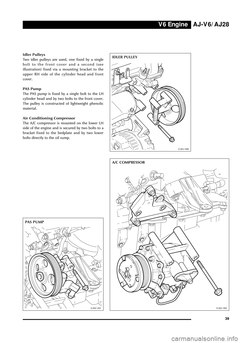
Idler Pulleys
Two idler pulleys are used, one fixed by a single
bolt to the front cover and a second (see
illustration) fixed via a mounting bracket to the
upper RH side of the cylinder head and front
cover.
PAS Pump
The PAS pump is fixed by a single bolt to the LH
cylinder head and by two bolts to the front cover.
The pulley is constructed of lightweight phenolic
material.
Air Conditioning Compressor
The A/C compressor is mounted on the lower LH
side of the engine and is secured by two bolts to a
bracket fixed to the bedplate and by two lower
bolts directly to the oil sump.IDLER PULLEY
D.303.1351
D.303.1369
Page 50 of 75

V8 EngineAJ-V6/AJ28
45
Introduction
The AJ28 engine is a variant of the 4.0L 90û V8 units fitted to the XJ and XK range of vehicles. The AJ28
shares some of the changes incorporated in the current AJ27 engine: both engines are derived from the
original AJ26 unit. A number of features are unique to the AJ28 or are shared with the AJ-V6 engine also
described in this publication.
Features of the AJ28 engine are:
¥ Continuously variable inlet valve timing over a 48û
+
-2û crank angle: as fitted to the AJ27 engine
¥ Full authority cable-less electronic throttle control: as fitted to the AJ-V6 engine
¥ Air assisted fuel injection: similar to system used on the AJ27 engine
¥ Unique induction manifold with centrally mounted throttle body
¥ Returnless fuel system: similar to AJ-V6 engine
¥ Twin wall exhaust manifold
¥ Engine management system as used on the AJ-V6
¥ New sensors
¥ Modified sump and oil cooler
¥ Modified front end ancillary drive and components
Engine Specification
Maximum power DIN - 209 kW (281 BHP) at 6100 RPM
EEC - 203 kW (276 PS) at 6100 RPM
Maximum torque DIN - 390 Nm (287 lbft) at 4300 RPM
EEC - 278 Nm (279 lbft) at 4300 RPM
Oil Specification
All markets except the USA and Canada
Engine oil for all markets except the USA and
Canada must be to API specification SJ/ACEA A1
or A3.
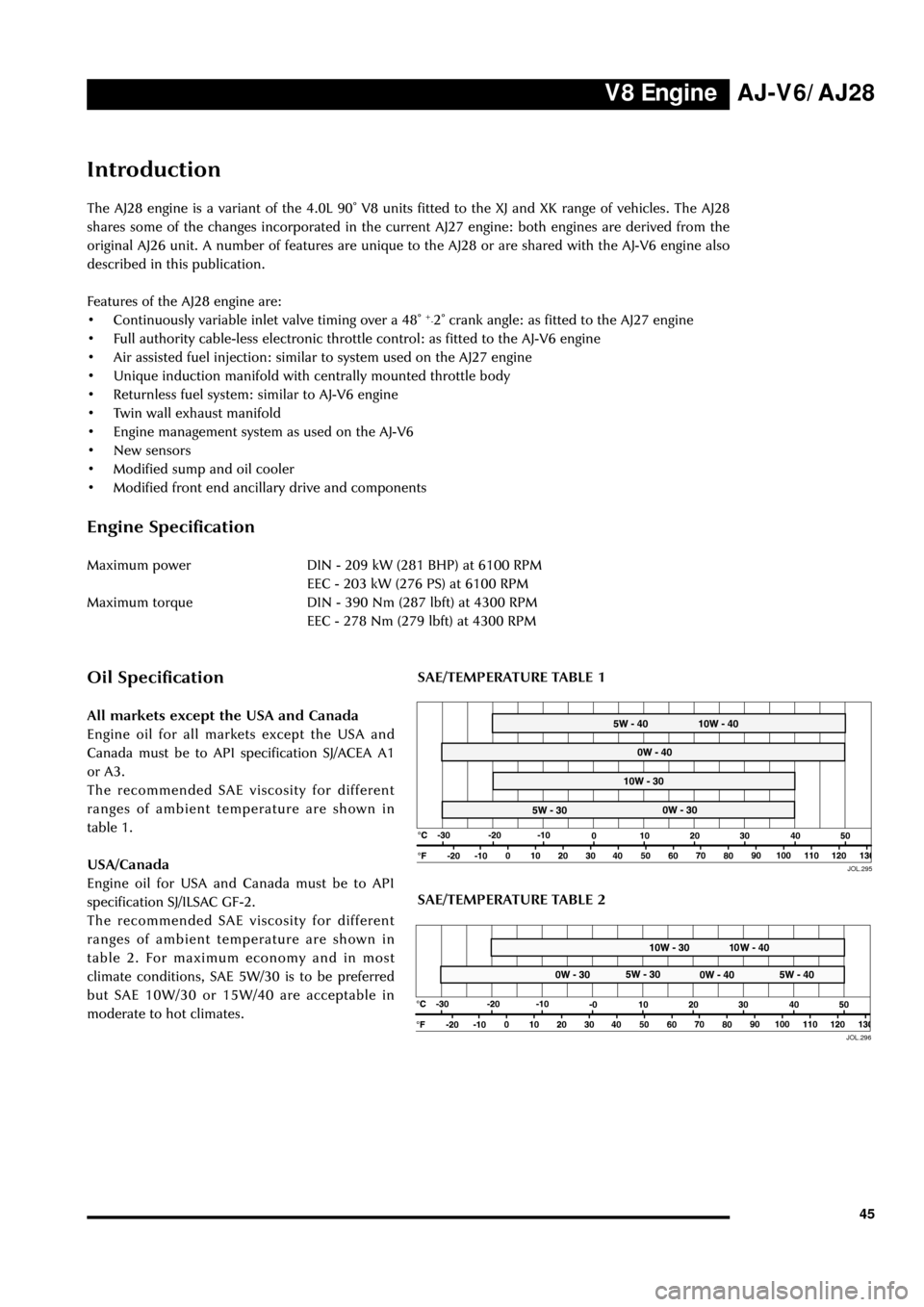
The recommended SAE viscosity for different
ranges of ambient temperature are shown in
table 1.
USA/Canada
Engine oil for USA and Canada must be to API
specification SJ/ILSAC GF-2.
The recommended SAE viscosity for different
ranges of ambient temperature are shown in
table 2. For maximum economy and in most
climate conditions, SAE 5W/30 is to be preferred
but SAE 10W/30 or 15W/40 are acceptable in
moderate to hot climates.
JOL.29550
50JOL.296
SAE/TEMPERATURE TABLE 2
SAE/TEMPERATURE TABLE 1
Page 68 of 75

Automatic TransmissionAJ-V6/AJ28
63 controlled solenoid are mounted on an
integral, replaceable, control module
¥ three speed sensors mounted on the external
casing: turbine speed sensor, intermediate
speed sensor and output speed sensor
¥ an oil temperature sensor is fitted inside the
transmission.
The gear select lever is connected via a Bowden
cable to an operating lever on the left side of the
transmission casing. A digital rotary switch, the
transmission range switch, fits over the shaft of
the operating lever and is fixed by two bolts to
the transmission casing. Selection of a particular
drive function generates a 4 bit binary coded
signal which is transmitted directly to the PCM
over a four wire parallel interface. As on the XK
and XJ Series, lateral movement of the gear select
lever across the gate, D to 4 or 4 to D, operates a
switch which indicates the selected function to
the PCM (the Bowden cable is not actuated
laterally).
The PCM directly controls the transmission
actuators as a response to driver demand, engine
requirements and according to the selected shift
mode. Gear selection is controlled by commands
to the four shift solenoids. If, during gear
selection, the relative speeds monitored by the
speed sensors are not as expected, the PCM
varies the analogue signal to the variable force
solenoids to increase/decrease the clutch pressure
(closed loop control). Increased engagement times
due to ageing are also controlled by adaptive shiftpressure.
Apart from the sports mode and traction mode
selected by the driver, there are pre-programmed
modes selected by the PCM in response to sensed
driving conditions :
¥ increased load such as gradients and trailer
towing
¥ cruise control
¥ hot mode: strategies including clutch lock up
are applied to reduce heat.
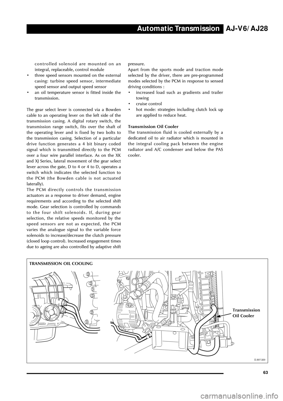
Transmission Oil Cooler
The transmission fluid is cooled externally by a
dedicated oil to air radiator which is mounted in
the integral cooling pack between the engine
radiator and A/C condenser and below the PAS
cooler.
D.307.320
TRANSMISSION OIL COOLING
Transmission
Oil Cooler
D.307.320