key JAGUAR S TYPE 1999 1.G Powertrain Manual
[x] Cancel search | Manufacturer: JAGUAR, Model Year: 1999, Model line: S TYPE, Model: JAGUAR S TYPE 1999 1.GPages: 75, PDF Size: 3.4 MB
Page 12 of 75

D.303.1210
V6 EngineAJ-V6/AJ28
7 CRANKSHAFT
D.303.1210
D.303.1208
CONNECTING ROD AND PISTON
D.303-1208
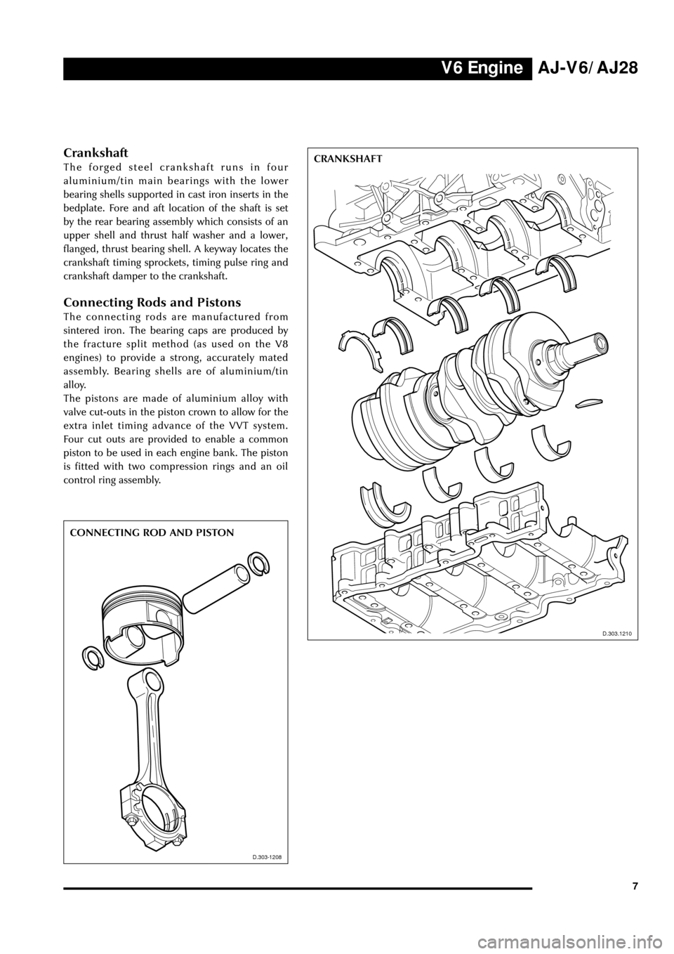
Crankshaft
The forged steel crankshaft runs in four
aluminium/tin main bearings with the lower
bearing shells supported in cast iron inserts in the
bedplate. Fore and aft location of the shaft is set
by the rear bearing assembly which consists of an
upper shell and thrust half washer and a lower,
flanged, thrust bearing shell. A keyway locates the
crankshaft timing sprockets, timing pulse ring and
crankshaft damper to the crankshaft.
Connecting Rods and Pistons
The connecting rods are manufactured from
sintered iron. The bearing caps are produced by
the fracture split method (as used on the V8
engines) to provide a strong, accurately mated
assembly. Bearing shells are of aluminium/tin
alloy.
The pistons are made of aluminium alloy with
valve cut-outs in the piston crown to allow for the
extra inlet timing advance of the VVT system.
Four cut outs are provided to enable a common
piston to be used in each engine bank. The piston
is fitted with two compression rings and an oil
control ring assembly.
Page 15 of 75

V6 Engine
10
D.303.1204
CAMSHAFT DRIVE
D.303.1204
AJ-V6/AJ28
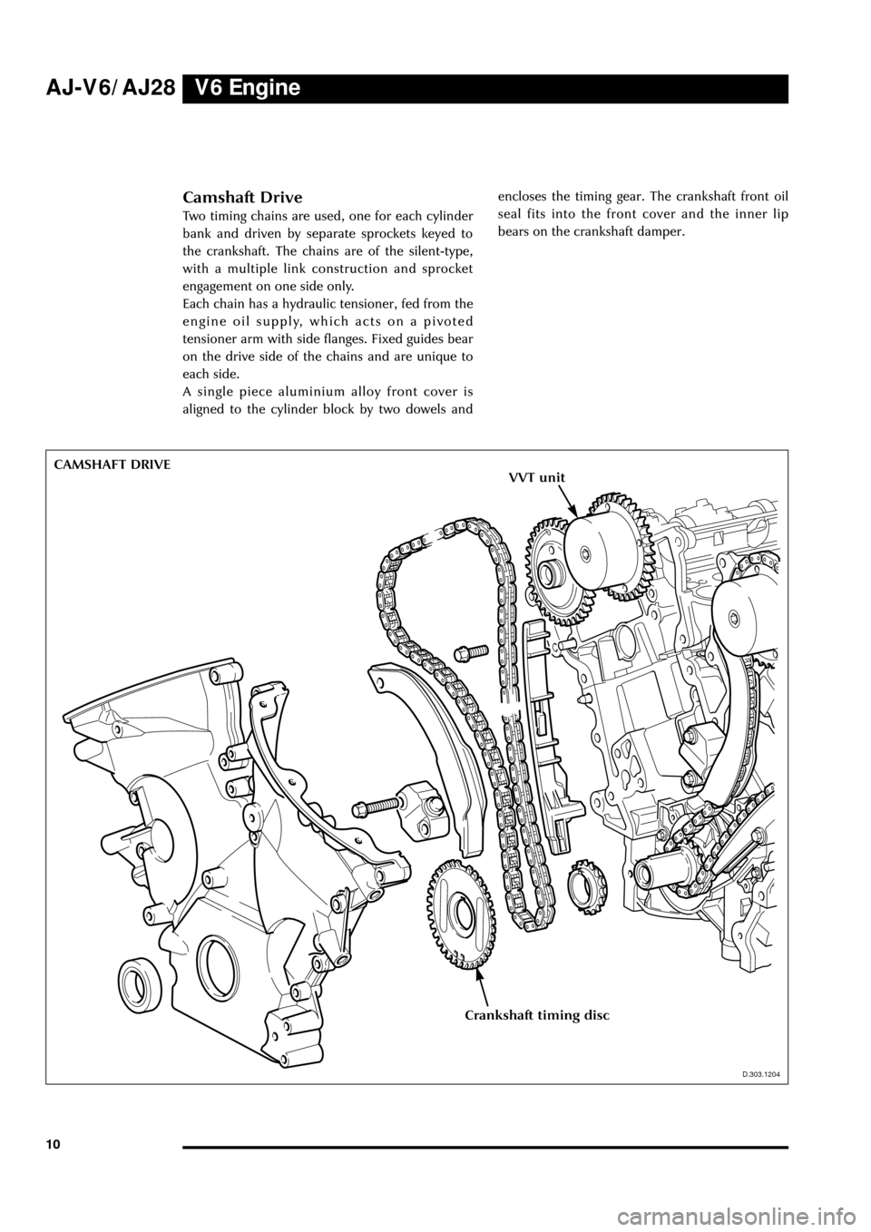
Camshaft Drive
Two timing chains are used, one for each cylinder
bank and driven by separate sprockets keyed to
the crankshaft. The chains are of the silent-type,
with a multiple link construction and sprocket
engagement on one side only.
Each chain has a hydraulic tensioner, fed from the
engine oil supply, which acts on a pivoted
tensioner arm with side flanges. Fixed guides bear
on the drive side of the chains and are unique to
each side.
A single piece aluminium alloy front cover is
aligned to the cylinder block by two dowels andencloses the timing gear. The crankshaft front oil
seal fits into the front cover and the inner lip
bears on the crankshaft damper.
Crankshaft timing disc
VVT unit
Page 45 of 75

V6 Engine AJ-V6/AJ28
40
Engine Management Sensors
Key to illustration on page 41:
1. Throttle motor
2. TP sensor
3. IAT sensor
4. MAF sensor
5. Top IMT valve
6. Bottom IMT valve
7. EFT sensor
8. IP sensor
9. Fuel injectors
10. Coil-on-plug units
11. VVT shuttle valve
12. CMP sensor
13. CHT sensor
14. KS sensors
15. EOT sensor
16. CKP sensor
17. HO2 sensors
18. HO2 sensors (catalyst monitors)
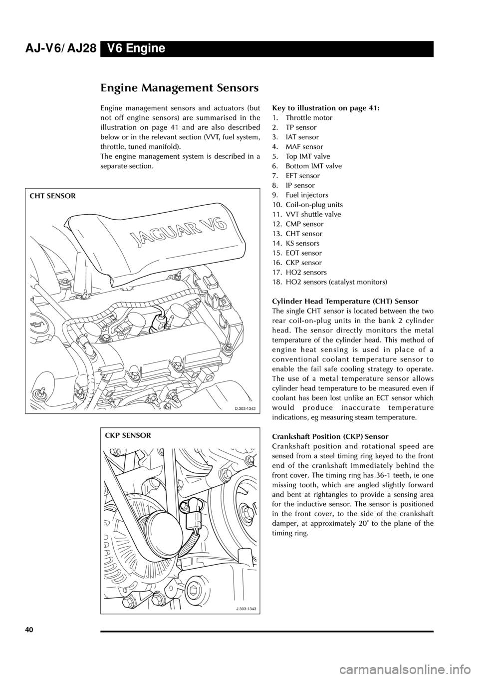
Cylinder Head Temperature (CHT) Sensor
The single CHT sensor is located between the two
rear coil-on-plug units in the bank 2 cylinder
head. The sensor directly monitors the metal
temperature of the cylinder head. This method of
engine heat sensing is used in place of a
conventional coolant temperature sensor to
enable the fail safe cooling strategy to operate.
The use of a metal temperature sensor allows
cylinder head temperature to be measured even if
coolant has been lost unlike an ECT sensor which
would produce inaccurate temperature
indications, eg measuring steam temperature.
Crankshaft Position (CKP) Sensor
Crankshaft position and rotational speed are
sensed from a steel timing ring keyed to the front
end of the crankshaft immediately behind the
front cover. The timing ring has 36-1 teeth, ie one
missing tooth, which are angled slightly forward
and bent at rightangles to provide a sensing area
for the inductive sensor. The sensor is positioned
in the front cover, to the side of the crankshaft
damper, at approximately 20û to the plane of the
timing ring.
D.303.1342
J.303.1343
CHT SENSOR
CKP SENSOR
D.303-1342
J.303-1343
Engine management sensors and actuators (but
not off engine sensors) are summarised in the
illustration on page 41 and are also described
below or in the relevant section (VVT, fuel system,
throttle, tuned manifold).
The engine management system is described in a
separate section.
Page 60 of 75

V8 EngineAJ-V6/AJ28
55
J.303.1389
ENGINE MANAGEMENT SCHEMATIC
13
2
45
6
8
157
9
1110
13
16
J.303-1287
9
10
12
14
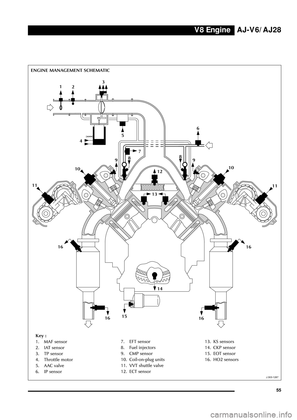
Key :
1. MAF sensor
2. IAT sensor
3. TP sensor
4. Throttle motor
5. AAC valve
6. IP sensor8
11
16
1616
7. EFT sensor
8. Fuel injectors
9. CMP sensor
10. Coil-on-plug units
11. VVT shuttle valve
12. ECT sensor13. KS sensors
14. CKP sensor
15. EOT sensor
16. HO2 sensors