brake JAGUAR S TYPE 2005 1.G Technical Guide Update
[x] Cancel search | Manufacturer: JAGUAR, Model Year: 2005, Model line: S TYPE, Model: JAGUAR S TYPE 2005 1.GPages: 133, PDF Size: 3.48 MB
Page 79 of 133

JAGUARS-TYPEElectrical/Electronic
74The SCP communication network will remain
operational even with severing of one of the bus
wires. Communications will also continue if one
of the bus wires is shorted to ground or battery
positive voltage (B+), or if some , but not all,
termination resistors are lost.
Unlike the SCP communication network, the
ISO 9141 communication network will not
function if the wire is shorted to ground or battery
positive voltage (B+). Also, if one of the modules
on the ISO 9141 network loses power or shorts
internally, communication to that module will fail.
Control Modules
The vehicle control module functions are
described briefly below (for further information
refer to the relevant sections throughout the
Guide).
Anti Lock Brake/Traction Control and
Dynamic Stability Control, Control Modules
The anti-lock brake control module is connected
to the SCP communication network. The module
comes in two forms. The first type is the standard
equipped anti-lock brake system (ABS) with
traction control (TC). It controls the brake
pressure to the four wheels to keep the vehicle
under control while braking.
The second type of ABS is optional and is called
dynamic stability control (DSC). This control
module adds yaw sensors to the package to help
in sensing a loss of vehicle control.
Audio Control Unit
The audio control unit is connected to the SCP
communication network and also to the audio
control protocol (ACP) communication network.
The audio control unit communicates with the
compact disc and the cellular phone transceiver.
Driver Door Control Module (DDCM)
DDCM is connected to the SCP communication
network. The module controls many functions
including power windows, driver mirror, power
locks, and keyless remote entry.Driver Seat Control Module (DSCM)
The DSCM is connected to the SCP
communication network. The DSCM is located
under the driver seat and controls the seat
positions. The module also communicates with the
DDCM to control the driver seat memory
functions.
Control Module Locations
Key to illustration on following page:
1.Anti-lock brake system/Traction control
system or Dynamic stability control
(ABS/TCCM or DSCCM)
(non-handed)
2.Throttle actuator control module (TACM)
(non-handed)
3.Powertrain control module (PCM) (handed)
4.Air conditioning control module (A/CCM)
(non-handed)
5.Restraint control module (RCM) (non-handed)
6.Sliding roof control module (SRCM)
(non-handed)
7.Passenger seat heater control module
(PSHCM) (non-handed)
8.Rear electronic control module (RECM)
(non-handed)
9.Vehicle information control module (VICM)
(Japan only)
10.Adaptive damping control module (ADCM)
(non-handed)
11.Parking aid control module (PACM)
(non-handed)
12.Navigation control module (NCM)
(non-handed)
13.Vehicle emergency control module (VECM)
(non-handed)
14.Voice-activated control module (VACM)
(non-handed)
15.Cellular telephone control module (CTCM)
(non-handed)
16.Driver seat heater control module (DSHCM)
(non-handed)
17.Driver seat control module (DSCM) (handed)
18.Driver door control module (DDCM)
(handed)
19.Instrument pack (handed)
20.General electronics control module (GECM)
(non-handed)
21.Steering column lock module (SCLM) (handed)
Page 87 of 133

JAGUARS-TYPEElectrical/Electronic
82No Type Rating (amps) Colour Circuit
15 mini 5 Brown Adaptive damping module (ADRC)
16 mini 5 Brown Heated seat switch module,
electrochromic mirror, rain sensor
17 mini 5 Brown RCM, Generator warning lamp
18 mini 20 Yellow Radio, cellular phone, navigation unit
19 mini 15 Blue Steering column motors
20 mini 10 Red GECM, DATC, RECM, Instrument Pack,
brake shift interlock
21 mini 10 Red Power folding mirrors, electric sunblind
22 mini 10 Red DriverÕs door mirror, driverÕs door lock
motor
23 mini 10 Red Right-front high beam
24 mini 5 Brown Passive Anti-Theft System (PATS)
25 mini 10 Red Left-front low beam headlamp
26 - - - Not used
27 mini 10 Red Navigation display, radio, phone,
navigation module, Traffic Master
28 mini 5 Brown Battery-backed security sounder
29 mini 5 Brown Voice control, reversing aid, GECM,
Trailer tow ignition sense, VEMS
30 mini 5 Brown GECM
31 - - - Not used
32 mini 20 Yellow Accessory socket, cigar lighter
33 mini 10 Red GECM illumination power
34 - - - Not used
35 mini 5 Brown Stop lamp switch
Trunk Fusebox
No Type Rating (amps) Colour Circuit
1 mini 15 Blue Luggage compartment release solenoid
2 mini 10 Red Right rear direction indicators, back up,
fog lamps, side markers
3 mini 10 Red Left stop lamp
4 mini 10 Red Fuel door release solenoid
5 mini 10 Red Courtesy and map lamps
6 mini 10 Red Left rear direction indicators, back up,
fog lamps, side markers
7 mini 10 Red Right stop lamp
8 mini 10 Red Center high mounted stop lamp
9 mini 5 Brown Heated mirror
10 mini 5 Brown Traffic Master
11 mini 15 Blue Heated seats
Page 90 of 133

JAGUARS-TYPEElectrical/Electronic
85 5. Switched system power 4 relay
6. Fuel pump relay
7. Brake shift interlock relay
Transit Relay
The purpose of the Transit Relay is to prevent the
battery from being discharged during transit and
Dealer storage. It automatically isolates the
battery following ignition off.
The transit relay is installed on the Negative line
through a spur from the trunk lighting harness
and is located on the battery Negative post.
If the vehicle is to be handed over to a customer
within a period of 24 hours of completion of the
PDI, the Transit Relay MUST be removed.
If the vehicle is NOT to be handed over to a
customer within a period of 24 hours of
completion of the PDI, a Transit Relay Test Lead
must be fitted to allow the PDI to proceed.
Under no circumstances should any means other
than the test lead be used to bridge the Transit
Relay.
The Transit Relay Test Lead MUST be removed
after the completion of the PDI and stored for
further use. Under no circumstances should the
vehicle be transported with the Transit Relay Test
Lead fitted.
The procedure to fit the Transit Relay Test Lead
and remove the Transit Relay is given in the PDI
Manual.
D.418.417
D.418.418
TRANSIT RELAY
TRANSIT RELAY FITTED
Page 98 of 133
JAGUARS-TYPEElectrical/Electronic
93
J.418.448
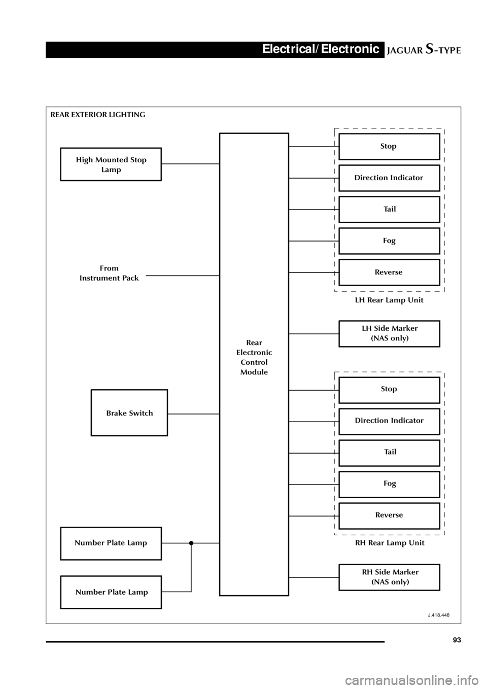
REAR EXTERIOR LIGHTING
Stop
Brake Switch
LH Rear Lamp Unit
Direction Indicator
Tail
Fog
Reverse
Rear
Electronic
Control
Module
High Mounted Stop
Lamp
Number Plate Lamp
LH Side Marker
(NAS only)
Stop
RH Rear Lamp Unit
Direction Indicator
Tail
Fog
Reverse
RH Side Marker
(NAS only)
Number Plate Lamp
From
Instrument Pack
Page 101 of 133
JAGUARS-TYPEElectrical/Electronic
96
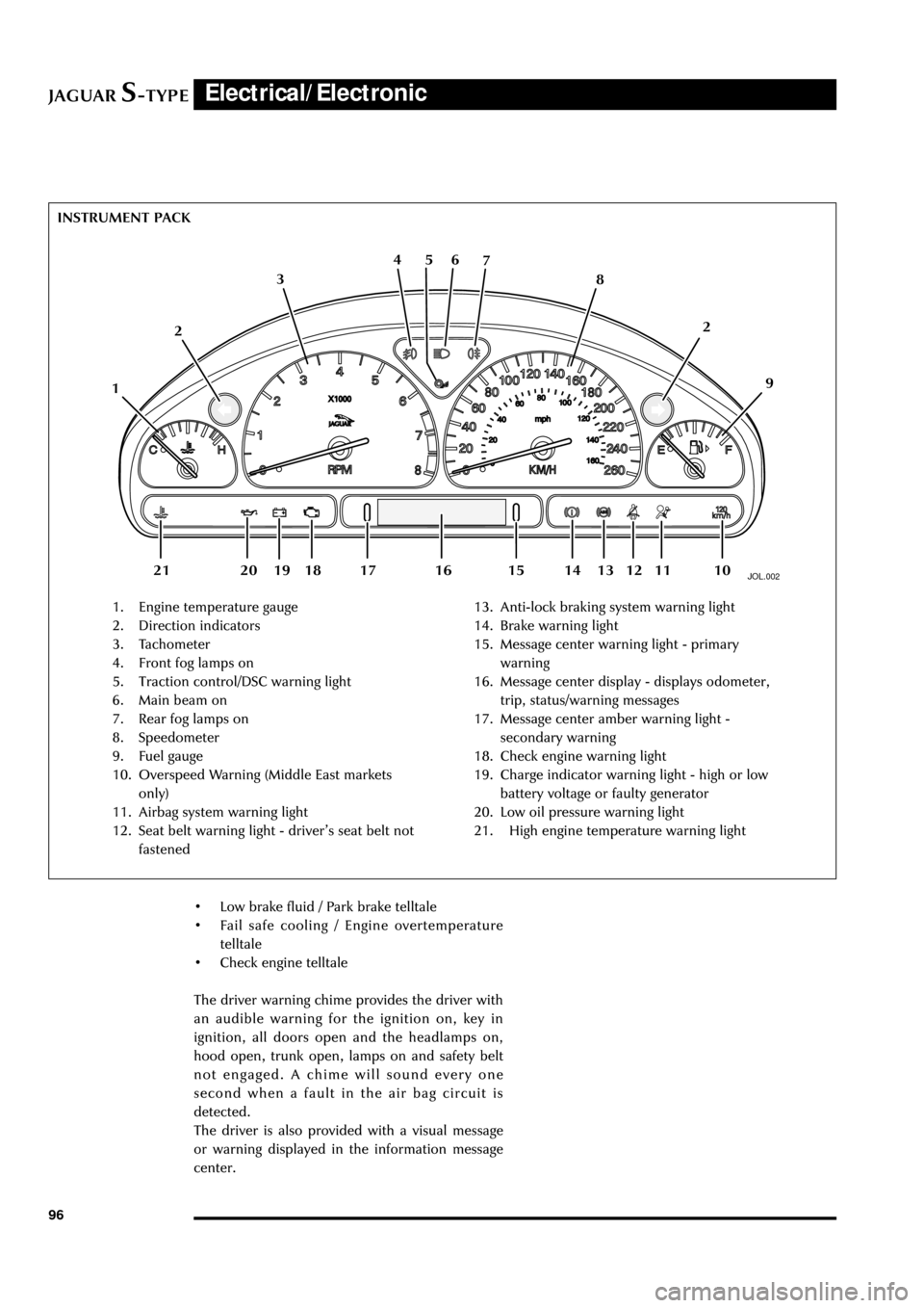
JOL.002
1. Engine temperature gauge
2. Direction indicators
3. Tachometer
4. Front fog lamps on
5. Traction control/DSC warning light
6. Main beam on
7. Rear fog lamps on
8. Speedometer
9. Fuel gauge
10. Overspeed Warning (Middle East markets
only)
11. Airbag system warning light
12. Seat belt warning light - driverÕs seat belt not
fastened13. Anti-lock braking system warning light
14. Brake warning light
15. Message center warning light - primary
warning
16. Message center display - displays odometer,
trip, status/warning messages
17. Message center amber warning light -
secondary warning
18. Check engine warning light
19. Charge indicator warning light - high or low
battery voltage or faulty generator
20. Low oil pressure warning light
21. High engine temperature warning light INSTRUMENT PACK
126 5 4
3
109 8 7
112
13 12 18 20 19 1416 15 17 21
¥ Low brake fluid / Park brake telltale
¥ Fail safe cooling / Engine overtemperature
telltale
¥ Check engine telltale
The driver warning chime provides the driver with
an audible warning for the ignition on, key in
ignition, all doors open and the headlamps on,
hood open, trunk open, lamps on and safety belt
not engaged. A chime will sound every one
second when a fault in the air bag circuit is
detected.
The driver is also provided with a visual message
or warning displayed in the information message
center.
Page 105 of 133
JAGUARS-TYPEElectrical/Electronic
100
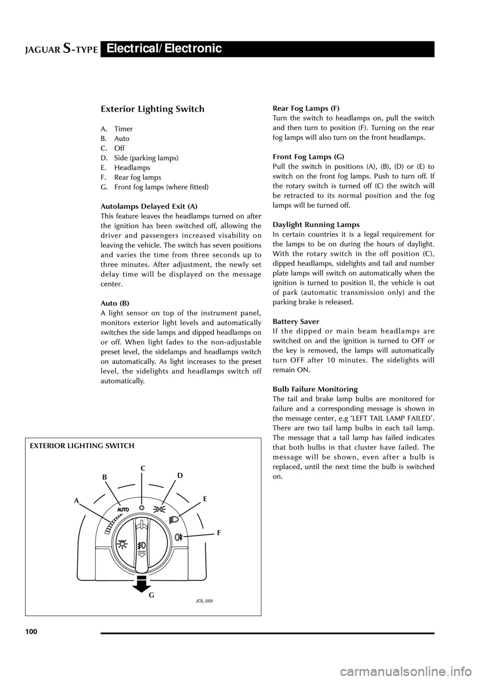
Exterior Lighting Switch
A. Timer
B. Auto
C. Off
D. Side (parking lamps)
E. Headlamps
F. Rear fog lamps
G. Front fog lamps (where fitted)
Autolamps Delayed Exit (A)
This feature leaves the headlamps turned on after
the ignition has been switched off, allowing the
driver and passengers increased visability on
leaving the vehicle. The switch has seven positions
and varies the time from three seconds up to
three minutes. After adjustment, the newly set
delay time will be displayed on the message
center.
Auto (B)
A light sensor on top of the instrument panel,
monitors exterior light levels and automatically
switches the side lamps and dipped headlamps on
or off. When light fades to the non-adjustable
preset level, the sidelamps and headlamps switch
on automatically. As light increases to the preset
level, the sidelights and headlamps switch off
automatically.Rear Fog Lamps (F)
Turn the switch to headlamps on, pull the switch
and then turn to position (F). Turning on the rear
fog lamps will also turn on the front headlamps.
Front Fog Lamps (G)
Pull the switch in positions (A), (B), (D) or (E) to
switch on the front fog lamps. Push to turn off. If
the rotary switch is turned off (C) the switch will
be retracted to its normal position and the fog
lamps will be turned off.
Daylight Running Lamps
In certain countries it is a legal requirement for
the lamps to be on during the hours of daylight.
With the rotary switch in the off position (C),
dipped headlamps, sidelights and tail and number
plate lamps will switch on automatically when the
ignition is turned to position II, the vehicle is out
of park (automatic transmission only) and the
parking brake is released.
Battery Saver
If the dipped or main beam headlamps are
switched on and the ignition is turned to OFF or
the key is removed, the lamps will automatically
turn OFF after 10 minutes. The sidelights will
remain ON.
Bulb Failure Monitoring
The tail and brake lamp bulbs are monitored for
failure and a corresponding message is shown in
the message center, e.g ÔLEFT TAIL LAMP FAILEDÕ.
There are two tail lamp bulbs in each tail lamp.
The message that a tail lamp has failed indicates
that both bulbs in that cluster have failed. The
message will be shown, even after a bulb is
replaced, until the next time the bulb is switched
on.
JOL.069
EXTERIOR LIGHTING SWITCH
A
F E D C
B
G
Page 108 of 133
JAGUARS-TYPEElectrical/Electronic
103 Note: If the switches are held for longer than six
seconds, e.g. when attempting to overcome frozen
or jammed windows, the window drive will be
switched off for a few seconds to protect the
window drive motors.
Memory Setting (where fitted)
The position of the driverÕs seat, steering column
and exterior rear view mirrors can be memorized
and recalled. Two different driving position
profiles can be entered In the memory. The
switches for seat, mirror, steering column
adjustment and memory setting can be operated
with or without the key being in the ignition.
To store a driving position in the memory:
1. Adjust the seat, steering column an exterior
rear view mirrors to the desired position.
2. Push the memory button and the light in the
switch will illuminate
3. Within five seconds, push button Ô1Õ orÕ2Õ to
memorize the configuration. The memory
button light will go out and a chime will
indicate that the setting procedure is
complete. Additionally, if the ignition is on,
the message center will display a message
that the settings have been saved.
To recall a memorized position, the gear selector
lever must be in ÔPÕ or ÔNÕ on automatic
transmission vehicles and the park brake must be
applied on manual transmission vehicles. Press
and release the appropriate memory button (Ô1Õ or
Ô2Õ). The seat, steering column and door mirrors
will move automatically to the memorized
position.
The key ring transmitter can also be set to
memorize the position of the driverÕs seat,
steering column and exterior rear view mirrors.
Memory Recall Using a Key-ring Transmitter
The key-ring transmitter will recall a memory
position when the unlock button is pressed when
set as follows:
Adjust the seat, steering column and exterior rear
view mirrors to the desired position.
Press ÔmemoryÕ button.
Within five seconds, press any button on the key-
ring transmitter.
Press button Ô1Õ or Ô2Õ.
Repeat for the other transmitter, pressing the
remaining memory button.
To cancel key-ring transmitter memory recall:
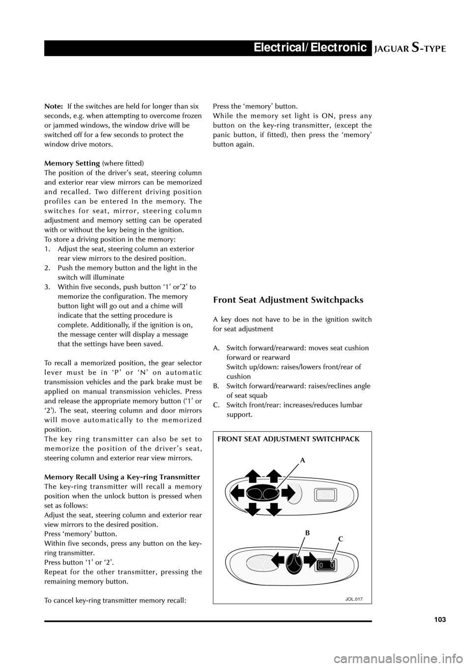
Front Seat Adjustment Switchpacks
A key does not have to be in the ignition switch
for seat adjustment
A. Switch forward/rearward: moves seat cushion
forward or rearward
Switch up/down: raises/lowers front/rear of
cushion
B. Switch forward/rearward: raises/reclines angle
of seat squab
C. Switch front/rear: increases/reduces lumbar
support.
JOL.017
FRONT SEAT ADJUSTMENT SWITCHPACK
A
C B Press the ÔmemoryÕ button.
While the memory set light is ON, press any
button on the key-ring transmitter, (except the
panic button, if fitted), then press the ÔmemoryÕ
button again.
Page 117 of 133
JAGUARS-TYPEElectrical/Electronic
112To Lock the Vehicle and Set Alarm
Press the lock button on the key-ring transmitter,
or put the key in the driverÕs door lock, turn the
key towards the rear of the vehicle and release.
The direction indicators will flash once, the
security light on the top of the fascia will start
flashing and, after twenty seconds, the alarm will
be set.
To Unlock the Vehicle and Disarm the Alarm
System
Press the unlock button on the key-ring
transmitter, or put the key in the driverÕs door
lock, turn the key towards the front of the vehicle
and release.
This unlocks all doors (and luggage compartment)
and turns on the interior lamps for twenty
seconds. The exterior direction indicators give
two flashes as unlocking takes place.
Global Closing
When using global closing, ensure that all
occupants are kept clear of the windows and
sliding roof aperture.
Using the key in the driverÕs door, lock the vehicle
and hold in this position to close all the windows
(and sliding roof, if fitted).
Global Opening
Press and hold the key-ring transmitter unlock
button, or use the key to unlock the vehicle and
hold in this position to open all the windows (and
sliding roof, if fitted).
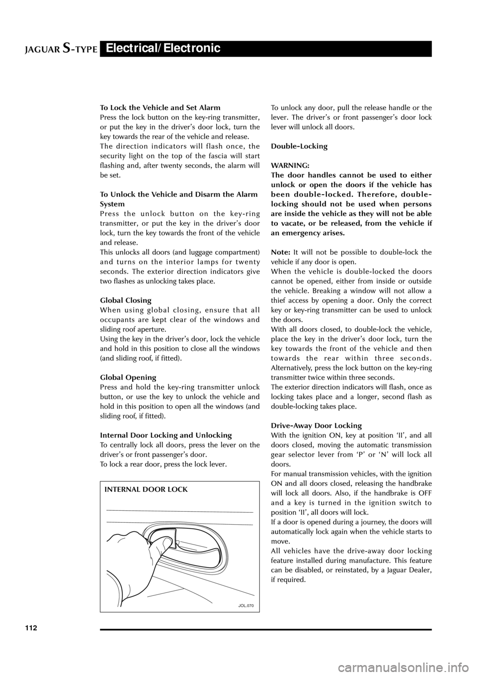
Internal Door Locking and Unlocking
To centrally lock all doors, press the lever on the
driverÕs or front passengerÕs door.
To lock a rear door, press the lock lever.
JOL.070
INTERNAL DOOR LOCKTo unlock any door, pull the release handle or the
lever. The driverÕs or front passengerÕs door lock
lever will unlock all doors.
Double-Locking
WARNING:
The door handles cannot be used to either
unlock or open the doors if the vehicle has
been double-locked. Therefore, double-
locking should not be used when persons
are inside the vehicle as they will not be able
to vacate, or be released, from the vehicle if
an emergency arises.
Note:It will not be possible to double-lock the
vehicle if any door is open.
When the vehicle is double-locked the doors
cannot be opened, either from inside or outside
the vehicle. Breaking a window will not allow a
thief access by opening a door. Only the correct
key or key-ring transmitter can be used to unlock
the doors.
With all doors closed, to double-lock the vehicle,
place the key in the driverÕs door lock, turn the
key towards the front of the vehicle and then
towards the rear within three seconds.
Alternatively, press the lock button on the key-ring
transmitter twice within three seconds.
The exterior direction indicators will flash, once as
locking takes place and a longer, second flash as
double-locking takes place.
Drive-Away Door Locking
With the ignition ON, key at position ÔIIÕ, and all
doors closed, moving the automatic transmission
gear selector lever from ÔPÕ or ÔNÕ will lock all
doors.
For manual transmission vehicles, with the ignition
ON and all doors closed, releasing the handbrake
will lock all doors. Also, if the handbrake is OFF
and a key is turned in the ignition switch to
position ÔIIÕ, all doors will lock.
If a door is opened during a journey, the doors will
automatically lock again when the vehicle starts to
move.
All vehicles have the drive-away door locking
feature installed during manufacture. This feature
can be disabled, or reinstated, by a Jaguar Dealer,
if required.
Page 130 of 133

JAGUARS-TYPEElectrical/Electronic
125
Using the System
Initialization
When the ignition switch is turned to position ÔIIÕ, the initialization of the system is carried out, which
takes a few seconds. When complete, the system is ready to accept voice commands. If the voice
button is pressed before initialization is complete, the message center display will show ÔVOICE NOT
READYÕ.
Audible Feedback, Confirmation & Prompts
For most voice commands, audible feedback of the command, as understood by the system, is available.
Audible feedback may be turned on or off by giving the VOICE FEEDBACK command.
For the phone dial commands, confirmation of the number, before it is dialed, may be turned on or off
by giving the PHONE FEEDBACK command. During some commands for voice training, the user is
prompted by the system to give the next item of information.
For specific operation of all the controls, refer to the OwnerÕs Voice Activation Handbook.
Voice Training
The Voice Activation System is able to interpret most English speakers without difficulty. If, however, it is
found that commands are sometimes not being recognized, the voice training procedure can be carried
out.
Voice Memories
The system has two memories (A and B) for storing the trained voices. The Voice Memory Directory
command provides an indication of the availability of the two voice memories (Full or Available).
Giving Commands after Training
After Voice training the system will automatically recognize a speaker whose voice is held in voice
memory. The system can still be used by other speakers with no loss of response.
Error Messages
In addition to the voice command prompts given by the system, the following error messages may be
encountered. The messages are shown on the message center with voice confirmation (error tone or
voice playback).
Message Explanation
NO SPEECH DETECTED The system did not detect any speech when the voice button
was pressed
NAME TAG TOO LONG A nametag must not take longer than three seconds to say
NAME TAG NOT UNIQUE The nametag (or similar sounding name) has already been
used
COMMAND NOT RECOGNIZED The command was not recognized from the list of voice
commands
HANDBRAKE MUST BE ENGAGED The handbrake must be applied for voice training
RADIO MUST BE IN TUNER MODE The sound system must be in radio mode before giving the
Radio Store command
VOICE NOT READY The voice button was pressed while the voice system was still
initializing
TOO MANY DIGITS The phone number in a Phone Enter command was too long