steering wheel JAGUAR S TYPE 2005 1.G Technical Guide Update
[x] Cancel search | Manufacturer: JAGUAR, Model Year: 2005, Model line: S TYPE, Model: JAGUAR S TYPE 2005 1.GPages: 133, PDF Size: 3.48 MB
Page 72 of 133

JAGUARS-TYPEClimate Control
67 Pipework
The suction hose and liquid line are a one-piece
assembly. A single screw connects them to the air
conditioning unit manifold at the bulkhead. A
further screw fixing and push-in clip secures them
at the side of the engine bay. The liquid line fixed
to the cooling module then joins with a block
fitting and the suction hose connects with a quick
connect fitting and routes across the underneath
of the cooling module to the compressor. The
compressor suction and discharge hoses are also a
one piece assembly.
A pressure transducer is fitted to the discharge
hose as it connects to the rear of the condenser.
The high side charge port is situated on the
manifold connecting to the receiver drier whilst
the low side is adjacent to the compressor behind
the LH front wheel.
The compressor is a 9Occ scroll, which is variable
from 100% to 30%. Compressor is standard
specification to all vehicles although package
makes them unique to V6 and V8.
Air Distribution
Air distribution is as follows:
¥ Defrost duct integral with the fascia.
¥ Face vents, plenum, manifold, centre face
duct, side face duct, side window demist duct
are all sub-assembled into the fascia.
¥ Driver and front seat passenger foot ducts are
installed in the fascia after it has been fitted
to the vehicle.
¥ Rear foot ducts are fitted to the underframe.
¥ Rear face duct fitted to transmission tunnel.
¥ Rear face vent fitted to console.
¥ Extractor boxes fitted in rear quarter panels.
All flaps are electric servo controlled and
comprise:
¥ Fresh/recirculation - heater/evaporator unit.
¥ Cold air bypass - heater/evaporator unit.
¥ Foot flap - mounted on plenum.
¥ Defrost flap - mounted on plenum.
¥ Face flap - mounted on plenum.
Sensors, for operation of the system, are:
¥ Ambient temperature sensor - located behind
the lower front grille.
¥ Solar sensor - fitted to the top centre of the
fascia at the defrost grille
¥ In-car sensor - aspirated from the plenum
venturi sensor mounted inboard of the
steering column.¥ Two heater air outlet sensors
¥ One evaporator air outlet sensor
Servicing
Routine servicing consists of particle filter
replacement.
Replaceable items on the climate control system
are:
¥ Servo complete with linkages
¥ Sensors
¥ Evaporator and seals
¥ Heater core and seals
¥ Blower motor
¥ Impeller/blower motor wheel
¥ Hoses
¥ Registers/vents
¥ Ducts, except the defrost
¥ Defrost and side window demist grilles
¥ Control unit
¥ Compressor
¥ Water pump
¥ Water valve
¥ Receiver/drier
¥ Condenser
There are no panel diagnostics but PDU facility is
available with extensive capability, similar to
current XJ and XK Series.
System refrigerant is R134a. Vehicle charge weight
is 800 gms and charging is through the high side
charge port only.
Oil type is WSH-MIC231-B and refill quantity is
180 cc -220 cc.
Special tools are hose clamp pliers and air-
conditioning hoses spring lock de-coupler.
General information
Ensure that the grille at the base of the windshield
is kept clear of leaves, snow or other obstructions.
A solar sensor is mounted on top of the fascia, in
the centre of the defrost grille, and this should not
be covered.
The air conditioning system should be run briefly
at least once each week with a cold setting to
prevent the seals from drying out with subsequent
refrigerant leaks.
When the engine and vehicle interior are cold the
fan speed may be low until the engine has warmed
up, this avoids excessively cold air being blown
into the cabin.
Page 79 of 133

JAGUARS-TYPEElectrical/Electronic
74The SCP communication network will remain
operational even with severing of one of the bus
wires. Communications will also continue if one
of the bus wires is shorted to ground or battery
positive voltage (B+), or if some , but not all,
termination resistors are lost.
Unlike the SCP communication network, the
ISO 9141 communication network will not
function if the wire is shorted to ground or battery
positive voltage (B+). Also, if one of the modules
on the ISO 9141 network loses power or shorts
internally, communication to that module will fail.
Control Modules
The vehicle control module functions are
described briefly below (for further information
refer to the relevant sections throughout the
Guide).
Anti Lock Brake/Traction Control and
Dynamic Stability Control, Control Modules
The anti-lock brake control module is connected
to the SCP communication network. The module
comes in two forms. The first type is the standard
equipped anti-lock brake system (ABS) with
traction control (TC). It controls the brake
pressure to the four wheels to keep the vehicle
under control while braking.
The second type of ABS is optional and is called
dynamic stability control (DSC). This control
module adds yaw sensors to the package to help
in sensing a loss of vehicle control.
Audio Control Unit
The audio control unit is connected to the SCP
communication network and also to the audio
control protocol (ACP) communication network.
The audio control unit communicates with the
compact disc and the cellular phone transceiver.
Driver Door Control Module (DDCM)
DDCM is connected to the SCP communication
network. The module controls many functions
including power windows, driver mirror, power
locks, and keyless remote entry.Driver Seat Control Module (DSCM)
The DSCM is connected to the SCP
communication network. The DSCM is located
under the driver seat and controls the seat
positions. The module also communicates with the
DDCM to control the driver seat memory
functions.
Control Module Locations
Key to illustration on following page:
1.Anti-lock brake system/Traction control
system or Dynamic stability control
(ABS/TCCM or DSCCM)
(non-handed)
2.Throttle actuator control module (TACM)
(non-handed)
3.Powertrain control module (PCM) (handed)
4.Air conditioning control module (A/CCM)
(non-handed)
5.Restraint control module (RCM) (non-handed)
6.Sliding roof control module (SRCM)
(non-handed)
7.Passenger seat heater control module
(PSHCM) (non-handed)
8.Rear electronic control module (RECM)
(non-handed)
9.Vehicle information control module (VICM)
(Japan only)
10.Adaptive damping control module (ADCM)
(non-handed)
11.Parking aid control module (PACM)
(non-handed)
12.Navigation control module (NCM)
(non-handed)
13.Vehicle emergency control module (VECM)
(non-handed)
14.Voice-activated control module (VACM)
(non-handed)
15.Cellular telephone control module (CTCM)
(non-handed)
16.Driver seat heater control module (DSHCM)
(non-handed)
17.Driver seat control module (DSCM) (handed)
18.Driver door control module (DDCM)
(handed)
19.Instrument pack (handed)
20.General electronics control module (GECM)
(non-handed)
21.Steering column lock module (SCLM) (handed)
Page 102 of 133
JAGUARS-TYPEElectrical/Electronic
97
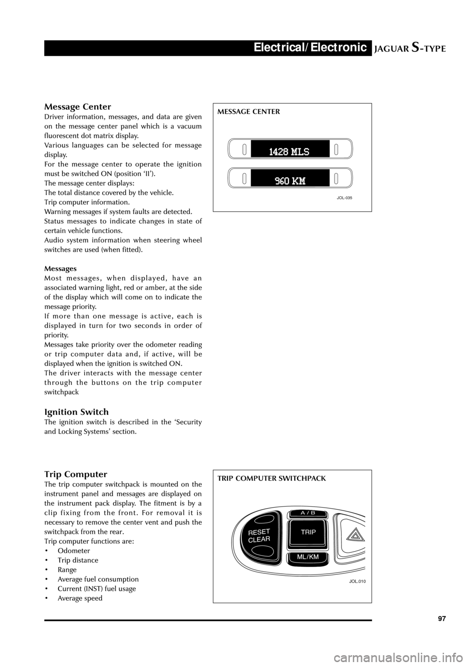
Trip Computer
The trip computer switchpack is mounted on the
instrument panel and messages are displayed on
the instrument pack display. The fitment is by a
clip fixing from the front. For removal it is
necessary to remove the center vent and push the
switchpack from the rear.
Trip computer functions are:
¥ Odometer
¥ Trip distance
¥ Range
¥ Average fuel consumption
¥ Current (INST) fuel usage
¥ Average speed
JOL.010
TRIP COMPUTER SWITCHPACK
Message Center
Driver information, messages, and data are given
on the message center panel which is a vacuum
fluorescent dot matrix display.
Various languages can be selected for message
display.
For the message center to operate the ignition
must be switched ON (position ÔIIÕ).
The message center displays:
The total distance covered by the vehicle.
Trip computer information.
Warning messages if system faults are detected.
Status messages to indicate changes in state of
certain vehicle functions.
Audio system information when steering wheel
switches are used (when fitted).
Messages
Most messages, when displayed, have an
associated warning light, red or amber, at the side
of the display which will come on to indicate the
message priority.
If more than one message is active, each is
displayed in turn for two seconds in order of
priority.
Messages take priority over the odometer reading
or trip computer data and, if active, will be
displayed when the ignition is switched ON.
The driver interacts with the message center
through the buttons on the trip computer
switchpack
Ignition Switch
The ignition switch is described in the ÔSecurity
and Locking SystemsÕ section.
JOL-035
MESSAGE CENTER
Page 103 of 133
JAGUARS-TYPEElectrical/Electronic
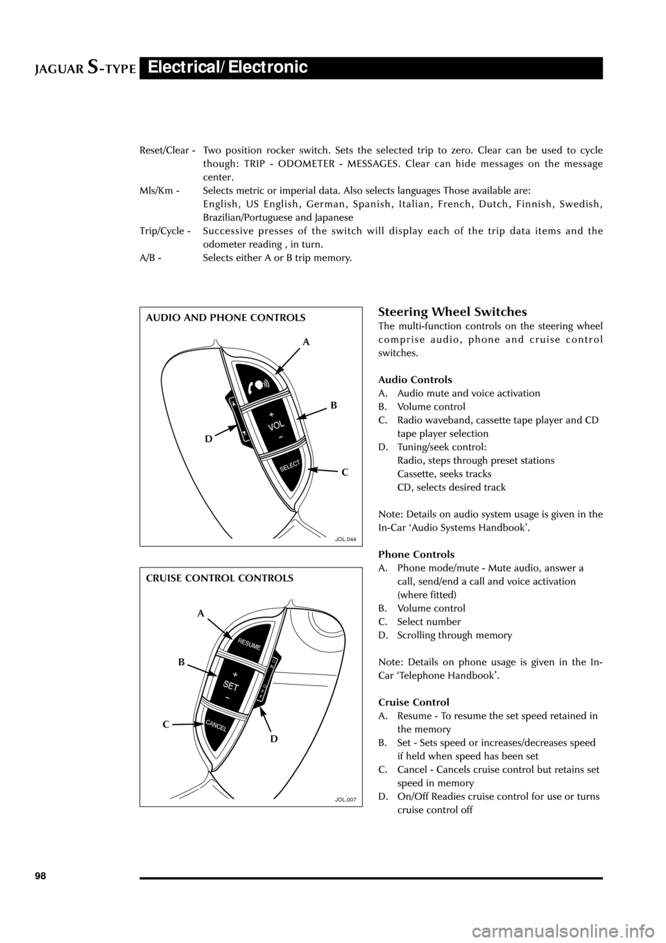
98Reset/Clear - Two position rocker switch. Sets the selected trip to zero. Clear can be used to cycle
though: TRIP - ODOMETER - MESSAGES. Clear can hide messages on the message
center.
Mls/Km - Selects metric or imperial data. Also selects languages Those available are:
English, US English, German, Spanish, Italian, French, Dutch, Finnish, Swedish,
Brazilian/Portuguese and Japanese
Trip/Cycle - Successive presses of the switch will display each of the trip data items and the
odometer reading , in turn.
A/B - Selects either A or B trip memory.
Steering Wheel Switches
The multi-function controls on the steering wheel
comprise audio, phone and cruise control
switches.
Audio Controls
A. Audio mute and voice activation
B. Volume control
C. Radio waveband, cassette tape player and CD
tape player selection
D. Tuning/seek control:
Radio, steps through preset stations
Cassette, seeks tracks
CD, selects desired track
Note: Details on audio system usage is given in the
In-Car ÔAudio Systems HandbookÕ.
Phone Controls
A. Phone mode/mute - Mute audio, answer a
call, send/end a call and voice activation
(where fitted)
B. Volume control
C. Select number
D. Scrolling through memory
Note: Details on phone usage is given in the In-
Car ÔTelephone HandbookÕ.
Cruise Control
A. Resume - To resume the set speed retained in
the memory
B. Set - Sets speed or increases/decreases speed
if held when speed has been set
C. Cancel - Cancels cruise control but retains set
speed in memory
D. On/Off Readies cruise control for use or turns
cruise control off
A
D
C B AUDIO AND PHONE CONTROLS
CRUISE CONTROL CONTROLS
A
D CB
JOL.044
JOL.007
Page 116 of 133
JAGUARS-TYPEElectrical/Electronic
111 Steering Column Lock
The steering column lock is remote from the
ignition switch and controlled electronically.
When the ignition key is removed from the
ignition switch the steering column lock is
engaged. The lock is disengaged when the key is
placed in the ignition switch.
The lock can be clearly heard as it engages and
disengages.
In rare circumstances it may be necessary to
gently turn the steering wheel from side to side to
release the steering column lock.
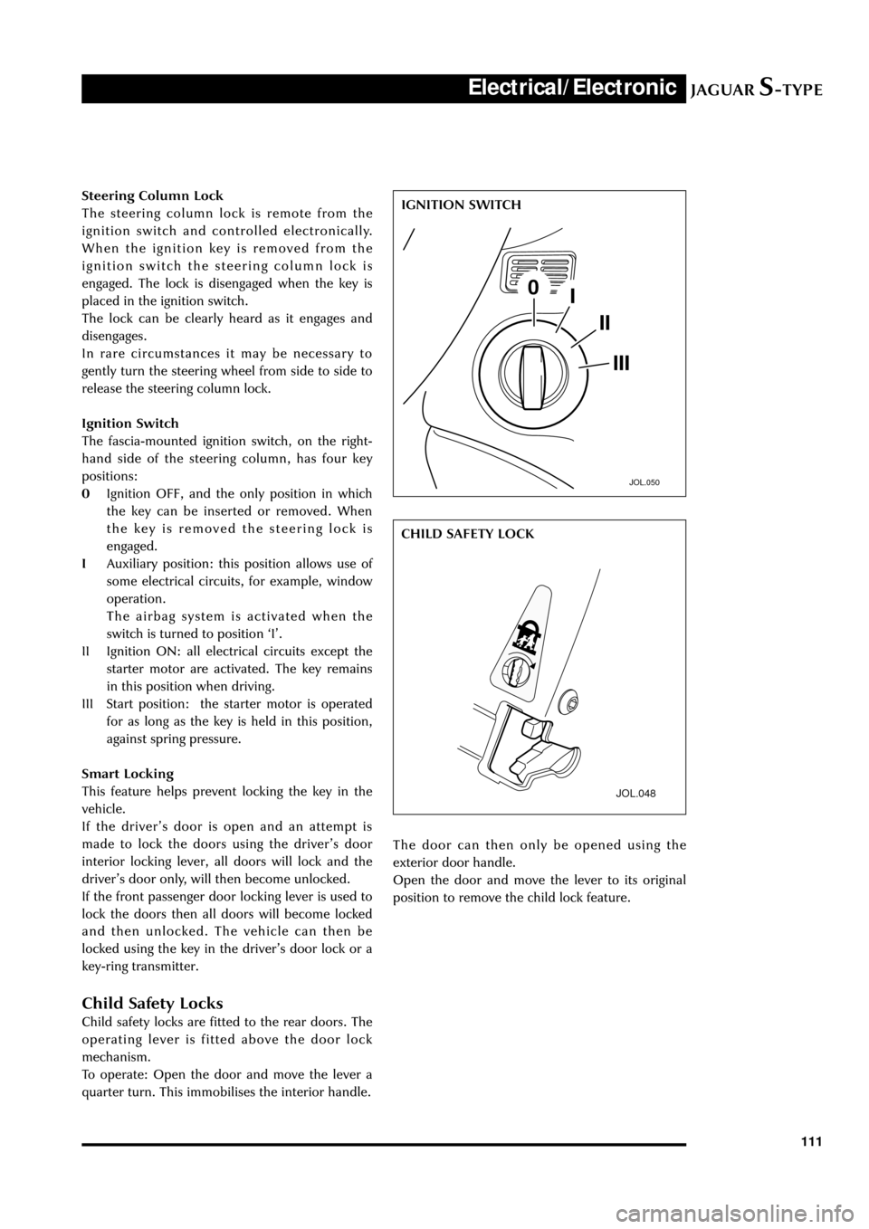
Ignition Switch
The fascia-mounted ignition switch, on the right-
hand side of the steering column, has four key
positions:
0Ignition OFF, and the only position in which
the key can be inserted or removed. When
the key is removed the steering lock is
engaged.
IAuxiliary position: this position allows use of
some electrical circuits, for example, window
operation.
The airbag system is activated when the
switch is turned to position ÔIÕ.
II Ignition ON: all electrical circuits except the
starter motor are activated. The key remains
in this position when driving.
III Start position: the starter motor is operated
for as long as the key is held in this position,
against spring pressure.
Smart Locking
This feature helps prevent locking the key in the
vehicle.
If the driverÕs door is open and an attempt is
made to lock the doors using the driverÕs door
interior locking lever, all doors will lock and the
driverÕs door only, will then become unlocked.
If the front passenger door locking lever is used to
lock the doors then all doors will become locked
and then unlocked. The vehicle can then be
locked using the key in the driverÕs door lock or a
key-ring transmitter.
Child Safety Locks
Child safety locks are fitted to the rear doors. The
operating lever is fitted above the door lock
mechanism.
To operate: Open the door and move the lever a
quarter turn. This immobilises the interior handle.
JOL.050
IGNITION SWITCH
JOL.048
The door can then only be opened using the
exterior door handle.
Open the door and move the lever to its original
position to remove the child lock feature.CHILD SAFETY LOCK
Page 121 of 133
JAGUARS-TYPEElectrical/Electronic
116
Audio and Communications System
General
The Jaguar sound system is available in two
versions: the Base System and the Premium
System. The audio head unit with integral
amplifier is located in the center stack. The audio
system has a phone interface to access stored
numbers. The antenna module is located on the
vertical panel under the rear parcel shelf
(accessed from the LHS of the trunk), FM and AM
antenna elements are in the rear screen. Four
twin cone 5in x 7in (127mm x 178mm) door
speakers are a modular cassette type for ease of
assembly/disassembly. The assembly consists of a
driverÕs door module (driverÕs door only), speaker,
and wiring and is mounted to the inner door
moulding. A special seal is kept under tension to
avoid water ingress.
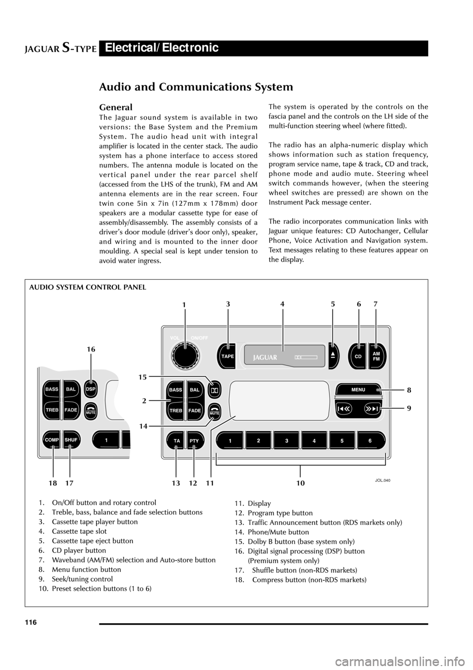
JOL.040
1. On/Off button and rotary control
2. Treble, bass, balance and fade selection buttons
3. Cassette tape player button
4. Cassette tape slot
5. Cassette tape eject button
6. CD player button
7. Waveband (AM/FM) selection and Auto-store button
8. Menu function button
9. Seek/tuning control
10. Preset selection buttons (1 to 6)11. Display
12. Program type button
13. Traffic Announcement button (RDS markets only)
14. Phone/Mute button
15. Dolby B button (base system only)
16. Digital signal processing (DSP) button
(Premium system only)
17. Shuffle button (non-RDS markets)
18. Compress button (non-RDS markets)The system is operated by the controls on the
fascia panel and the controls on the LH side of the
multi-function steering wheel (where fitted).
The radio has an alpha-numeric display which
shows information such as station frequency,
program service name, tape & track, CD and track,
phone mode and audio mute. Steering wheel
switch commands however, (when the steering
wheel switches are pressed) are shown on the
Instrument Pack message center.
The radio incorporates communication links with
Jaguar unique features: CD Autochanger, Cellular
Phone, Voice Activation and Navigation system.
Text messages relating to these features appear on
the display.
1
26 5 4 3
109 8 7
11 13 12 1814 16
15
17 AUDIO SYSTEM CONTROL PANEL
Page 122 of 133
JAGUARS-TYPEElectrical/Electronic
117 The radio volume is muted to a low level when:
the Reverse Park Control is enabled by engaging
reverse gear, the Cellular phone in hands-free
mode is used, the Navigation system delivers
audible route guidance instructions or the Voice
activation system requests listening or verbal
feedback.
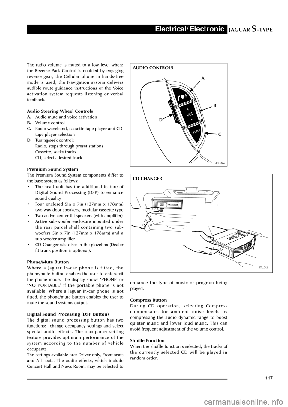
Audio Steering Wheel Controls
A.Audio mute and voice activation
B.Volume control
C.Radio waveband, cassette tape player and CD
tape player selection
D.Tuning/seek control:
Radio, steps through preset stations
Cassette, seeks tracks
CD, selects desired track
Premium Sound System
The Premium Sound System components differ to
the base system as follows:
¥ The head unit has the additional feature of
Digital Sound Processing (DSP) to enhance
sound quality
¥ Four enclosed 5in x 7in (127mm x 178mm)
two way door speakers, modular cassette type
¥ Two active center fill speakers (with amplifier)
¥ Active sub-woofer enclosure mounted under
the rear parcel shelf containing two sub-
woofers 5in x 7in (127mm x 178mm) and a
sub-woofer amplifier
¥ CD Changer (six disc) in the glovebox (Dealer
fit trunk position is optional).
Phone/Mute Button
Where a Jaguar in-car phone is fitted, the
phone/mute button enables the user to enter/exit
the phone mode. The display shows ÔPHONEÕ or
ÔNO PORTABLEÕ if the portable phone is not
available. Where a Jaguar in-car phone is not
fitted, the phone/mute button enables the user to
mute the sound systems output.
Digital Sound Processing (DSP Button)
The digital sound processing button has two
functions: change occupancy settings and select
special audio effects. The occupancy setting
feature provides optimum performance of the
system according to the number of vehicle
occupants.
The settings available are: Driver only, Front seats
and All seats. The audio effects, which include
Concert Hall and News Room, may be selected to
JOL.042
enhance the type of music or program being
played.
Compress Button
During CD operation, selecting Compress
compensates for ambient noise levels by
compressing the audio dynamic range to boost
quieter music and lower loud music. This can
avoid frequent adjustment of the volume control.
Shuffle Function
When the shuffle function s selected, the tracks of
the currently selected CD will be played in
random order.
A
D
C B AUDIO CONTROLS
CD CHANGER
JOL.044
Page 124 of 133
JAGUARS-TYPEElectrical/Electronic
119
In-Car Telephone
Overview
For markets other than North America, the phone
system uses the Motorolar StarTAC 130 platform
on the GSM cellular transmission network. The
Motorola LCPC platform on the AMPS cellular
transmission network is used for the North
American market. The phone system is a cordless
portable and a hands-free installation. The
installation on the GSM cellular system is offered
as a factory fit option or Dealer fit aftermarket
accessory; on the AMPS cellular system it is
Dealer fit only.
For hands-free operation, the phone handset is
connected to the in-car installation. This provides
a directional microphone located on the
headlining (see page 124), an external aerial
mounted on the rear screen and connection to
the vehicle sound system.
The phone is operated by audio head unit
controls, the controls on the LH side of the
steering wheel (where fitted) or the handset. The
system includes an interface to the Voice
activation Control, where fitted. Messages relating
to the phone are shown on the sound system
display when the phone system is active. The
phone and ringer sound output can be adjusted
using the sound system volume control. For
specific operation of all the controls refer to the
OwnerÕs In-Car Telephone Handbook.
Unless the vehicle is fitted with the Jaguar
Navigation System, the portable is installed in the
center console storage compartment.
There are two dedicated locations for the phone
installation: in the Center Stack or the Center
Console Cubby Box depending on the optional
fitment of the Navigation System.
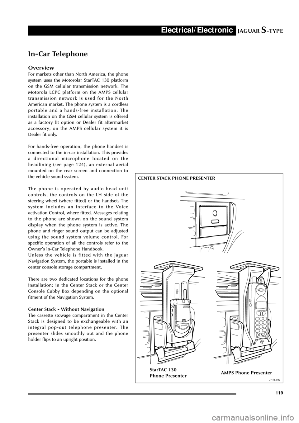
Center Stack - Without Navigation
The cassette stowage compartment in the Center
Stack is designed to be exchangeable with an
integral pop-out telephone presenter. The
presenter slides smoothly out and the phone
holder flips to an upright position.
J.415.039
CENTER STACK PHONE PRESENTER
StarTAC 130
Phone PresenterAMPS Phone Presenter
J.415.039
Page 129 of 133
JAGUARS-TYPEElectrical/Electronic
124
Voice Activation
JOL.275
General
Voice Activation, currently available in a limited
number of markets, provides a convenient way of
controlling the following vehicle systems (where
fitted):
¥ Sound System (radio, cassette tape player and
CD player)
¥ In-car Telephone
¥ Climate Control System.
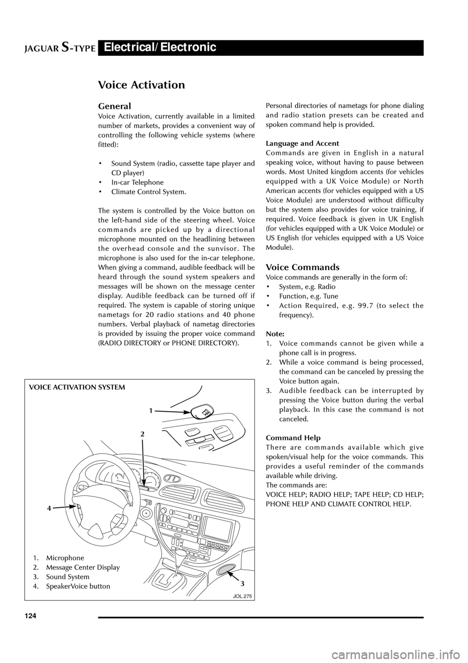
The system is controlled by the Voice button on
the left-hand side of the steering wheel. Voice
commands are picked up by a directional
microphone mounted on the headlining between
the overhead console and the sunvisor. The
microphone is also used for the in-car telephone.
When giving a command, audible feedback will be
heard through the sound system speakers and
messages will be shown on the message center
display. Audible feedback can be turned off if
required. The system is capable of storing unique
nametags for 20 radio stations and 40 phone
numbers. Verbal playback of nametag directories
is provided by issuing the proper voice command
(RADIO DIRECTORY or PHONE DIRECTORY).Personal directories of nametags for phone dialing
and radio station presets can be created and
spoken command help is provided.
Language and Accent
Commands are given in English in a natural
speaking voice, without having to pause between
words. Most United kingdom accents (for vehicles
equipped with a UK Voice Module) or North
American accents (for vehicles equipped with a US
Voice Module) are understood without difficulty
but the system also provides for voice training, if
required. Voice feedback is given in UK English
(for vehicles equipped with a UK Voice Module) or
US English (for vehicles equipped with a US Voice
Module).
Voice Commands
Voice commands are generally in the form of:
¥ System, e.g. Radio
¥ Function, e.g. Tune
¥ Action Required, e.g. 99.7 (to select the
frequency).
Note:
1. Voice commands cannot be given while a
phone call is in progress.
2. While a voice command is being processed,
the command can be canceled by pressing the
Voice button again.
3. Audible feedback can be interrupted by
pressing the Voice button during the verbal
playback. In this case the command is not
canceled.
Command Help
There are commands available which give
spoken/visual help for the voice commands. This
provides a useful reminder of the commands
available while driving.
The commands are:
VOICE HELP; RADIO HELP; TAPE HELP; CD HELP;
PHONE HELP AND CLIMATE CONTROL HELP.
1. Microphone
2. Message Center Display
3. Sound System
4. SpeakerVoice button
1
3
4
VOICE ACTIVATION SYSTEM
2