battery JAGUAR S TYPE 2005 1.G Technical Guide Update
[x] Cancel search | Manufacturer: JAGUAR, Model Year: 2005, Model line: S TYPE, Model: JAGUAR S TYPE 2005 1.GPages: 133, PDF Size: 3.48 MB
Page 17 of 133
JAGUARS-TYPEBody
12
Front and Centre Floor Pan
The floor pan is a three-piece construction with
handed dash panels, welded front suspension
housing, an integral centre bearing panel for the
driveshaft and a large under-tunnel heatshield.
Rear Floor Pan
Multi-piece floor pan design, the rear tub is
designed to accept either a full size or space saver
spare wheel and the luggage compartment has
four tie-down luggage loops. Two plastic covers
are located under the rear seat and these give
easy access to the fuel tank mounted components.
A plastic battery tray is located below the luggage
load floor.
Roof
Provision has been made for roof rack fixings and
the roof has reinforcement for vehicles fitted with
a the sliding roof.
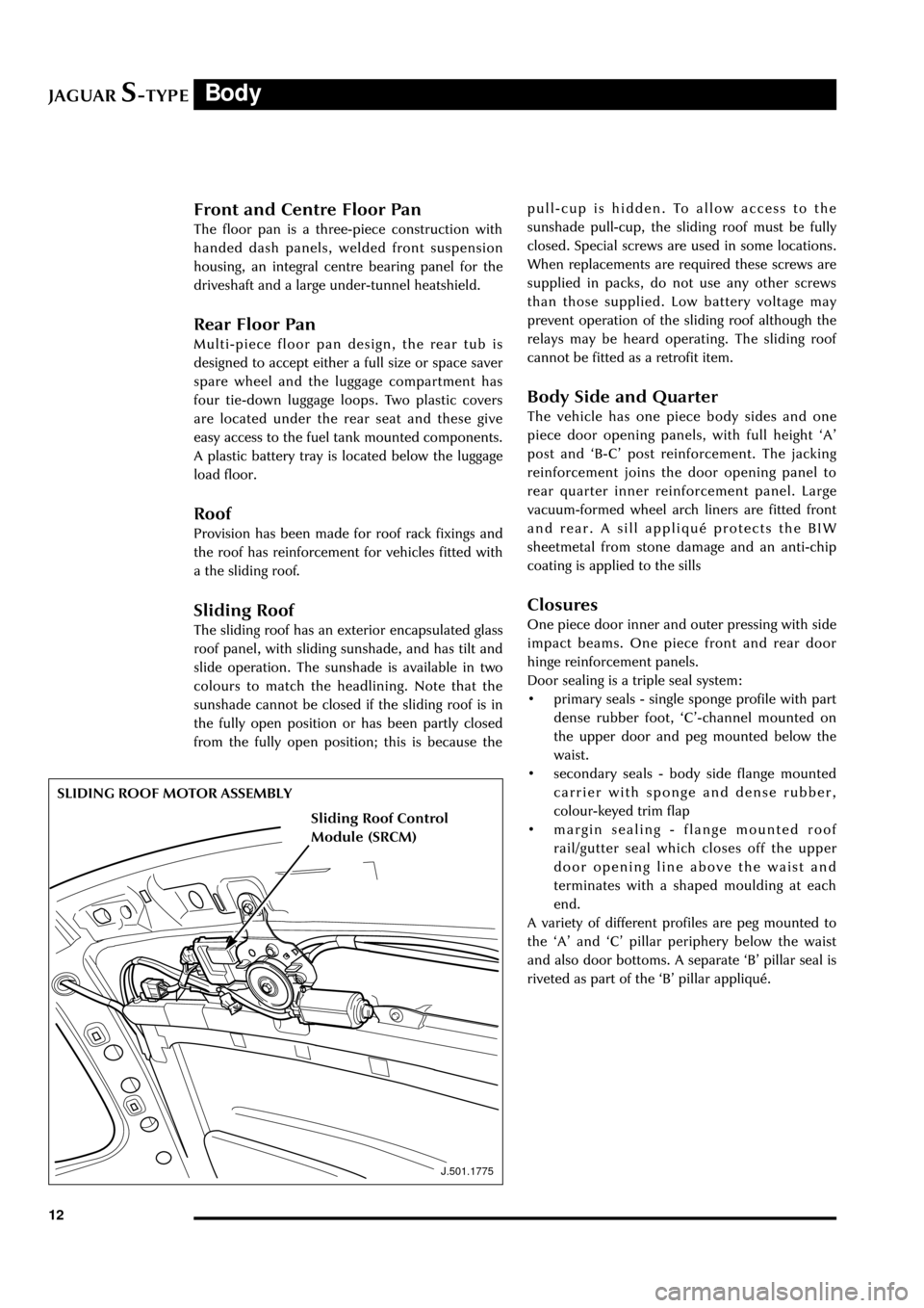
Sliding Roof
The sliding roof has an exterior encapsulated glass
roof panel, with sliding sunshade, and has tilt and
slide operation. The sunshade is available in two
colours to match the headlining. Note that the
sunshade cannot be closed if the sliding roof is in
the fully open position or has been partly closed
from the fully open position; this is because the
J.501.1775
SLIDING ROOF MOTOR ASSEMBLYpull-cup is hidden. To allow access to the
sunshade pull-cup, the sliding roof must be fully
closed. Special screws are used in some locations.
When replacements are required these screws are
supplied in packs, do not use any other screws
than those supplied. Low battery voltage may
prevent operation of the sliding roof although the
relays may be heard operating. The sliding roof
cannot be fitted as a retrofit item.
Body Side and Quarter
The vehicle has one piece body sides and one
piece door opening panels, with full height ÔAÕ
post and ÔB-CÕ post reinforcement. The jacking
reinforcement joins the door opening panel to
rear quarter inner reinforcement panel. Large
vacuum-formed wheel arch liners are fitted front
and rear. A sill appliquŽ protects the BIW
sheetmetal from stone damage and an anti-chip
coating is applied to the sills
Closures
One piece door inner and outer pressing with side
impact beams. One piece front and rear door
hinge reinforcement panels.
Door sealing is a triple seal system:
¥ primary seals - single sponge profile with part
dense rubber foot, ÔCÕ-channel mounted on
the upper door and peg mounted below the
waist.
¥ secondary seals - body side flange mounted
carrier with sponge and dense rubber,
colour-keyed trim flap
¥ margin sealing - flange mounted roof
rail/gutter seal which closes off the upper
door opening line above the waist and
terminates with a shaped moulding at each
end.
A variety of different profiles are peg mounted to
the ÔAÕ and ÔCÕ pillar periphery below the waist
and also door bottoms. A separate ÔBÕ pillar seal is
riveted as part of the ÔBÕ pillar appliquŽ.
Sliding Roof Control
Module (SRCM)
Page 21 of 133
JAGUARS-TYPEBody
16
Cool Air Inlet
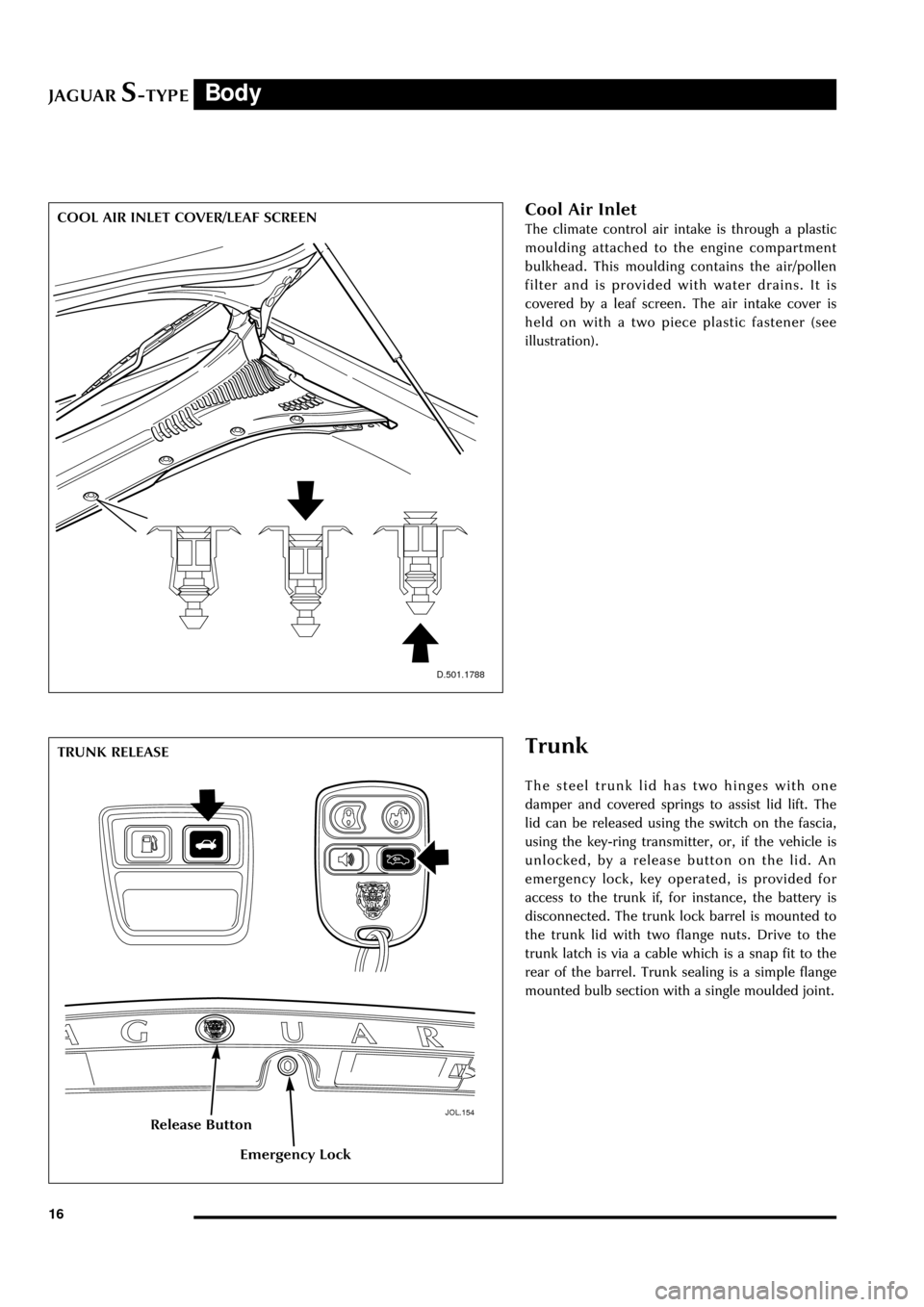
The climate control air intake is through a plastic
moulding attached to the engine compartment
bulkhead. This moulding contains the air/pollen
filter and is provided with water drains. It is
covered by a leaf screen. The air intake cover is
held on with a two piece plastic fastener (see
illustration).
D.501.1788
Trunk
The steel trunk lid has two hinges with one
damper and covered springs to assist lid lift. The
lid can be released using the switch on the fascia,
using the key-ring transmitter, or, if the vehicle is
unlocked, by a release button on the lid. An
emergency lock, key operated, is provided for
access to the trunk if, for instance, the battery is
disconnected. The trunk lock barrel is mounted to
the trunk lid with two flange nuts. Drive to the
trunk latch is via a cable which is a snap fit to the
rear of the barrel. Trunk sealing is a simple flange
mounted bulb section with a single moulded joint.
JOL.154
TRUNK RELEASE
Release Button
Emergency Lock
COOL AIR INLET COVER/LEAF SCREEN
Page 41 of 133
JAGUARS-TYPE
D.418.233
Occupant Protection
36
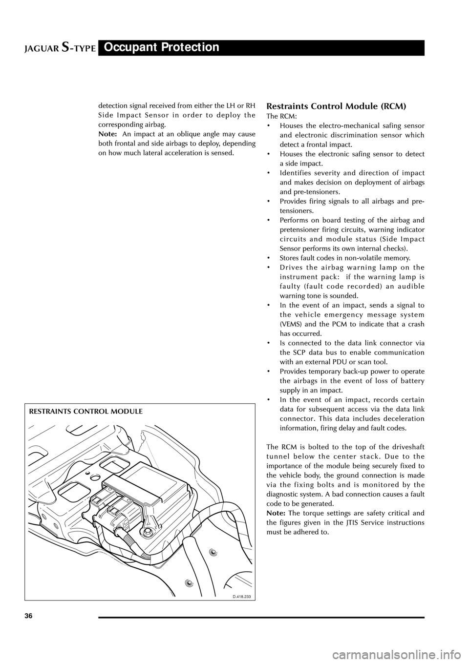
Restraints Control Module (RCM)
The RCM:
¥ Houses the electro-mechanical safing sensor
and electronic discrimination sensor which
detect a frontal impact.
¥ Houses the electronic safing sensor to detect
a side impact.
¥ Identifies severity and direction of impact
and makes decision on deployment of airbags
and pre-tensioners.
¥ Provides firing signals to all airbags and pre-
tensioners.
¥ Performs on board testing of the airbag and
pretensioner firing circuits, warning indicator
circuits and module status (Side Impact
Sensor performs its own internal checks).
¥ Stores fault codes in non-volatile memory.
¥ Drives the airbag warning lamp on the
instrument pack: if the warning lamp is
faulty (fault code recorded) an audible
warning tone is sounded.
¥ In the event of an impact, sends a signal to
the vehicle emergency message system
(VEMS) and the PCM to indicate that a crash
has occurred.
¥ Is connected to the data link connector via
the SCP data bus to enable communication
with an external PDU or scan tool.
¥ Provides temporary back-up power to operate
the airbags in the event of loss of battery
supply in an impact.
¥ In the event of an impact, records certain
data for subsequent access via the data link
connector. This data includes deceleration
information, firing delay and fault codes.
The RCM is bolted to the top of the driveshaft
tunnel below the center stack. Due to the
importance of the module being securely fixed to
the vehicle body, the ground connection is made
via the fixing bolts and is monitored by the
diagnostic system. A bad connection causes a fault
code to be generated.
Note:The torque settings are safety critical and
the figures given in the JTIS Service instructions
must be adhered to. RESTRAINTS CONTROL MODULE
D.418.233
detection signal received from either the LH or RH
Side Impact Sensor in order to deploy the
corresponding airbag.
Note:An impact at an oblique angle may cause
both frontal and side airbags to deploy, depending
on how much lateral acceleration is sensed.
Page 73 of 133

JAGUARS-TYPEClimate Control
68Heated wiper park or (where optionally fitted)
heated front screen.
With the engine running, due to the high current
draw, press to switch on the heated wiper park to
defrost the wiper park area, or where fitted, press
to switch on the heated front screen for rapid
defrost/demist.
Heated wiper park automatically operates in cold
weather, and may stay on continuously. It is
automatically switched on when ÔDEFROSTÕ is
selected. If manually selected, the heated wiper
park will automatically switch off after 10
minutes.
Heated front screen is automatically switched on
when ÔDEFROSTÕ is selected. It will automatically
switch off after 4 minutes. The heaters will switch
off, or not operate, if low battery voltage is
detected.
Heated Rear Screen
With the engine running due to the high current
draw, press to switch on the heated rear screen
for rapid defrost/demist. The rear screen heater
will be automatically switched off after 10
minutes.
In cold conditions, the heated rear screen
operates automatically. Selecting ÔDEFROSTÕ will
also turn the heated rear screen ON. The heaters
will switch off, or not operate, if low battery
voltage is detected.
Air Distribution
Air distribution is automatically controlled when
ÔAUTOÕ is selected. Manual control can be
achieved using the air distribution buttons.
Heat at Rest Feature (V8 engine vehicles
only)
Interior heating may be continued after the
engine has been switched off by turning the
ignition to position ÔIIÕ. The climate control system
will continue to provide heat to the vehicle
interior until the engine cools down. Excessive use
will cause a low battery voltage, which may
prevent the vehicle from being started.
Voice Activated Control
Some functions of the climate control system can
be operated with the Voice Activation System
(when fitted).
A full operating description is given in the Voice
Activation Handbook included with the vehicle
literature pack.
Page 74 of 133
JAGUARS-TYPEElectrical/Electronic
69
Power Distribution
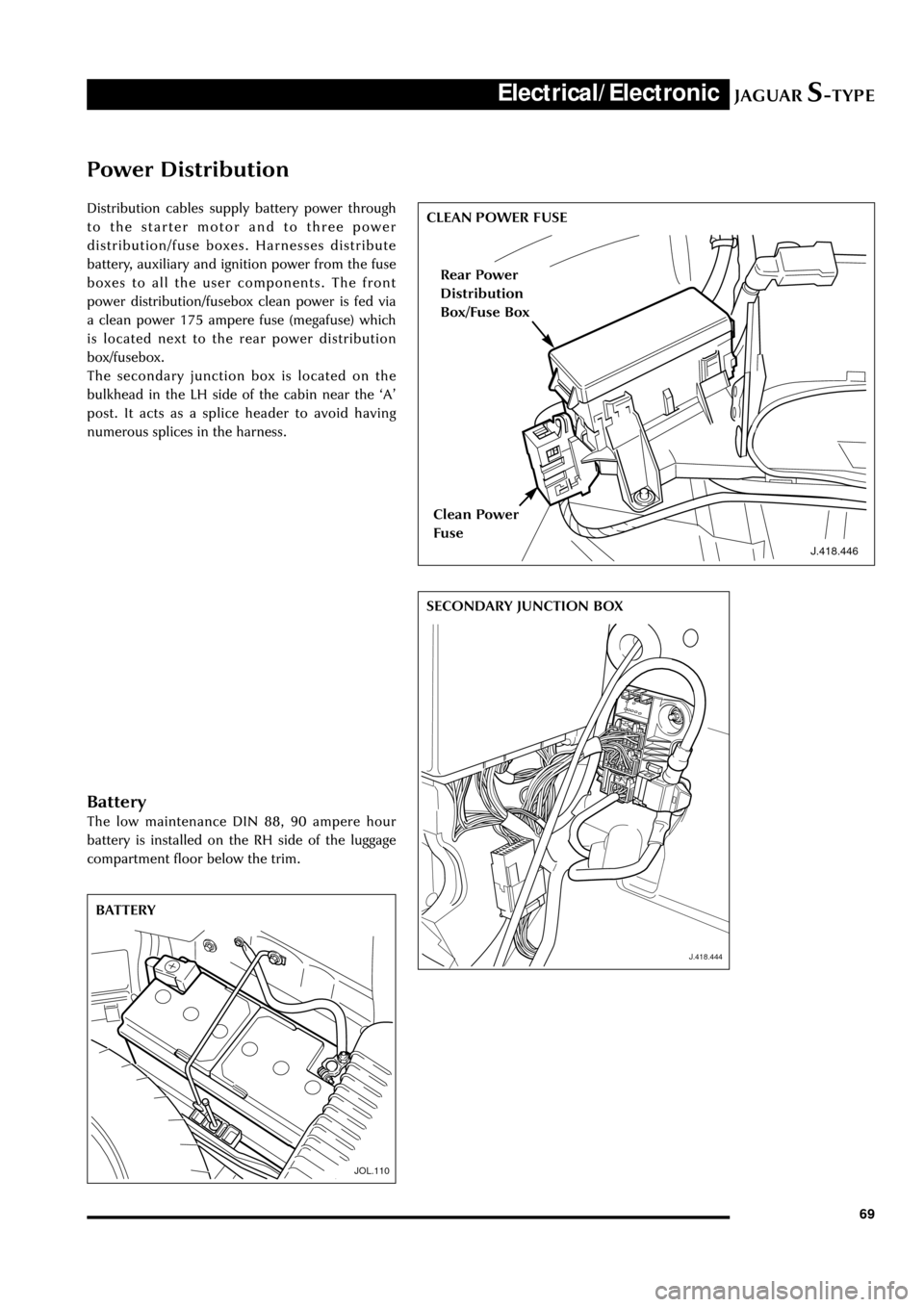
Distribution cables supply battery power through
to the starter motor and to three power
distribution/fuse boxes. Harnesses distribute
battery, auxiliary and ignition power from the fuse
boxes to all the user components. The front
power distribution/fusebox clean power is fed via
a clean power 175 ampere fuse (megafuse) which
is located next to the rear power distribution
box/fusebox.
The secondary junction box is located on the
bulkhead in the LH side of the cabin near the ÔAÕ
post. It acts as a splice header to avoid having
numerous splices in the harness.
J.418.446
CLEAN POWER FUSE
J.418.444
SECONDARY JUNCTION BOX
JOL.110
BATTERY
Rear Power
Distribution
Box/Fuse Box
Clean Power
Fuse
Battery
The low maintenance DIN 88, 90 ampere hour
battery is installed on the RH side of the luggage
compartment floor below the trim.
Page 75 of 133
JAGUARS-TYPEElectrical/Electronic
70
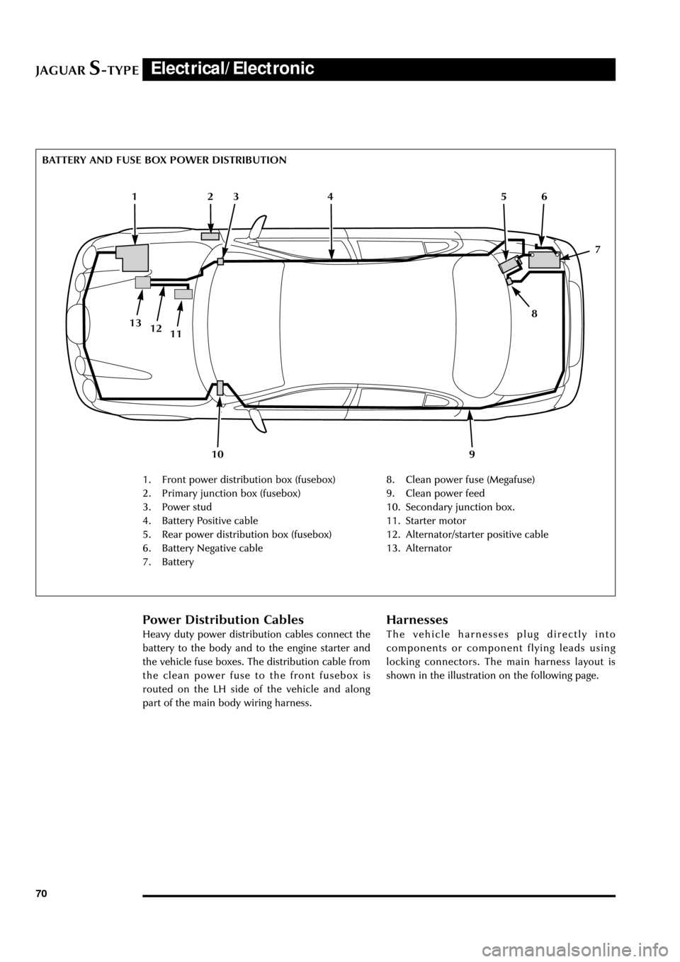
BATTERY AND FUSE BOX POWER DISTRIBUTION
1. Front power distribution box (fusebox)
2. Primary junction box (fusebox)
3. Power stud
4. Battery Positive cable
5. Rear power distribution box (fusebox)
6. Battery Negative cable
7. Battery8. Clean power fuse (Megafuse)
9. Clean power feed
10. Secondary junction box.
11. Starter motor
12. Alternator/starter positive cable
13. Alternator
Power Distribution Cables
Heavy duty power distribution cables connect the
battery to the body and to the engine starter and
the vehicle fuse boxes. The distribution cable from
the clean power fuse to the front fusebox is
routed on the LH side of the vehicle and along
part of the main body wiring harness.
Harnesses
The vehicle harnesses plug directly into
components or component flying leads using
locking connectors. The main harness layout is
shown in the illustration on the following page.
12
10
4
1113
3
9
8
65
7
12
Page 77 of 133
JAGUARS-TYPEElectrical/Electronic
72
Module Communications Network
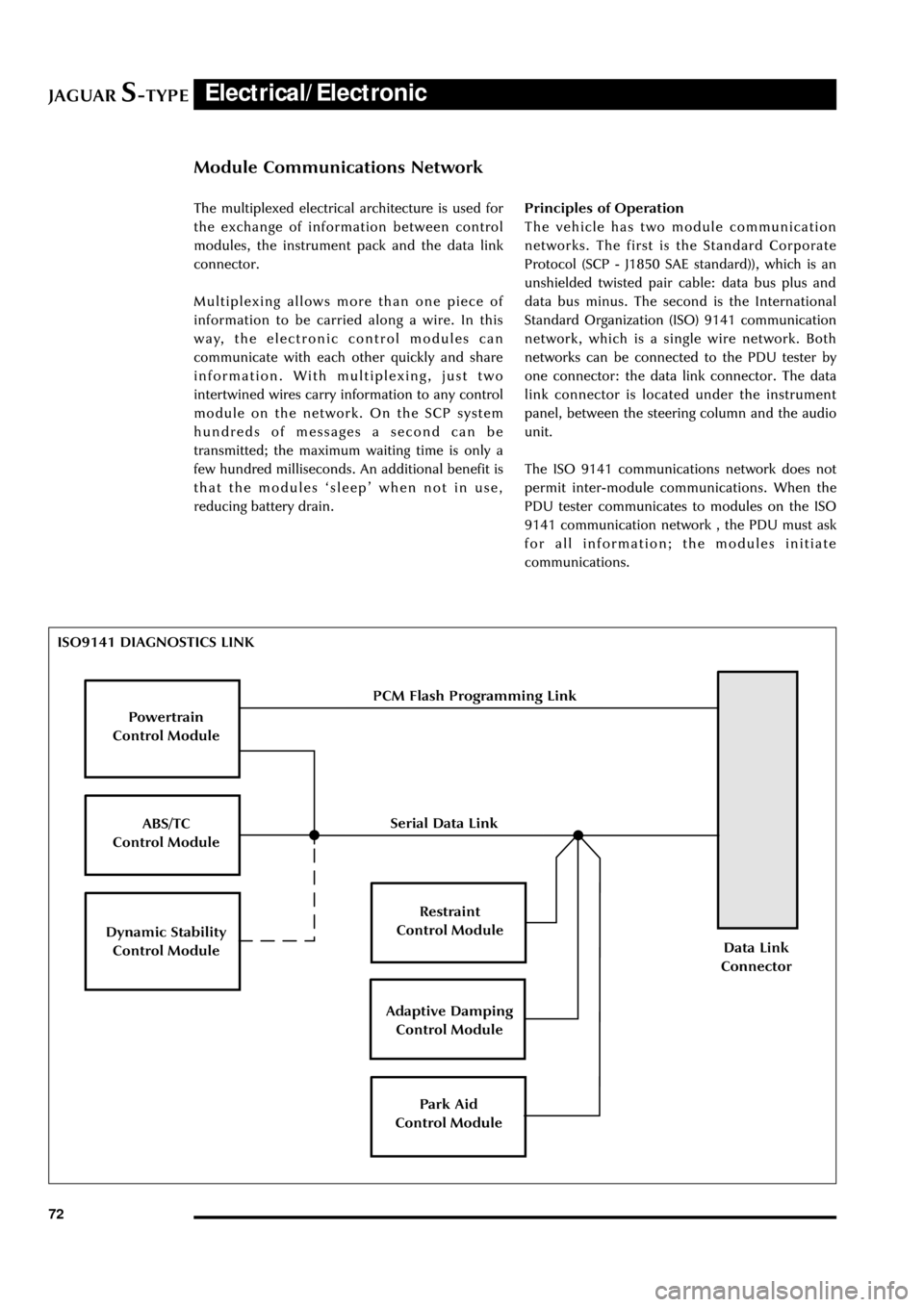
ISO9141 DIAGNOSTICS LINK
Powertrain
Control Module
ABS/TC
Control Module
Dynamic Stability
Control Module
Restraint
Control Module
Adaptive Damping
Control Module
Park Aid
Control Module
Data Link
Connector
PCM Flash Programming Link
Serial Data Link The multiplexed electrical architecture is used for
the exchange of information between control
modules, the instrument pack and the data link
connector.
Multiplexing allows more than one piece of
information to be carried along a wire. In this
way, the electronic control modules can
communicate with each other quickly and share
information. With multiplexing, just two
intertwined wires carry information to any control
module on the network. On the SCP system
hundreds of messages a second can be
transmitted; the maximum waiting time is only a
few hundred milliseconds. An additional benefit is
that the modules ÔsleepÕ when not in use,
reducing battery drain.Principles of Operation
The vehicle has two module communication
networks. The first is the Standard Corporate
Protocol (SCP - J1850 SAE standard)), which is an
unshielded twisted pair cable: data bus plus and
data bus minus. The second is the International
Standard Organization (ISO) 9141 communication
network, which is a single wire network. Both
networks can be connected to the PDU tester by
one connector: the data link connector. The data
link connector is located under the instrument
panel, between the steering column and the audio
unit.
The ISO 9141 communications network does not
permit inter-module communications. When the
PDU tester communicates to modules on the ISO
9141 communication network , the PDU must ask
for all information; the modules initiate
communications.
Page 79 of 133

JAGUARS-TYPEElectrical/Electronic
74The SCP communication network will remain
operational even with severing of one of the bus
wires. Communications will also continue if one
of the bus wires is shorted to ground or battery
positive voltage (B+), or if some , but not all,
termination resistors are lost.
Unlike the SCP communication network, the
ISO 9141 communication network will not
function if the wire is shorted to ground or battery
positive voltage (B+). Also, if one of the modules
on the ISO 9141 network loses power or shorts
internally, communication to that module will fail.
Control Modules
The vehicle control module functions are
described briefly below (for further information
refer to the relevant sections throughout the
Guide).
Anti Lock Brake/Traction Control and
Dynamic Stability Control, Control Modules
The anti-lock brake control module is connected
to the SCP communication network. The module
comes in two forms. The first type is the standard
equipped anti-lock brake system (ABS) with
traction control (TC). It controls the brake
pressure to the four wheels to keep the vehicle
under control while braking.
The second type of ABS is optional and is called
dynamic stability control (DSC). This control
module adds yaw sensors to the package to help
in sensing a loss of vehicle control.
Audio Control Unit
The audio control unit is connected to the SCP
communication network and also to the audio
control protocol (ACP) communication network.
The audio control unit communicates with the
compact disc and the cellular phone transceiver.
Driver Door Control Module (DDCM)
DDCM is connected to the SCP communication
network. The module controls many functions
including power windows, driver mirror, power
locks, and keyless remote entry.Driver Seat Control Module (DSCM)
The DSCM is connected to the SCP
communication network. The DSCM is located
under the driver seat and controls the seat
positions. The module also communicates with the
DDCM to control the driver seat memory
functions.
Control Module Locations
Key to illustration on following page:
1.Anti-lock brake system/Traction control
system or Dynamic stability control
(ABS/TCCM or DSCCM)
(non-handed)
2.Throttle actuator control module (TACM)
(non-handed)
3.Powertrain control module (PCM) (handed)
4.Air conditioning control module (A/CCM)
(non-handed)
5.Restraint control module (RCM) (non-handed)
6.Sliding roof control module (SRCM)
(non-handed)
7.Passenger seat heater control module
(PSHCM) (non-handed)
8.Rear electronic control module (RECM)
(non-handed)
9.Vehicle information control module (VICM)
(Japan only)
10.Adaptive damping control module (ADCM)
(non-handed)
11.Parking aid control module (PACM)
(non-handed)
12.Navigation control module (NCM)
(non-handed)
13.Vehicle emergency control module (VECM)
(non-handed)
14.Voice-activated control module (VACM)
(non-handed)
15.Cellular telephone control module (CTCM)
(non-handed)
16.Driver seat heater control module (DSHCM)
(non-handed)
17.Driver seat control module (DSCM) (handed)
18.Driver door control module (DDCM)
(handed)
19.Instrument pack (handed)
20.General electronics control module (GECM)
(non-handed)
21.Steering column lock module (SCLM) (handed)
Page 84 of 133
JAGUARS-TYPEElectrical/Electronic
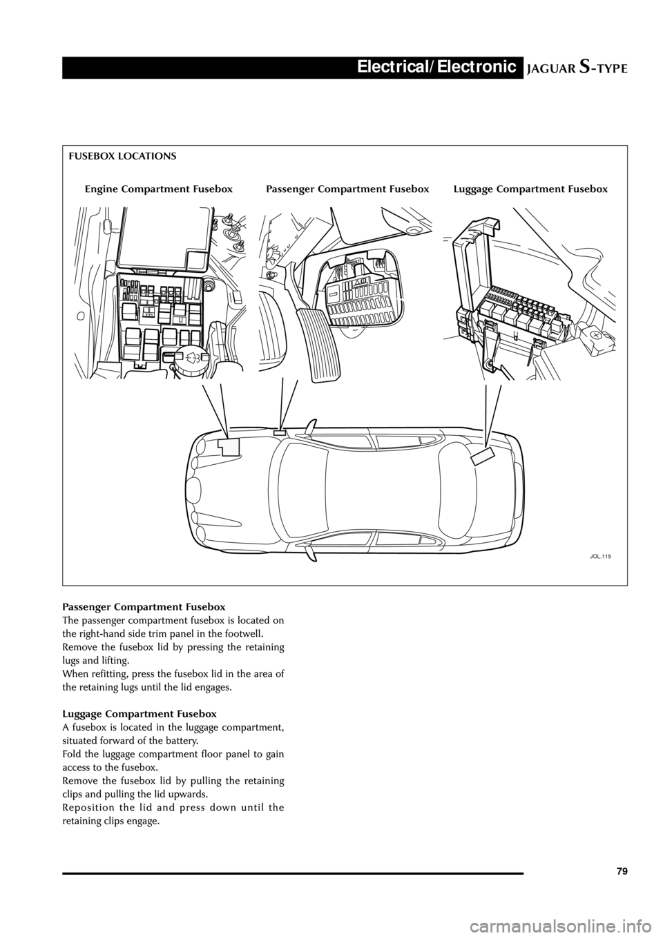
79 Passenger Compartment Fusebox
The passenger compartment fusebox is located on
the right-hand side trim panel in the footwell.
Remove the fusebox lid by pressing the retaining
lugs and lifting.
When refitting, press the fusebox lid in the area of
the retaining lugs until the lid engages.
Luggage Compartment Fusebox
A fusebox is located in the luggage compartment,
situated forward of the battery.
Fold the luggage compartment floor panel to gain
access to the fusebox.
Remove the fusebox lid by pulling the retaining
clips and pulling the lid upwards.
Reposition the lid and press down until the
retaining clips engage.
JOL.115
Engine Compartment FuseboxLuggage Compartment FuseboxPassenger Compartment Fusebox FUSEBOX LOCATIONS
Page 87 of 133

JAGUARS-TYPEElectrical/Electronic
82No Type Rating (amps) Colour Circuit
15 mini 5 Brown Adaptive damping module (ADRC)
16 mini 5 Brown Heated seat switch module,
electrochromic mirror, rain sensor
17 mini 5 Brown RCM, Generator warning lamp
18 mini 20 Yellow Radio, cellular phone, navigation unit
19 mini 15 Blue Steering column motors
20 mini 10 Red GECM, DATC, RECM, Instrument Pack,
brake shift interlock
21 mini 10 Red Power folding mirrors, electric sunblind
22 mini 10 Red DriverÕs door mirror, driverÕs door lock
motor
23 mini 10 Red Right-front high beam
24 mini 5 Brown Passive Anti-Theft System (PATS)
25 mini 10 Red Left-front low beam headlamp
26 - - - Not used
27 mini 10 Red Navigation display, radio, phone,
navigation module, Traffic Master
28 mini 5 Brown Battery-backed security sounder
29 mini 5 Brown Voice control, reversing aid, GECM,
Trailer tow ignition sense, VEMS
30 mini 5 Brown GECM
31 - - - Not used
32 mini 20 Yellow Accessory socket, cigar lighter
33 mini 10 Red GECM illumination power
34 - - - Not used
35 mini 5 Brown Stop lamp switch
Trunk Fusebox
No Type Rating (amps) Colour Circuit
1 mini 15 Blue Luggage compartment release solenoid
2 mini 10 Red Right rear direction indicators, back up,
fog lamps, side markers
3 mini 10 Red Left stop lamp
4 mini 10 Red Fuel door release solenoid
5 mini 10 Red Courtesy and map lamps
6 mini 10 Red Left rear direction indicators, back up,
fog lamps, side markers
7 mini 10 Red Right stop lamp
8 mini 10 Red Center high mounted stop lamp
9 mini 5 Brown Heated mirror
10 mini 5 Brown Traffic Master
11 mini 15 Blue Heated seats