fuel pump JAGUAR S TYPE 2005 1.G Technical Guide Update
[x] Cancel search | Manufacturer: JAGUAR, Model Year: 2005, Model line: S TYPE, Model: JAGUAR S TYPE 2005 1.GPages: 133, PDF Size: 3.48 MB
Page 43 of 133
JAGUARS-TYPEFuel System
38
Introduction
The fuel tank components, operation and layout
are new to Jaguar and have no commonality with
previous systems. The major features of the fuel
delivery system are the use of a saddle type tank
and a returnless fuel system. The evaporative loss
management system is similar in operation to that
fitted to the XJ and XK Series vehicles and on-
board refuelling vapour recovery (ORVR) is a
standard feature. For NAS markets only, leak test
diagnostics are performed.
Returnless Fuel System
The returnless fuel system delivers the correct
amount of fuel to the engine under all conditions
and at a constant pressure differential with
respect to manifold pressure. This is without the
need for a return line to the tank or a fuel rail
pressure regulator. The use of a return line and
the pressure drop across a regulator contribute to
vapour formation which can affect fuelling
calibration and requires a complex vapour
management system to meet legislative
requirements. Elimination of these components,
D.310.047
together with closed loop control of the variable
speed fuel pump, causes a reduction in the vapour
generated, lower fuel temperatures and better fuel
pressure control. Additional advantages include a
reduced load on the electrical system and
improved fuel economy.
Fuel Tank
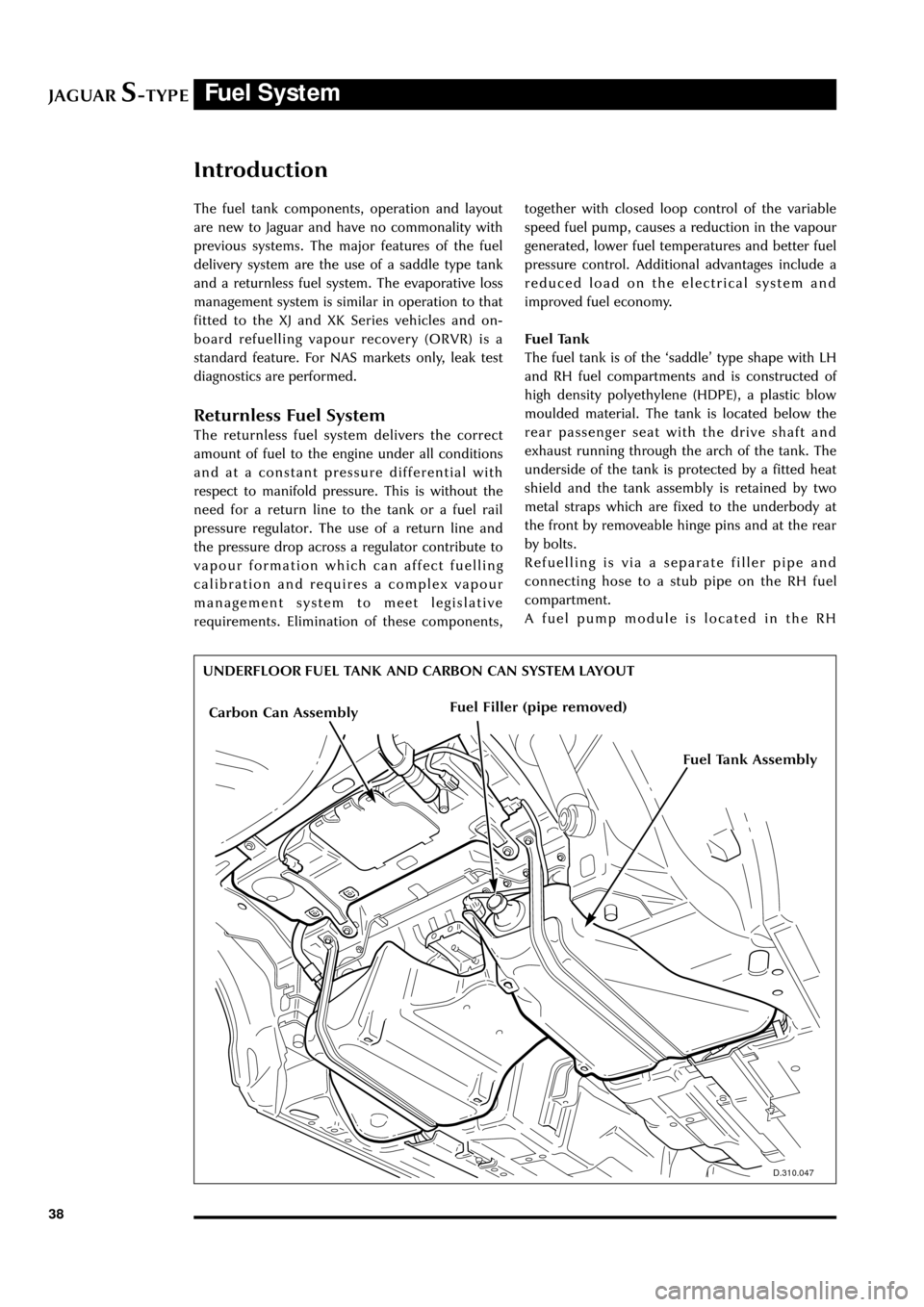
The fuel tank is of the ÔsaddleÕ type shape with LH
and RH fuel compartments and is constructed of
high density polyethylene (HDPE), a plastic blow
moulded material. The tank is located below the
rear passenger seat with the drive shaft and
exhaust running through the arch of the tank. The
underside of the tank is protected by a fitted heat
shield and the tank assembly is retained by two
metal straps which are fixed to the underbody at
the front by removeable hinge pins and at the rear
by bolts.
Refuelling is via a separate filler pipe and
connecting hose to a stub pipe on the RH fuel
compartment.
A fuel pump module is located in the RH
UNDERFLOOR FUEL TANK AND CARBON CAN SYSTEM LAYOUT
Carbon Can AssemblyFuel Filler (pipe removed)
Fuel Tank Assembly
Page 44 of 133
JAGUARS-TYPEFuel System
39
D.303.1242
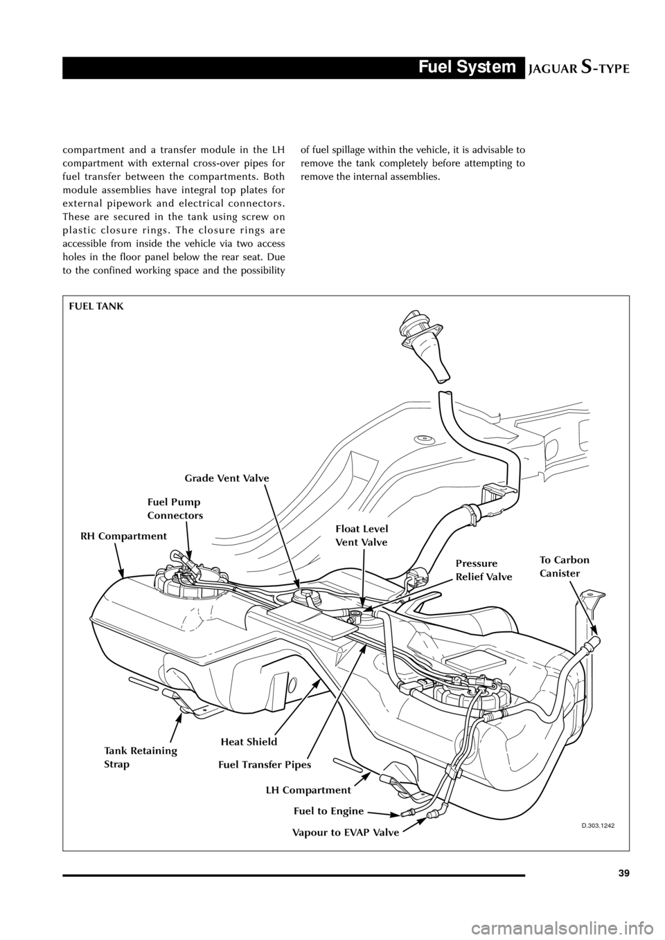
compartment and a transfer module in the LH
compartment with external cross-over pipes for
fuel transfer between the compartments. Both
module assemblies have integral top plates for
external pipework and electrical connectors.
These are secured in the tank using screw on
plastic closure rings. The closure rings are
accessible from inside the vehicle via two access
holes in the floor panel below the rear seat. Due
to the confined working space and the possibilityof fuel spillage within the vehicle, it is advisable to
remove the tank completely before attempting to
remove the internal assemblies.
FUEL TANK
Grade Vent Valve
Fuel Pump
Connectors
Pressure
Relief Valve
Float Level
Vent Valve
Heat Shield
To Carbon
Canister
Vapour to EVAP Valve
Fuel to Engine
Fuel Transfer Pipes
Tank Retaining
Strap
LH Compartment
RH Compartment
Page 45 of 133
JAGUARS-TYPEFuel System
40
J.310.046
Fuel Filter
Fuel Rail
Fuel Injectors
Fuel Injectors
Fuel Level
Senders
Jet PumpJet PumpFuel Pump
Fuel Reservoir
Parallel Pressure
Relief Valve
Pump and Sender
Electrical Connector
RH Compartment
LH Compartment
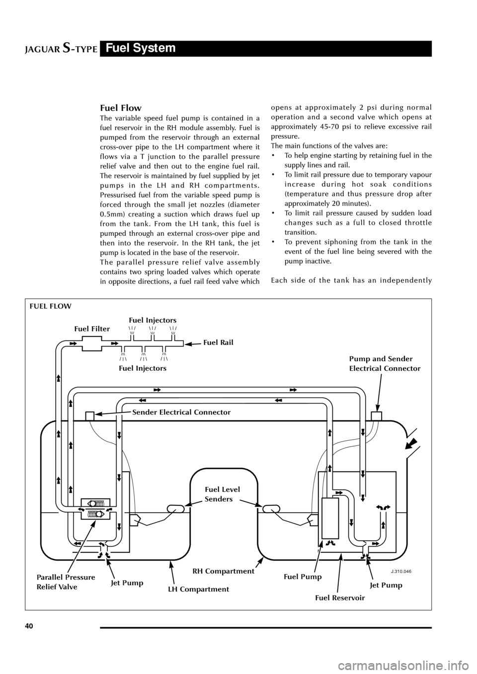
Fuel Flow
The variable speed fuel pump is contained in a
fuel reservoir in the RH module assembly. Fuel is
pumped from the reservoir through an external
cross-over pipe to the LH compartment where it
flows via a T junction to the parallel pressure
relief valve and then out to the engine fuel rail.
The reservoir is maintained by fuel supplied by jet
pumps in the LH and RH compartments.
Pressurised fuel from the variable speed pump is
forced through the small jet nozzles (diameter
0.5mm) creating a suction which draws fuel up
from the tank. From the LH tank, this fuel is
pumped through an external cross-over pipe and
then into the reservoir. In the RH tank, the jet
pump is located in the base of the reservoir.
The parallel pressure relief valve assembly
contains two spring loaded valves which operate
in opposite directions, a fuel rail feed valve whichopens at approximately 2 psi during normal
operation and a second valve which opens at
approximately 45-70 psi to relieve excessive rail
pressure.
The main functions of the valves are:
¥ To help engine starting by retaining fuel in the
supply lines and rail.
¥ To limit rail pressure due to temporary vapour
increase during hot soak conditions
(temperature and thus pressure drop after
approximately 20 minutes).
¥ To limit rail pressure caused by sudden load
changes such as a full to closed throttle
transition.
¥ To prevent siphoning from the tank in the
event of the fuel line being severed with the
pump inactive.
Each side of the tank has an independently
FUEL FLOW
Sender Electrical Connector
Page 46 of 133
JAGUARS-TYPEFuel System
41
JOL.062
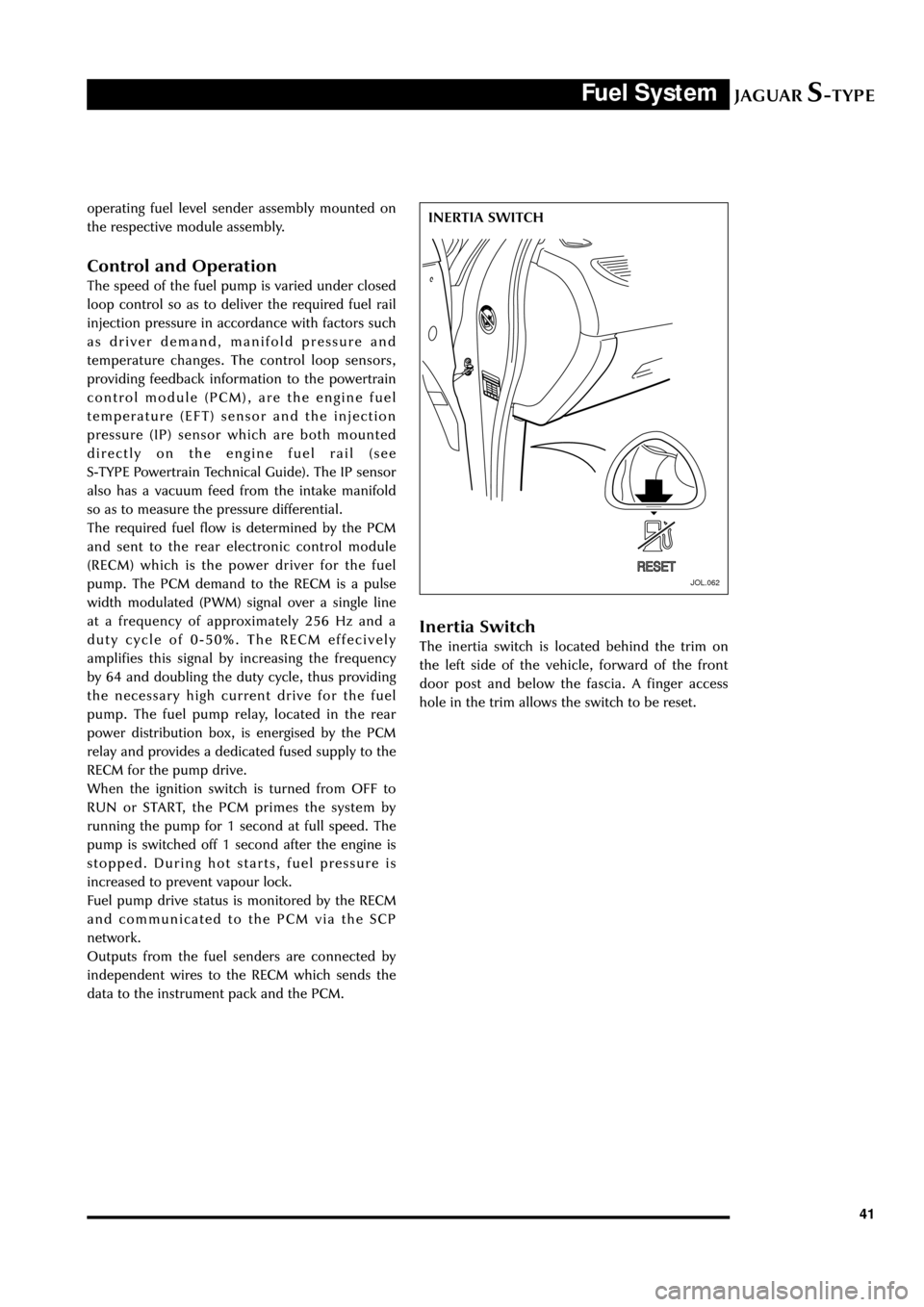
INERTIA SWITCH operating fuel level sender assembly mounted on
the respective module assembly.
Control and Operation
The speed of the fuel pump is varied under closed
loop control so as to deliver the required fuel rail
injection pressure in accordance with factors such
as driver demand, manifold pressure and
temperature changes. The control loop sensors,
providing feedback information to the powertrain
control module (PCM), are the engine fuel
temperature (EFT) sensor and the injection
pressure (IP) sensor which are both mounted
directly on the engine fuel rail (see
S-TYPE Powertrain Technical Guide). The IP sensor
also has a vacuum feed from the intake manifold
so as to measure the pressure differential.
The required fuel flow is determined by the PCM
and sent to the rear electronic control module
(RECM) which is the power driver for the fuel
pump. The PCM demand to the RECM is a pulse
width modulated (PWM) signal over a single line
at a frequency of approximately 256 Hz and a
duty cycle of 0-50%. The RECM effecively
amplifies this signal by increasing the frequency
by 64 and doubling the duty cycle, thus providing
the necessary high current drive for the fuel
pump. The fuel pump relay, located in the rear
power distribution box, is energised by the PCM
relay and provides a dedicated fused supply to the
RECM for the pump drive.
When the ignition switch is turned from OFF to
RUN or START, the PCM primes the system by
running the pump for 1 second at full speed. The
pump is switched off 1 second after the engine is
stopped. During hot starts, fuel pressure is
increased to prevent vapour lock.
Fuel pump drive status is monitored by the RECM
and communicated to the PCM via the SCP
network.
Outputs from the fuel senders are connected by
independent wires to the RECM which sends the
data to the instrument pack and the PCM.
Inertia Switch
The inertia switch is located behind the trim on
the left side of the vehicle, forward of the front
door post and below the fascia. A finger access
hole in the trim allows the switch to be reset.
Page 47 of 133
JAGUARS-TYPEFuel System
42
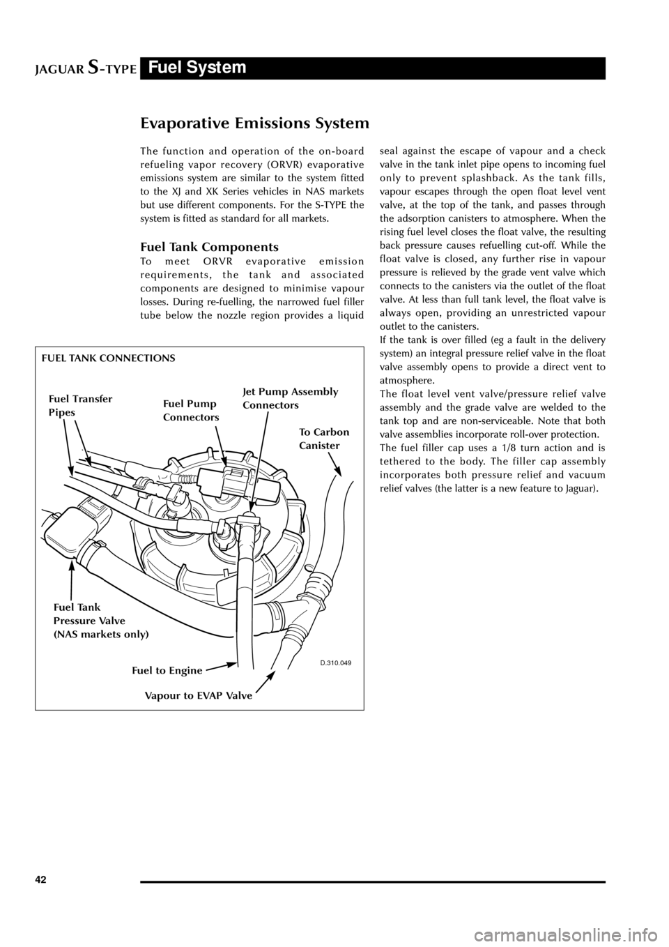
Evaporative Emissions System
The function and operation of the on-board
refueling vapor recovery (ORVR) evaporative
emissions system are similar to the system fitted
to the XJ and XK Series vehicles in NAS markets
but use different components. For the S-TYPE the
system is fitted as standard for all markets.
Fuel Tank Components
To meet ORVR evaporative emission
requirements, the tank and associated
components are designed to minimise vapour
losses. During re-fuelling, the narrowed fuel filler
tube below the nozzle region provides a liquidseal against the escape of vapour and a check
valve in the tank inlet pipe opens to incoming fuel
only to prevent splashback. As the tank fills,
vapour escapes through the open float level vent
valve, at the top of the tank, and passes through
the adsorption canisters to atmosphere. When the
rising fuel level closes the float valve, the resulting
back pressure causes refuelling cut-off. While the
float valve is closed, any further rise in vapour
pressure is relieved by the grade vent valve which
connects to the canisters via the outlet of the float
valve. At less than full tank level, the float valve is
always open, providing an unrestricted vapour
outlet to the canisters.
If the tank is over filled (eg a fault in the delivery
system) an integral pressure relief valve in the float
valve assembly opens to provide a direct vent to
atmosphere.
The float level vent valve/pressure relief valve
assembly and the grade valve are welded to the
tank top and are non-serviceable. Note that both
valve assemblies incorporate roll-over protection.
The fuel filler cap uses a 1/8 turn action and is
tethered to the body. The filler cap assembly
incorporates both pressure relief and vacuum
relief valves (the latter is a new feature to Jaguar).
D.310.049
FUEL TANK CONNECTIONS
Fuel Tank
Pressure Valve
(NAS markets only)
Jet Pump Assembly
Connectors
Fuel Pump
Connectors
To Carbon
Canister
Vapour to EVAP Valve
Fuel to Engine
Fuel Transfer
Pipes
Page 81 of 133
JAGUARS-TYPEElectrical/Electronic
76Air Conditioning Control Module (A/CCM)
The A/CCM is connected to the SCP
communication network. The A/CCM controls
automatic climate functions that maintain the
vehicle at a constant temperature setting.
Instrument Pack
The instrument pack is connected to the SCP
communication network. The instrument pack
displays information received on the SCP
including speedometer, odometer, fuel, and
message center warnings. The instrument pack
also controls the passive anti-theft system (PATS).
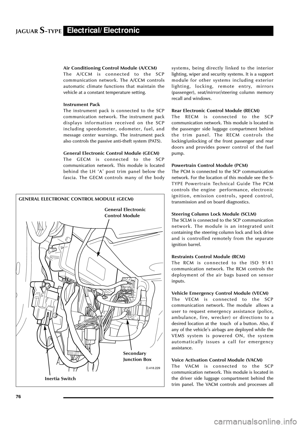
General Electronic Control Module (GECM)
The GECM is connected to the SCP
communication network. This module is located
behind the LH ÔAÕ post trim panel below the
fascia. The GECM controls many of the bodysystems, being directly linked to the interior
lighting, wiper and security systems. It is a support
module for other systems including exterior
lighting, locking, remote entry, mirrors
(passenger), seat/mirror/steering column memory
recall and windows.
Rear Electronic Control Module (RECM)
The RECM is connected to the SCP
communication network. This module is located in
the passenger side luggage compartment behind
the trim panel. The RECM controls the
locking/unlocking of the front passenger and rear
doors and provides power control of the fuel
pump.
Powertrain Control Module (PCM)
The PCM is connected to the SCP communication
network. For the location of this module see the S-
TYPE Powertrain Technical Guide The PCM
controls the engine performance, electronic
ignition, emission controls, speed control,
transmission and on board diagnostics.
Steering Column Lock Module (SCLM)
The SCLM is connected to the SCP communication
network. The module is an integrated unit
containing the steering column lock and lock drive
and is controlled remotely from the separate
ignition barrel.
Restraints Control Module (RCM)
The RCM is connected to the ISO 9141
communication network. The RCM controls the
deployment of the air bags based on sensor
inputs.
Vehicle Emergency Control Module (VECM)
The VECM is connected to the SCP
communication network. The module allows a
user to request emergency assistance (police,
ambulance, fire, wrecker) or directions to a
desired location at the touch of a button. Also, if
any of the vehicleÕs airbags are deployed while the
VEMS system is powered ON, the system
automatically issues a call for emergency
assistance.
Voice Activation Control Module (VACM)
The VACM is connected to the SCP
communication network. This module is located in
the driver side luggage compartment behind the
trim panel. The VACM controls and processes all
D.418.229
GENERAL ELECTRONIC CONTROL MODULE (GECM)
Inertia Switch
Secondary
Junction Box
General Electronic
Control Module
Page 85 of 133
JAGUARS-TYPEElectrical/Electronic
80
J.418.430
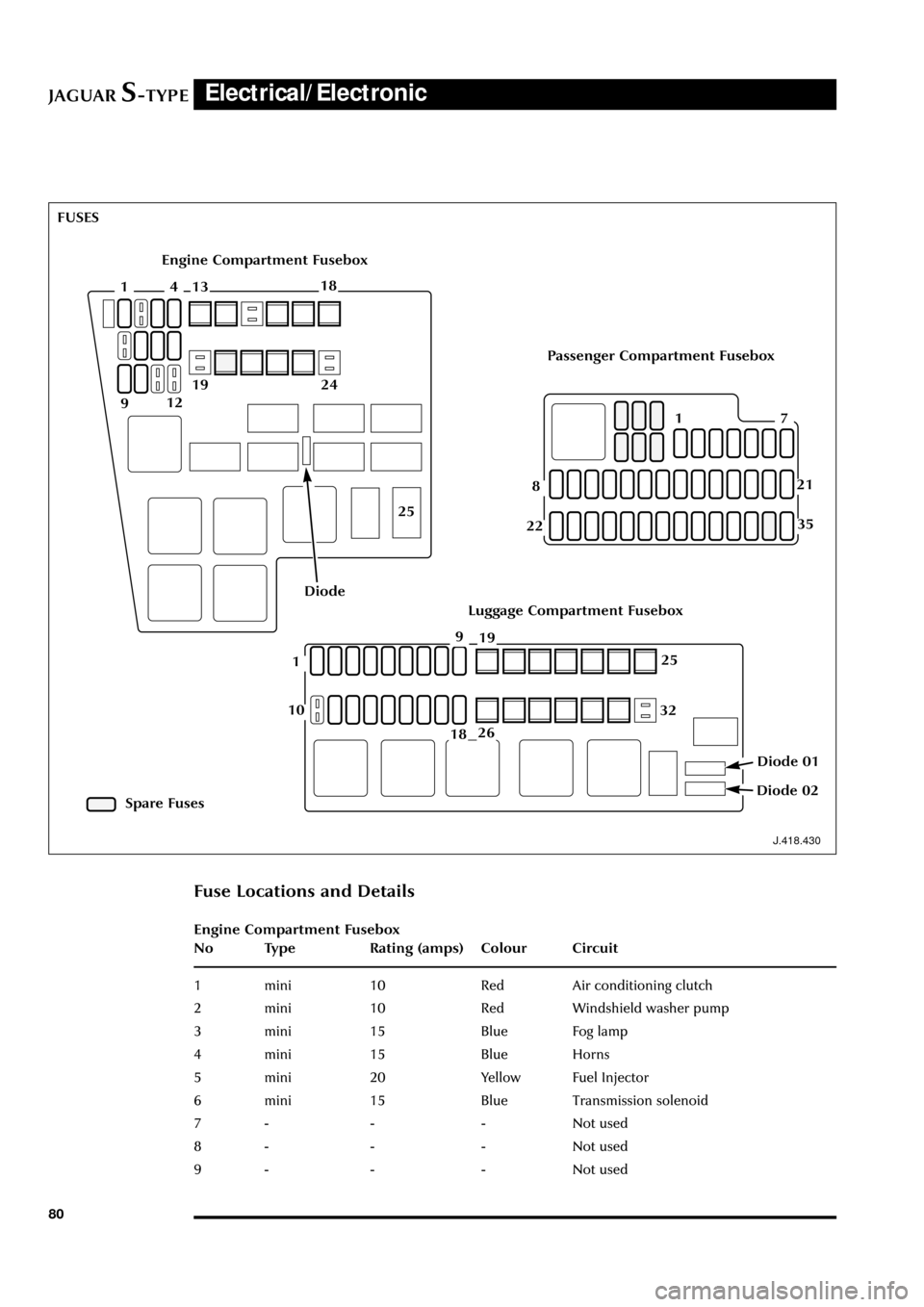
Fuse Locations and Details
Engine Compartment Fusebox
No Type Rating (amps) Colour Circuit
1 mini 10 Red Air conditioning clutch
2 mini 10 Red Windshield washer pump
3 mini 15 Blue Fog lamp
4 mini 15 Blue Horns
5 mini 20 Yellow Fuel Injector
6 mini 15 Blue Transmission solenoid
7 - - - Not used
8 - - - Not used
9 - - - Not used
Engine Compartment Fusebox
Luggage Compartment Fusebox
Passenger Compartment Fusebox
Spare Fuses FUSES
411318
912
2419
25
Diode
71
8
22
21
251
18
10
9
32
26
19
Diode 02
Diode 01
35
Page 86 of 133
JAGUARS-TYPEElectrical/Electronic
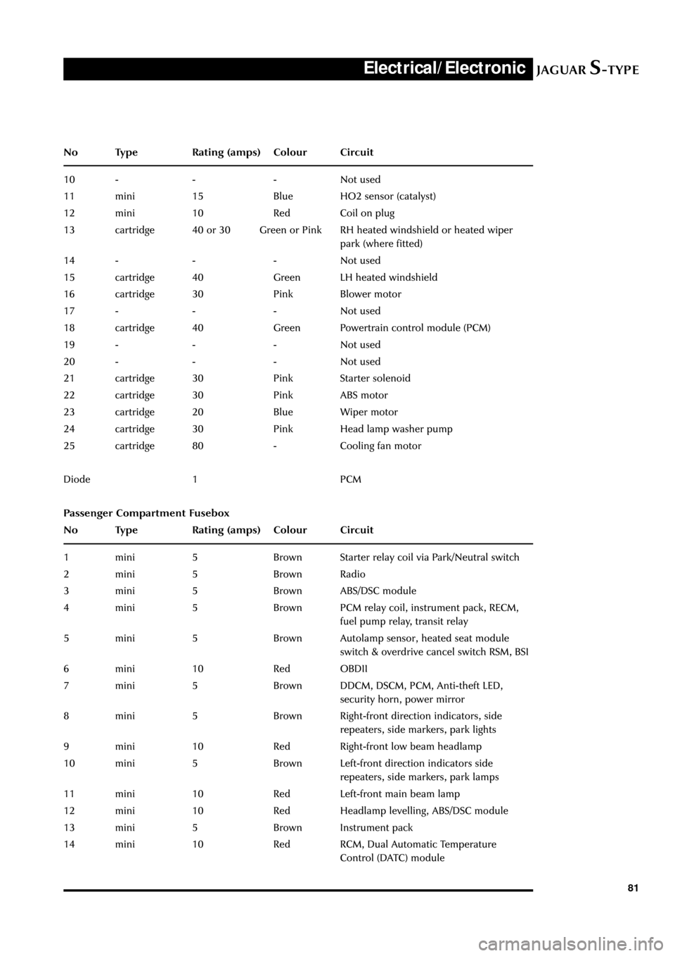
81 No Type Rating (amps) Colour Circuit
10 - - - Not used
11 mini 15 Blue HO2 sensor (catalyst)
12 mini 10 Red Coil on plug
13 cartridge 40 or 30 Green or Pink RH heated windshield or heated wiper
park (where fitted)
14 - - - Not used
15 cartridge 40 Green LH heated windshield
16 cartridge 30 Pink Blower motor
17 - - - Not used
18 cartridge 40 Green Powertrain control module (PCM)
19 - - - Not used
20 - - - Not used
21 cartridge 30 Pink Starter solenoid
22 cartridge 30 Pink ABS motor
23 cartridge 20 Blue Wiper motor
24 cartridge 30 Pink Head lamp washer pump
25 cartridge 80 - Cooling fan motor
Diode 1 PCM
Passenger Compartment Fusebox
No Type Rating (amps) Colour Circuit
1 mini 5 Brown Starter relay coil via Park/Neutral switch
2 mini 5 Brown Radio
3 mini 5 Brown ABS/DSC module
4 mini 5 Brown PCM relay coil, instrument pack, RECM,
fuel pump relay, transit relay
5 mini 5 Brown Autolamp sensor, heated seat module
switch & overdrive cancel switch RSM, BSI
6 mini 10 Red OBDII
7 mini 5 Brown DDCM, DSCM, PCM, Anti-theft LED,
security horn, power mirror
8 mini 5 Brown Right-front direction indicators, side
repeaters, side markers, park lights
9 mini 10 Red Right-front low beam headlamp
10 mini 5 Brown Left-front direction indicators side
repeaters, side markers, park lamps
11 mini 10 Red Left-front main beam lamp
12 mini 10 Red Headlamp levelling, ABS/DSC module
13 mini 5 Brown Instrument pack
14 mini 10 Red RCM, Dual Automatic Temperature
Control (DATC) module
Page 88 of 133
JAGUARS-TYPEElectrical/Electronic
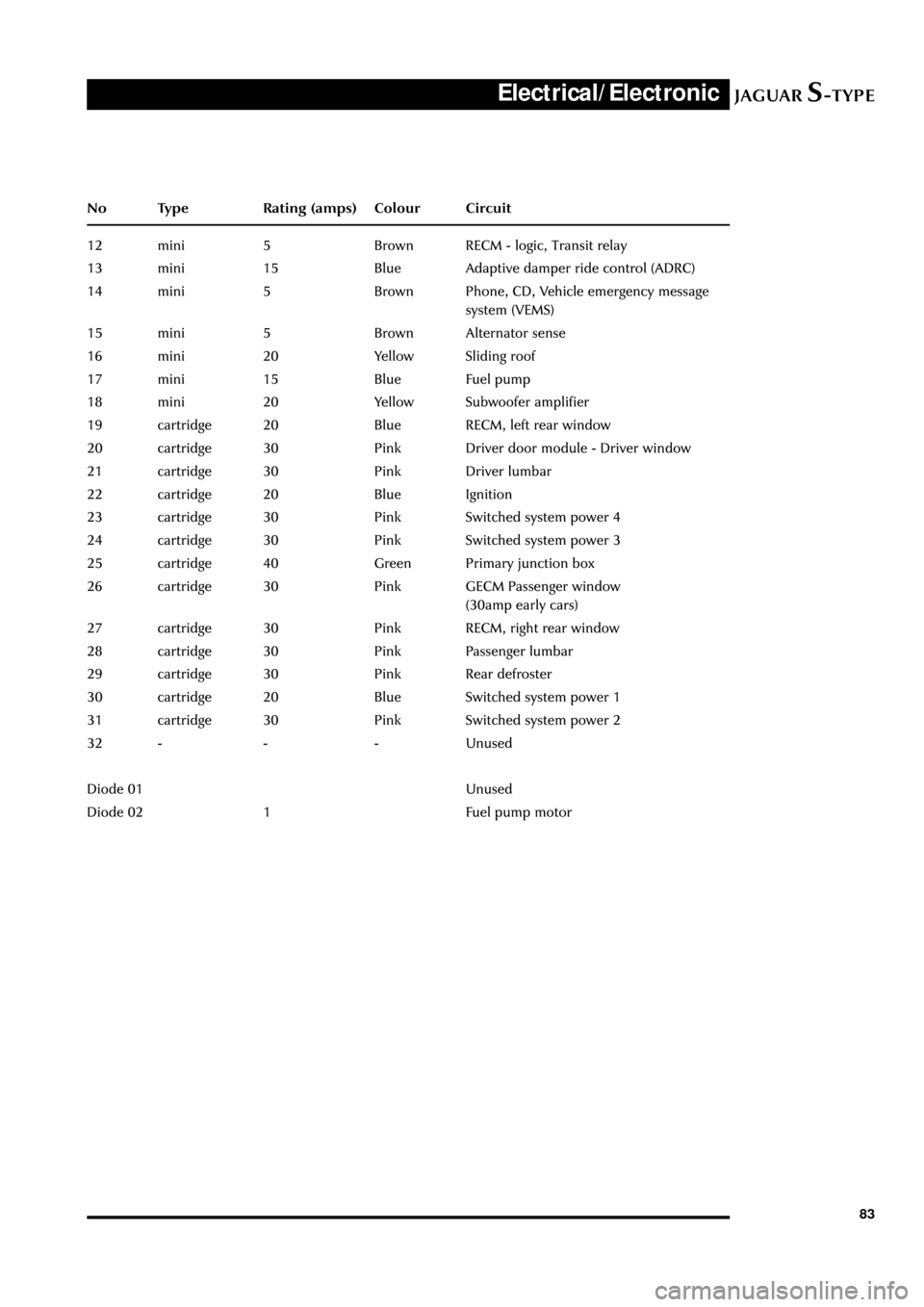
83 No Type Rating (amps) Colour Circuit
12 mini 5 Brown RECM - logic, Transit relay
13 mini 15 Blue Adaptive damper ride control (ADRC)
14 mini 5 Brown Phone, CD, Vehicle emergency message
system (VEMS)
15 mini 5 Brown Alternator sense
16 mini 20 Yellow Sliding roof
17 mini 15 Blue Fuel pump
18 mini 20 Yellow Subwoofer amplifier
19 cartridge 20 Blue RECM, left rear window
20 cartridge 30 Pink Driver door module - Driver window
21 cartridge 30 Pink Driver lumbar
22 cartridge 20 Blue Ignition
23 cartridge 30 Pink Switched system power 4
24 cartridge 30 Pink Switched system power 3
25 cartridge 40 Green Primary junction box
26 cartridge 30 Pink GECM Passenger window
(30amp early cars)
27 cartridge 30 Pink RECM, right rear window
28 cartridge 30 Pink Passenger lumbar
29 cartridge 30 Pink Rear defroster
30 cartridge 20 Blue Switched system power 1
31 cartridge 30 Pink Switched system power 2
32 - - - Unused
Diode 01 Unused
Diode 02 1 Fuel pump motor
Page 90 of 133
JAGUARS-TYPEElectrical/Electronic
85 5. Switched system power 4 relay
6. Fuel pump relay
7. Brake shift interlock relay
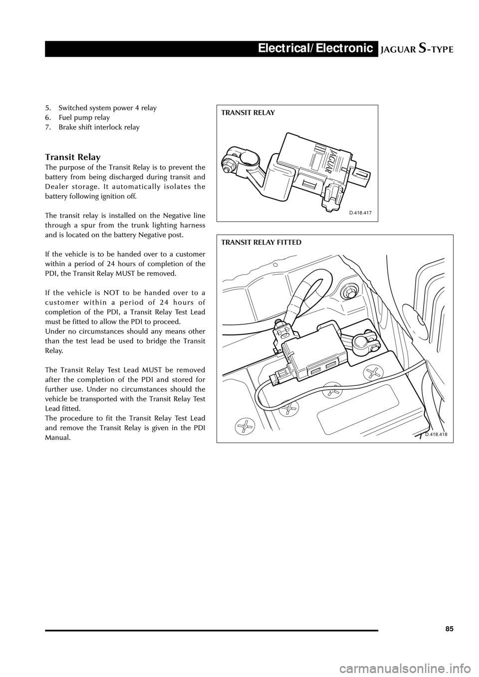
Transit Relay
The purpose of the Transit Relay is to prevent the
battery from being discharged during transit and
Dealer storage. It automatically isolates the
battery following ignition off.
The transit relay is installed on the Negative line
through a spur from the trunk lighting harness
and is located on the battery Negative post.
If the vehicle is to be handed over to a customer
within a period of 24 hours of completion of the
PDI, the Transit Relay MUST be removed.
If the vehicle is NOT to be handed over to a
customer within a period of 24 hours of
completion of the PDI, a Transit Relay Test Lead
must be fitted to allow the PDI to proceed.
Under no circumstances should any means other
than the test lead be used to bridge the Transit
Relay.
The Transit Relay Test Lead MUST be removed
after the completion of the PDI and stored for
further use. Under no circumstances should the
vehicle be transported with the Transit Relay Test
Lead fitted.
The procedure to fit the Transit Relay Test Lead
and remove the Transit Relay is given in the PDI
Manual.
D.418.417
D.418.418
TRANSIT RELAY
TRANSIT RELAY FITTED