cooling JAGUAR S TYPE 2005 1.G Technical Guide Update
[x] Cancel search | Manufacturer: JAGUAR, Model Year: 2005, Model line: S TYPE, Model: JAGUAR S TYPE 2005 1.GPages: 133, PDF Size: 3.48 MB
Page 18 of 133

JAGUARS-TYPEBody
13
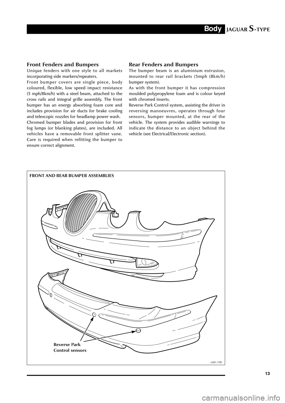
Front Fenders and Bumpers
Unique fenders with one style to all markets
incorporating side markers/repeaters.
Front bumper covers are single piece, body
coloured, flexible, low speed impact resistance
(5 mph/8km/h) with a steel beam, attached to the
cross rails and integral grille assembly. The front
bumper has an energy absorbing foam core and
includes provision for air ducts for brake cooling
and telescopic nozzles for headlamp power wash.
Chromed bumper blades and provision for front
fog lamps (or blanking plates), are included. All
vehicles have a removable front splitter vane.
Care is required when refitting the bumper to
ensure correct alignment.
Rear Fenders and Bumpers
The bumper beam is an aluminium extrusion,
mounted to rear rail brackets (5mph (8km/h)
bumper system).
As with the front bumper it has compression
moulded polypropylene foam and is colour keyed
with chromed inserts.
Reverse Park Control system, assisting the driver in
reversing manoeuvres, operates through four
sensors, bumper mounted, at the rear of the
vehicle. The system provides audible warnings to
indicate the distance to an object behind the
vehicle (see Electrical/Electronic section).
FRONT AND REAR BUMPER ASSEMBLIES
J.501.1781
Reverse Park
Control sensors
Page 52 of 133

JAGUARS-TYPEChassis
47
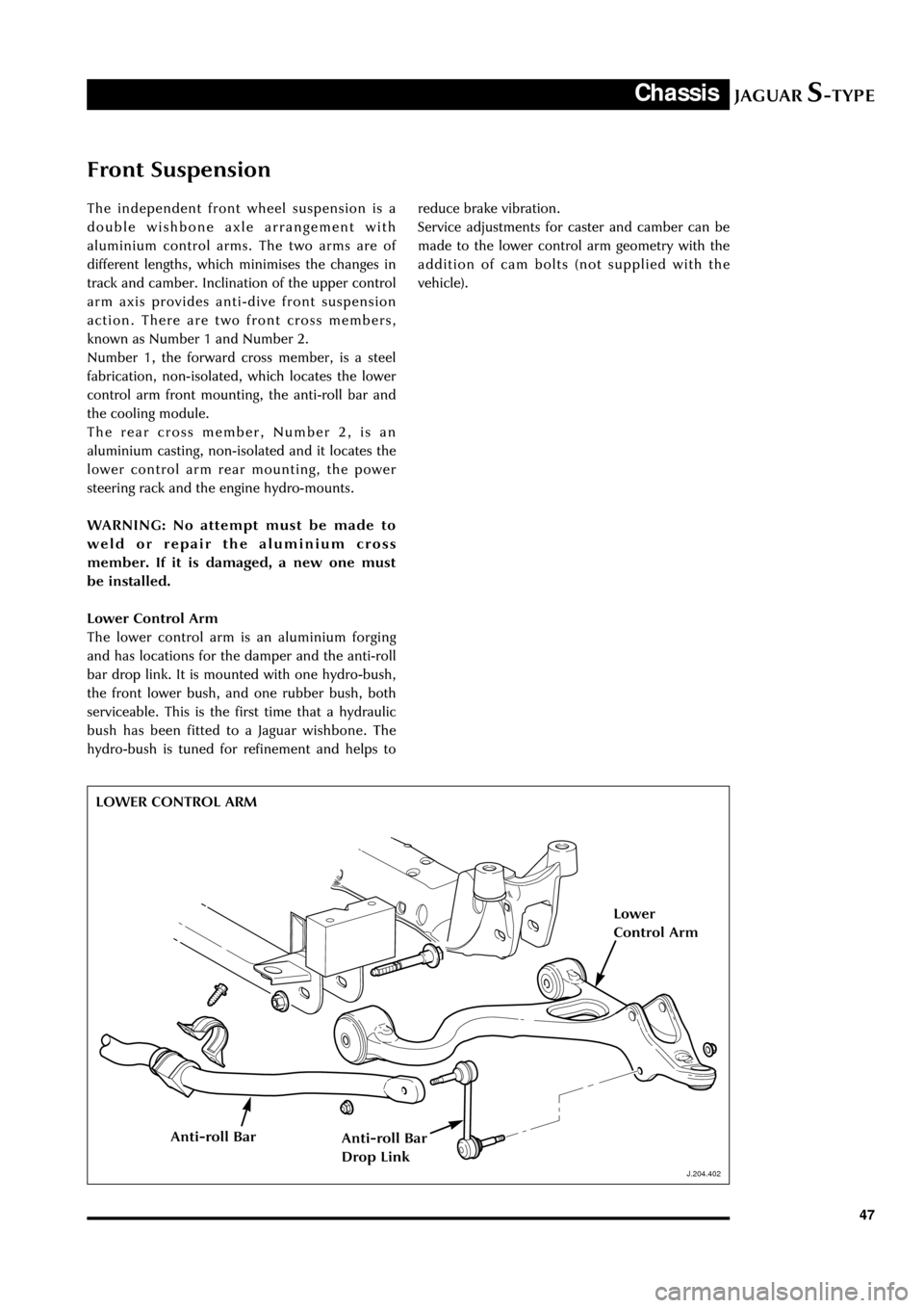
Front Suspension
The independent front wheel suspension is a
double wishbone axle arrangement with
aluminium control arms. The two arms are of
different lengths, which minimises the changes in
track and camber. Inclination of the upper control
arm axis provides anti-dive front suspension
action. There are two front cross members,
known as Number 1 and Number 2.
Number 1, the forward cross member, is a steel
fabrication, non-isolated, which locates the lower
control arm front mounting, the anti-roll bar and
the cooling module.
The rear cross member, Number 2, is an
aluminium casting, non-isolated and it locates the
lower control arm rear mounting, the power
steering rack and the engine hydro-mounts.
WARNING: No attempt must be made to
weld or repair the aluminium cross
member. If it is damaged, a new one must
be installed.
Lower Control Arm
The lower control arm is an aluminium forging
and has locations for the damper and the anti-roll
bar drop link. It is mounted with one hydro-bush,
the front lower bush, and one rubber bush, both
serviceable. This is the first time that a hydraulic
bush has been fitted to a Jaguar wishbone. The
hydro-bush is tuned for refinement and helps to
J.204.402
reduce brake vibration.
Service adjustments for caster and camber can be
made to the lower control arm geometry with the
addition of cam bolts (not supplied with the
vehicle).
LOWER CONTROL ARM
J.204.402
Lower
Control Arm
Anti-roll BarAnti-roll Bar
Drop Link
Page 68 of 133

JAGUARS-TYPEClimate Control
63
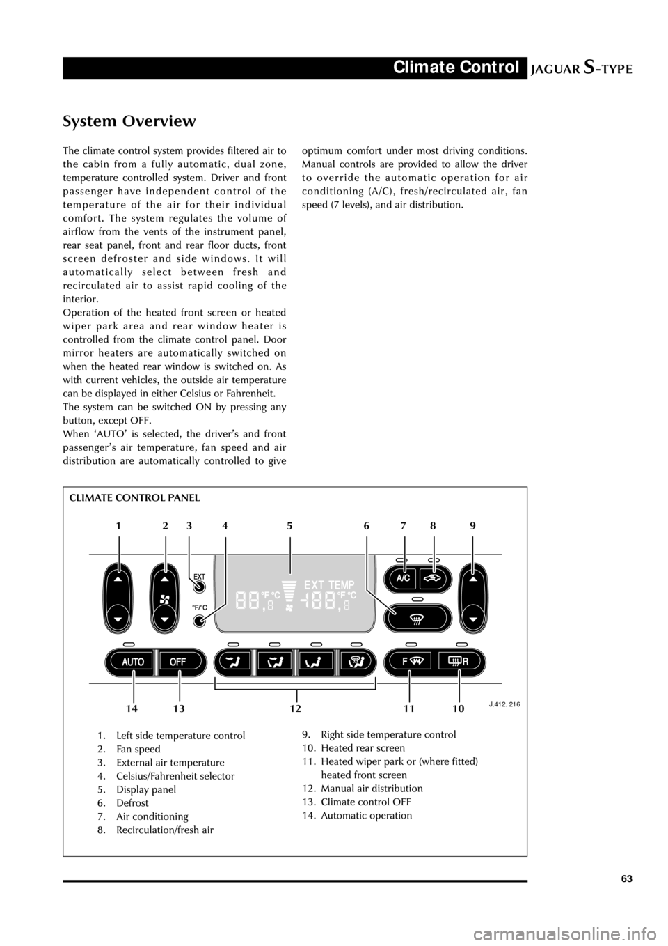
System Overview
The climate control system provides filtered air to
the cabin from a fully automatic, dual zone,
temperature controlled system. Driver and front
passenger have independent control of the
temperature of the air for their individual
comfort. The system regulates the volume of
airflow from the vents of the instrument panel,
rear seat panel, front and rear floor ducts, front
screen defroster and side windows. It will
automatically select between fresh and
recirculated air to assist rapid cooling of the
interior.
Operation of the heated front screen or heated
wiper park area and rear window heater is
controlled from the climate control panel. Door
mirror heaters are automatically switched on
when the heated rear window is switched on. As
with current vehicles, the outside air temperature
can be displayed in either Celsius or Fahrenheit.
The system can be switched ON by pressing any
button, except OFF.
When ÔAUTOÕ is selected, the driverÕs and front
passengerÕs air temperature, fan speed and air
distribution are automatically controlled to give
J.412. 216
1. Left side temperature control
2. Fan speed
3. External air temperature
4. Celsius/Fahrenheit selector
5. Display panel
6. Defrost
7. Air conditioning
8. Recirculation/fresh air9. Right side temperature control
10. Heated rear screen
11. Heated wiper park or (where fitted)
heated front screen
12. Manual air distribution
13. Climate control OFF
14. Automatic operation optimum comfort under most driving conditions.
Manual controls are provided to allow the driver
to override the automatic operation for air
conditioning (A/C), fresh/recirculated air, fan
speed (7 levels), and air distribution.
12 65 4 3
109 8 7
11 13 12 14 CLIMATE CONTROL PANEL
Page 69 of 133

JAGUARS-TYPEClimate Control
64Control Panel
The control panel is a combined unit
incorporating the air conditioning control module
(A/CCM).
Heater/Evaporator and Blower
A single blower, heater and evaporator are fitted
to the passenger side of the vehicle behind the
fascia. Air intake is from the passenger side via
leaf screen slots (see page 16). A particle filter is
mounted forward of the bulkhead in a rain/water
collector box. Mounting of the heater/evaporator
unit and blower assembly is by three bulkhead
fixings and one locator pin.
Condensate drainage is integral with the
heater/evaporator unit and therefore has no
separate drain tubes. The heater matrix is a dual
heater unit with three heater pipes, two inlets of
16mm diameter and one outlet of 19mm
diameter.
D.412.217
Underbonnet Components
Both V6 and V8 engine configurations include a
water valve controlled heating (dual) system and
the valve is mounted behind the right-hand side
headlamp. The V8 engine system, as with current
cars, has a water pump to supplement idle water
flow through the heater and this is mounted on
the right-hand side of the cooling pack. The pump
is held in a mounting rubber, which is pushed
over two pillars on the rear of the fan shroud and
held with two screws.
Condenser
The black-painted aluminium condenser is located
to the front of the combi-cooler and mounts to its
end tanks. The condenser end tubes push into two
grommets, which are in turn held in two steel
brackets, screwed to the radiator end tanks. The
bottom of the condenser is screwed directly into
the radiator tanks. A radiator cooling duct clips
onto the condenser end tanks and also pushes
onto the lower radiator channel. The duct ensures
that all available airflow is directed through the
cooling module.
HEATER/EVAPORATOR AND BLOWER
Blower
Heater/Evaporator
Page 72 of 133

JAGUARS-TYPEClimate Control
67 Pipework
The suction hose and liquid line are a one-piece
assembly. A single screw connects them to the air
conditioning unit manifold at the bulkhead. A
further screw fixing and push-in clip secures them
at the side of the engine bay. The liquid line fixed
to the cooling module then joins with a block
fitting and the suction hose connects with a quick
connect fitting and routes across the underneath
of the cooling module to the compressor. The
compressor suction and discharge hoses are also a
one piece assembly.
A pressure transducer is fitted to the discharge
hose as it connects to the rear of the condenser.
The high side charge port is situated on the
manifold connecting to the receiver drier whilst
the low side is adjacent to the compressor behind
the LH front wheel.
The compressor is a 9Occ scroll, which is variable
from 100% to 30%. Compressor is standard
specification to all vehicles although package
makes them unique to V6 and V8.
Air Distribution
Air distribution is as follows:
¥ Defrost duct integral with the fascia.
¥ Face vents, plenum, manifold, centre face
duct, side face duct, side window demist duct
are all sub-assembled into the fascia.
¥ Driver and front seat passenger foot ducts are
installed in the fascia after it has been fitted
to the vehicle.
¥ Rear foot ducts are fitted to the underframe.
¥ Rear face duct fitted to transmission tunnel.
¥ Rear face vent fitted to console.
¥ Extractor boxes fitted in rear quarter panels.
All flaps are electric servo controlled and
comprise:
¥ Fresh/recirculation - heater/evaporator unit.
¥ Cold air bypass - heater/evaporator unit.
¥ Foot flap - mounted on plenum.
¥ Defrost flap - mounted on plenum.
¥ Face flap - mounted on plenum.
Sensors, for operation of the system, are:
¥ Ambient temperature sensor - located behind
the lower front grille.
¥ Solar sensor - fitted to the top centre of the
fascia at the defrost grille
¥ In-car sensor - aspirated from the plenum
venturi sensor mounted inboard of the
steering column.¥ Two heater air outlet sensors
¥ One evaporator air outlet sensor
Servicing
Routine servicing consists of particle filter
replacement.
Replaceable items on the climate control system
are:
¥ Servo complete with linkages
¥ Sensors
¥ Evaporator and seals
¥ Heater core and seals
¥ Blower motor
¥ Impeller/blower motor wheel
¥ Hoses
¥ Registers/vents
¥ Ducts, except the defrost
¥ Defrost and side window demist grilles
¥ Control unit
¥ Compressor
¥ Water pump
¥ Water valve
¥ Receiver/drier
¥ Condenser
There are no panel diagnostics but PDU facility is
available with extensive capability, similar to
current XJ and XK Series.
System refrigerant is R134a. Vehicle charge weight
is 800 gms and charging is through the high side
charge port only.
Oil type is WSH-MIC231-B and refill quantity is
180 cc -220 cc.
Special tools are hose clamp pliers and air-
conditioning hoses spring lock de-coupler.
General information
Ensure that the grille at the base of the windshield
is kept clear of leaves, snow or other obstructions.
A solar sensor is mounted on top of the fascia, in
the centre of the defrost grille, and this should not
be covered.
The air conditioning system should be run briefly
at least once each week with a cold setting to
prevent the seals from drying out with subsequent
refrigerant leaks.
When the engine and vehicle interior are cold the
fan speed may be low until the engine has warmed
up, this avoids excessively cold air being blown
into the cabin.
Page 86 of 133

JAGUARS-TYPEElectrical/Electronic
81 No Type Rating (amps) Colour Circuit
10 - - - Not used
11 mini 15 Blue HO2 sensor (catalyst)
12 mini 10 Red Coil on plug
13 cartridge 40 or 30 Green or Pink RH heated windshield or heated wiper
park (where fitted)
14 - - - Not used
15 cartridge 40 Green LH heated windshield
16 cartridge 30 Pink Blower motor
17 - - - Not used
18 cartridge 40 Green Powertrain control module (PCM)
19 - - - Not used
20 - - - Not used
21 cartridge 30 Pink Starter solenoid
22 cartridge 30 Pink ABS motor
23 cartridge 20 Blue Wiper motor
24 cartridge 30 Pink Head lamp washer pump
25 cartridge 80 - Cooling fan motor
Diode 1 PCM
Passenger Compartment Fusebox
No Type Rating (amps) Colour Circuit
1 mini 5 Brown Starter relay coil via Park/Neutral switch
2 mini 5 Brown Radio
3 mini 5 Brown ABS/DSC module
4 mini 5 Brown PCM relay coil, instrument pack, RECM,
fuel pump relay, transit relay
5 mini 5 Brown Autolamp sensor, heated seat module
switch & overdrive cancel switch RSM, BSI
6 mini 10 Red OBDII
7 mini 5 Brown DDCM, DSCM, PCM, Anti-theft LED,
security horn, power mirror
8 mini 5 Brown Right-front direction indicators, side
repeaters, side markers, park lights
9 mini 10 Red Right-front low beam headlamp
10 mini 5 Brown Left-front direction indicators side
repeaters, side markers, park lamps
11 mini 10 Red Left-front main beam lamp
12 mini 10 Red Headlamp levelling, ABS/DSC module
13 mini 5 Brown Instrument pack
14 mini 10 Red RCM, Dual Automatic Temperature
Control (DATC) module
Page 101 of 133

JAGUARS-TYPEElectrical/Electronic
96
JOL.002
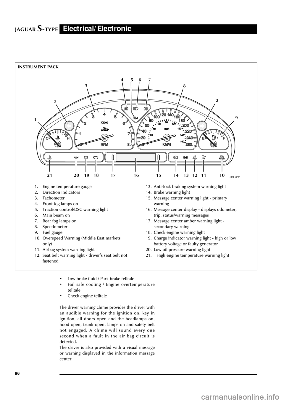
1. Engine temperature gauge
2. Direction indicators
3. Tachometer
4. Front fog lamps on
5. Traction control/DSC warning light
6. Main beam on
7. Rear fog lamps on
8. Speedometer
9. Fuel gauge
10. Overspeed Warning (Middle East markets
only)
11. Airbag system warning light
12. Seat belt warning light - driverÕs seat belt not
fastened13. Anti-lock braking system warning light
14. Brake warning light
15. Message center warning light - primary
warning
16. Message center display - displays odometer,
trip, status/warning messages
17. Message center amber warning light -
secondary warning
18. Check engine warning light
19. Charge indicator warning light - high or low
battery voltage or faulty generator
20. Low oil pressure warning light
21. High engine temperature warning light INSTRUMENT PACK
126 5 4
3
109 8 7
112
13 12 18 20 19 1416 15 17 21
¥ Low brake fluid / Park brake telltale
¥ Fail safe cooling / Engine overtemperature
telltale
¥ Check engine telltale
The driver warning chime provides the driver with
an audible warning for the ignition on, key in
ignition, all doors open and the headlamps on,
hood open, trunk open, lamps on and safety belt
not engaged. A chime will sound every one
second when a fault in the air bag circuit is
detected.
The driver is also provided with a visual message
or warning displayed in the information message
center.