four wheel drive JAGUAR S TYPE 2005 1.G Technical Guide Update
[x] Cancel search | Manufacturer: JAGUAR, Model Year: 2005, Model line: S TYPE, Model: JAGUAR S TYPE 2005 1.GPages: 133, PDF Size: 3.48 MB
Page 17 of 133
JAGUARS-TYPEBody
12
Front and Centre Floor Pan
The floor pan is a three-piece construction with
handed dash panels, welded front suspension
housing, an integral centre bearing panel for the
driveshaft and a large under-tunnel heatshield.
Rear Floor Pan
Multi-piece floor pan design, the rear tub is
designed to accept either a full size or space saver
spare wheel and the luggage compartment has
four tie-down luggage loops. Two plastic covers
are located under the rear seat and these give
easy access to the fuel tank mounted components.
A plastic battery tray is located below the luggage
load floor.
Roof
Provision has been made for roof rack fixings and
the roof has reinforcement for vehicles fitted with
a the sliding roof.
Sliding Roof
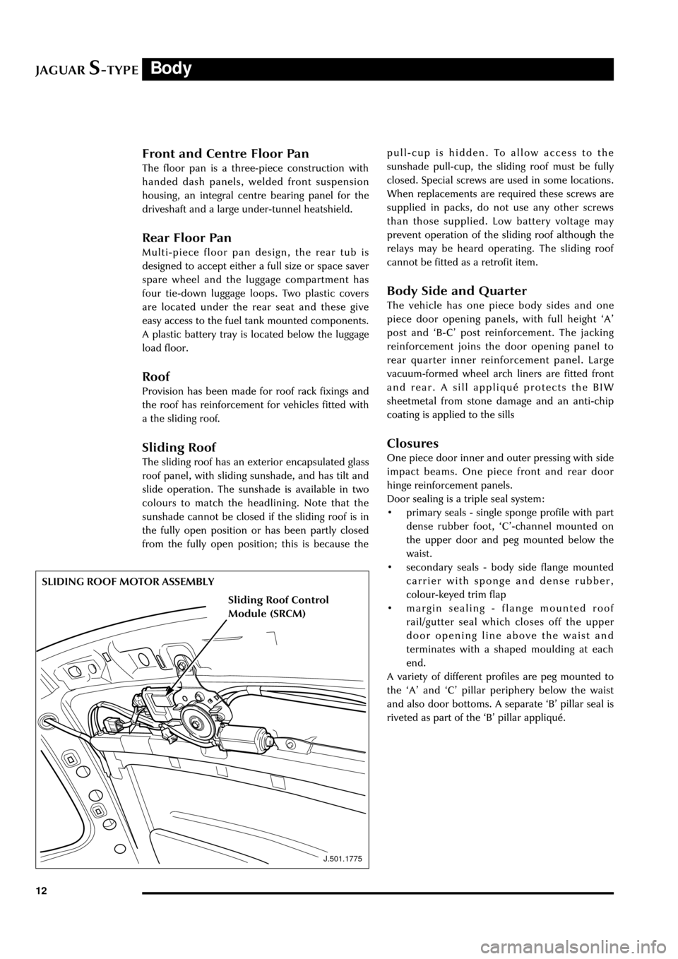
The sliding roof has an exterior encapsulated glass
roof panel, with sliding sunshade, and has tilt and
slide operation. The sunshade is available in two
colours to match the headlining. Note that the
sunshade cannot be closed if the sliding roof is in
the fully open position or has been partly closed
from the fully open position; this is because the
J.501.1775
SLIDING ROOF MOTOR ASSEMBLYpull-cup is hidden. To allow access to the
sunshade pull-cup, the sliding roof must be fully
closed. Special screws are used in some locations.
When replacements are required these screws are
supplied in packs, do not use any other screws
than those supplied. Low battery voltage may
prevent operation of the sliding roof although the
relays may be heard operating. The sliding roof
cannot be fitted as a retrofit item.
Body Side and Quarter
The vehicle has one piece body sides and one
piece door opening panels, with full height ÔAÕ
post and ÔB-CÕ post reinforcement. The jacking
reinforcement joins the door opening panel to
rear quarter inner reinforcement panel. Large
vacuum-formed wheel arch liners are fitted front
and rear. A sill appliquŽ protects the BIW
sheetmetal from stone damage and an anti-chip
coating is applied to the sills
Closures
One piece door inner and outer pressing with side
impact beams. One piece front and rear door
hinge reinforcement panels.
Door sealing is a triple seal system:
¥ primary seals - single sponge profile with part
dense rubber foot, ÔCÕ-channel mounted on
the upper door and peg mounted below the
waist.
¥ secondary seals - body side flange mounted
carrier with sponge and dense rubber,
colour-keyed trim flap
¥ margin sealing - flange mounted roof
rail/gutter seal which closes off the upper
door opening line above the waist and
terminates with a shaped moulding at each
end.
A variety of different profiles are peg mounted to
the ÔAÕ and ÔCÕ pillar periphery below the waist
and also door bottoms. A separate ÔBÕ pillar seal is
riveted as part of the ÔBÕ pillar appliquŽ.
Sliding Roof Control
Module (SRCM)
Page 61 of 133
JAGUARS-TYPEChassis
56
D.206.177
current vehicles and the 12 valve unit has a 47-
way connector with lever cam. DSC calculates the
real vehicle motion (forward and gearing) and
compares it to the direction initially chosen by the
driver. A steering rate sensor is located on the
steering column and is used to calculate steering
angle. A yaw rate sensor and lateral accelerometer
are located on a bracket behind the hand brake
lever and are used to calculate the vehicle under
or over steer and any side slip.
As soon as DSC recognises that the driver is not
reacting sufficiently to compensate a deviation,
DSC intervenes by applying brake force to each of
the four wheels individually to control yaw
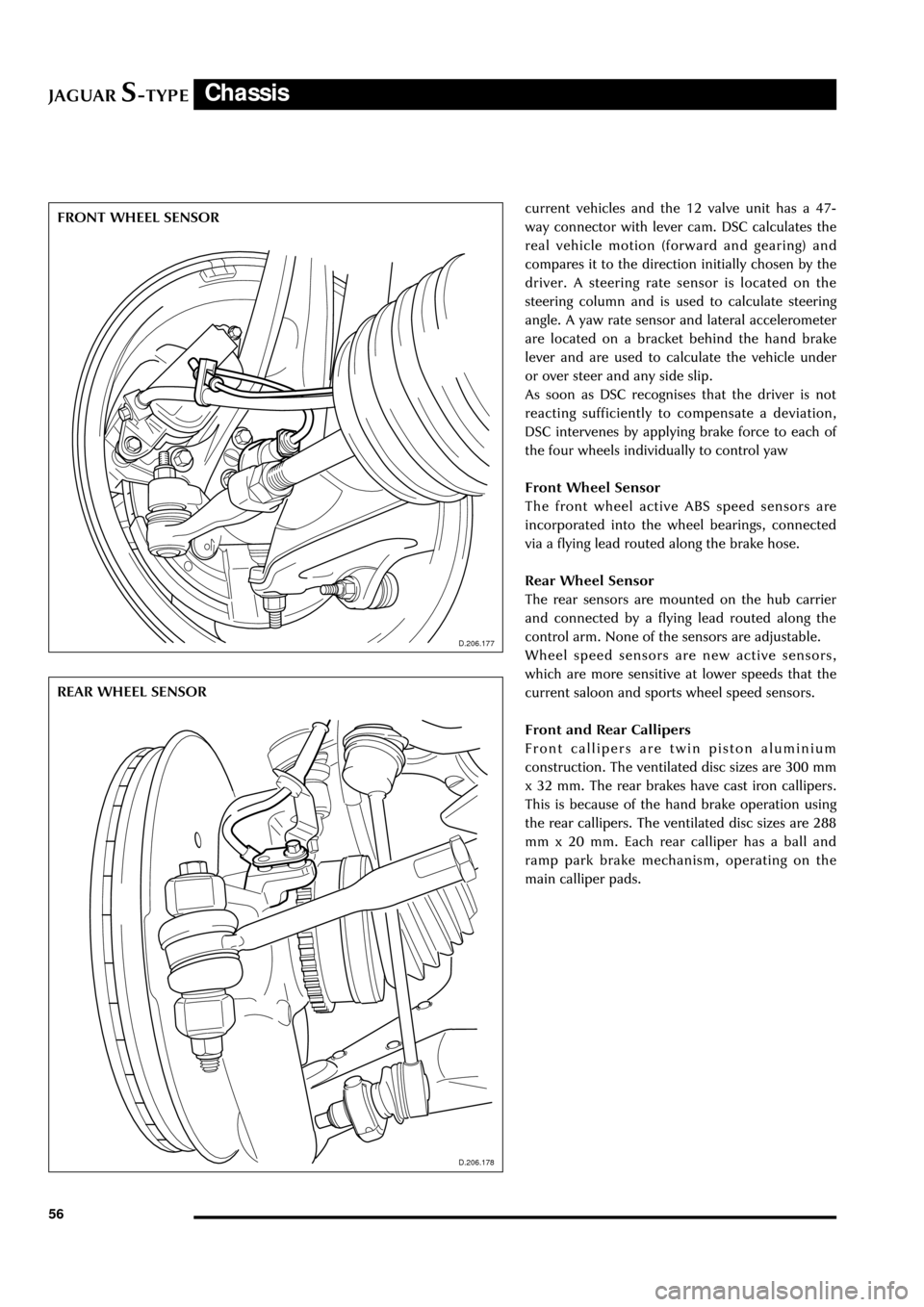
Front Wheel Sensor
The front wheel active ABS speed sensors are
incorporated into the wheel bearings, connected
via a flying lead routed along the brake hose.
Rear Wheel Sensor
The rear sensors are mounted on the hub carrier
and connected by a flying lead routed along the
control arm. None of the sensors are adjustable.
Wheel speed sensors are new active sensors,
which are more sensitive at lower speeds that the
current saloon and sports wheel speed sensors.
Front and Rear Callipers
Front callipers are twin piston aluminium
construction. The ventilated disc sizes are 300 mm
x 32 mm. The rear brakes have cast iron callipers.
This is because of the hand brake operation using
the rear callipers. The ventilated disc sizes are 288
mm x 20 mm. Each rear calliper has a ball and
ramp park brake mechanism, operating on the
main calliper pads.
D.206.178
D.206.177
FRONT WHEEL SENSOR
REAR WHEEL SENSOR
D.206.178
Page 65 of 133
JAGUARS-TYPEChassis
60
D.211.255
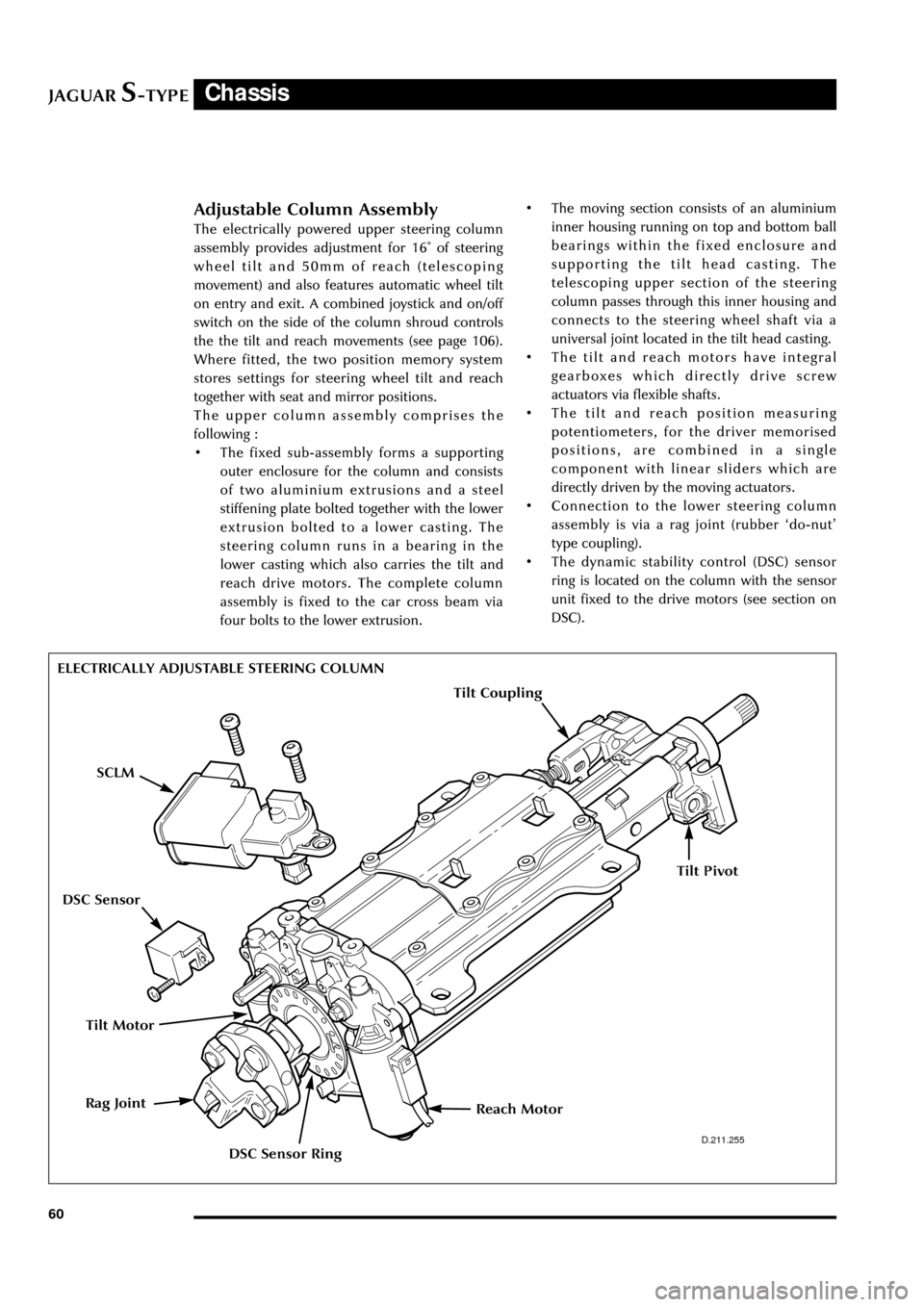
ELECTRICALLY ADJUSTABLE STEERING COLUMN
Adjustable Column Assembly
The electrically powered upper steering column
assembly provides adjustment for 16û of steering
wheel tilt and 50mm of reach (telescoping
movement) and also features automatic wheel tilt
on entry and exit. A combined joystick and on/off
switch on the side of the column shroud controls
the the tilt and reach movements (see page 106).
Where fitted, the two position memory system
stores settings for steering wheel tilt and reach
together with seat and mirror positions.
The upper column assembly comprises the
following :
¥ The fixed sub-assembly forms a supporting
outer enclosure for the column and consists
of two aluminium extrusions and a steel
stiffening plate bolted together with the lower
extrusion bolted to a lower casting. The
steering column runs in a bearing in the
lower casting which also carries the tilt and
reach drive motors. The complete column
assembly is fixed to the car cross beam via
four bolts to the lower extrusion.¥ The moving section consists of an aluminium
inner housing running on top and bottom ball
bearings within the fixed enclosure and
supporting the tilt head casting. The
telescoping upper section of the steering
column passes through this inner housing and
connects to the steering wheel shaft via a
universal joint located in the tilt head casting.
¥ The tilt and reach motors have integral
gearboxes which directly drive screw
actuators via flexible shafts.
¥ The tilt and reach position measuring
potentiometers, for the driver memorised
positions, are combined in a single
component with linear sliders which are
directly driven by the moving actuators.
¥ Connection to the lower steering column
assembly is via a rag joint (rubber Ôdo-nutÕ
type coupling).
¥ The dynamic stability control (DSC) sensor
ring is located on the column with the sensor
unit fixed to the drive motors (see section on
DSC).
Tilt Motor
Reach MotorRag Joint
SCLM
DSC Sensor Ring
DSC Sensor
Tilt Coupling
Tilt Pivot
Page 79 of 133

JAGUARS-TYPEElectrical/Electronic
74The SCP communication network will remain
operational even with severing of one of the bus
wires. Communications will also continue if one
of the bus wires is shorted to ground or battery
positive voltage (B+), or if some , but not all,
termination resistors are lost.
Unlike the SCP communication network, the
ISO 9141 communication network will not
function if the wire is shorted to ground or battery
positive voltage (B+). Also, if one of the modules
on the ISO 9141 network loses power or shorts
internally, communication to that module will fail.
Control Modules
The vehicle control module functions are
described briefly below (for further information
refer to the relevant sections throughout the
Guide).
Anti Lock Brake/Traction Control and
Dynamic Stability Control, Control Modules
The anti-lock brake control module is connected
to the SCP communication network. The module
comes in two forms. The first type is the standard
equipped anti-lock brake system (ABS) with
traction control (TC). It controls the brake
pressure to the four wheels to keep the vehicle
under control while braking.
The second type of ABS is optional and is called
dynamic stability control (DSC). This control
module adds yaw sensors to the package to help
in sensing a loss of vehicle control.
Audio Control Unit
The audio control unit is connected to the SCP
communication network and also to the audio
control protocol (ACP) communication network.
The audio control unit communicates with the
compact disc and the cellular phone transceiver.
Driver Door Control Module (DDCM)
DDCM is connected to the SCP communication
network. The module controls many functions
including power windows, driver mirror, power
locks, and keyless remote entry.Driver Seat Control Module (DSCM)
The DSCM is connected to the SCP
communication network. The DSCM is located
under the driver seat and controls the seat
positions. The module also communicates with the
DDCM to control the driver seat memory
functions.
Control Module Locations
Key to illustration on following page:
1.Anti-lock brake system/Traction control
system or Dynamic stability control
(ABS/TCCM or DSCCM)
(non-handed)
2.Throttle actuator control module (TACM)
(non-handed)
3.Powertrain control module (PCM) (handed)
4.Air conditioning control module (A/CCM)
(non-handed)
5.Restraint control module (RCM) (non-handed)
6.Sliding roof control module (SRCM)
(non-handed)
7.Passenger seat heater control module
(PSHCM) (non-handed)
8.Rear electronic control module (RECM)
(non-handed)
9.Vehicle information control module (VICM)
(Japan only)
10.Adaptive damping control module (ADCM)
(non-handed)
11.Parking aid control module (PACM)
(non-handed)
12.Navigation control module (NCM)
(non-handed)
13.Vehicle emergency control module (VECM)
(non-handed)
14.Voice-activated control module (VACM)
(non-handed)
15.Cellular telephone control module (CTCM)
(non-handed)
16.Driver seat heater control module (DSHCM)
(non-handed)
17.Driver seat control module (DSCM) (handed)
18.Driver door control module (DDCM)
(handed)
19.Instrument pack (handed)
20.General electronics control module (GECM)
(non-handed)
21.Steering column lock module (SCLM) (handed)
Page 107 of 133
JAGUARS-TYPEElectrical/Electronic
102
Door Switchpacks, Front & Rear
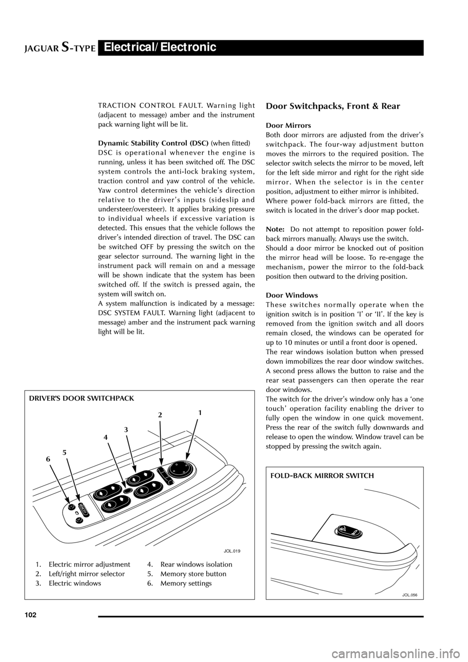
Door Mirrors
Both door mirrors are adjusted from the driverÕs
switchpack. The four-way adjustment button
moves the mirrors to the required position. The
selector switch selects the mirror to be moved, left
for the left side mirror and right for the right side
mirror. When the selector is in the center
position, adjustment to either mirror is inhibited.
Where power fold-back mirrors are fitted, the
switch is located in the driverÕs door map pocket.
Note:Do not attempt to reposition power fold-
back mirrors manually. Always use the switch.
Should a door mirror be knocked out of position
the mirror head will be loose. To re-engage the
mechanism, power the mirror to the fold-back
position then outward to the driving position.
Door Windows
These switches normally operate when the
ignition switch is in position ÔIÕ or ÔIIÕ. If the key is
removed from the ignition switch and all doors
remain closed, the windows can be operated for
up to 10 minutes or until a front door is opened.
The rear windows isolation button when pressed
down immobilizes the rear door window switches.
A second press allows the button to raise and the
rear seat passengers can then operate the rear
door windows.
The switch for the driverÕs window only has a Ôone
touchÕ operation facility enabling the driver to
fully open the window in one quick movement.
Press the rear of the switch fully downwards and
release to open the window. Window travel can be
stopped by pressing the switch again. TRACTION CONTROL FAULT. Warning light
(adjacent to message) amber and the instrument
pack warning light will be lit.
Dynamic Stability Control (DSC) (when fitted)
DSC is operational whenever the engine is
running, unless it has been switched off. The DSC
system controls the anti-lock braking system,
traction control and yaw control of the vehicle.
Yaw control determines the vehicleÕs direction
relative to the driverÕs inputs (sideslip and
understeer/oversteer). It applies braking pressure
to individual wheels if excessive variation is
detected. This ensues that the vehicle follows the
driverÕs intended direction of travel. The DSC can
be switched OFF by pressing the switch on the
gear selector surround. The warning light in the
instrument pack will remain on and a message
will be shown indicate that the system has been
switched off. If the switch is pressed again, the
system will switch on.
A system malfunction is indicated by a message:
DSC SYSTEM FAULT. Warning light (adjacent to
message) amber and the instrument pack warning
light will be lit.
JOL.019
1. Electric mirror adjustment
2. Left/right mirror selector
3. Electric windows4. Rear windows isolation
5. Memory store button
6. Memory settings DRIVERÕS DOOR SWITCHPACK
1
2
6543
JOL.056
FOLD-BACK MIRROR SWITCH
Page 116 of 133
JAGUARS-TYPEElectrical/Electronic
111 Steering Column Lock
The steering column lock is remote from the
ignition switch and controlled electronically.
When the ignition key is removed from the
ignition switch the steering column lock is
engaged. The lock is disengaged when the key is
placed in the ignition switch.
The lock can be clearly heard as it engages and
disengages.
In rare circumstances it may be necessary to
gently turn the steering wheel from side to side to
release the steering column lock.
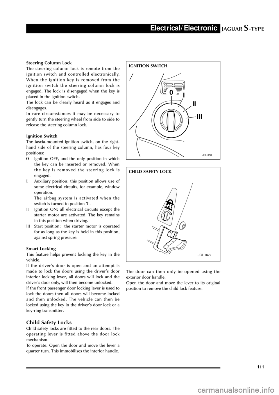
Ignition Switch
The fascia-mounted ignition switch, on the right-
hand side of the steering column, has four key
positions:
0Ignition OFF, and the only position in which
the key can be inserted or removed. When
the key is removed the steering lock is
engaged.
IAuxiliary position: this position allows use of
some electrical circuits, for example, window
operation.
The airbag system is activated when the
switch is turned to position ÔIÕ.
II Ignition ON: all electrical circuits except the
starter motor are activated. The key remains
in this position when driving.
III Start position: the starter motor is operated
for as long as the key is held in this position,
against spring pressure.
Smart Locking
This feature helps prevent locking the key in the
vehicle.
If the driverÕs door is open and an attempt is
made to lock the doors using the driverÕs door
interior locking lever, all doors will lock and the
driverÕs door only, will then become unlocked.
If the front passenger door locking lever is used to
lock the doors then all doors will become locked
and then unlocked. The vehicle can then be
locked using the key in the driverÕs door lock or a
key-ring transmitter.
Child Safety Locks
Child safety locks are fitted to the rear doors. The
operating lever is fitted above the door lock
mechanism.
To operate: Open the door and move the lever a
quarter turn. This immobilises the interior handle.
JOL.050
IGNITION SWITCH
JOL.048
The door can then only be opened using the
exterior door handle.
Open the door and move the lever to its original
position to remove the child lock feature.CHILD SAFETY LOCK
Page 121 of 133
JAGUARS-TYPEElectrical/Electronic
116
Audio and Communications System
General
The Jaguar sound system is available in two
versions: the Base System and the Premium
System. The audio head unit with integral
amplifier is located in the center stack. The audio
system has a phone interface to access stored
numbers. The antenna module is located on the
vertical panel under the rear parcel shelf
(accessed from the LHS of the trunk), FM and AM
antenna elements are in the rear screen. Four
twin cone 5in x 7in (127mm x 178mm) door
speakers are a modular cassette type for ease of
assembly/disassembly. The assembly consists of a
driverÕs door module (driverÕs door only), speaker,
and wiring and is mounted to the inner door
moulding. A special seal is kept under tension to
avoid water ingress.
JOL.040
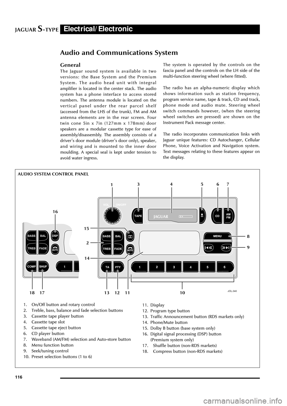
1. On/Off button and rotary control
2. Treble, bass, balance and fade selection buttons
3. Cassette tape player button
4. Cassette tape slot
5. Cassette tape eject button
6. CD player button
7. Waveband (AM/FM) selection and Auto-store button
8. Menu function button
9. Seek/tuning control
10. Preset selection buttons (1 to 6)11. Display
12. Program type button
13. Traffic Announcement button (RDS markets only)
14. Phone/Mute button
15. Dolby B button (base system only)
16. Digital signal processing (DSP) button
(Premium system only)
17. Shuffle button (non-RDS markets)
18. Compress button (non-RDS markets)The system is operated by the controls on the
fascia panel and the controls on the LH side of the
multi-function steering wheel (where fitted).
The radio has an alpha-numeric display which
shows information such as station frequency,
program service name, tape & track, CD and track,
phone mode and audio mute. Steering wheel
switch commands however, (when the steering
wheel switches are pressed) are shown on the
Instrument Pack message center.
The radio incorporates communication links with
Jaguar unique features: CD Autochanger, Cellular
Phone, Voice Activation and Navigation system.
Text messages relating to these features appear on
the display.
1
26 5 4 3
109 8 7
11 13 12 1814 16
15
17 AUDIO SYSTEM CONTROL PANEL
Page 122 of 133
JAGUARS-TYPEElectrical/Electronic
117 The radio volume is muted to a low level when:
the Reverse Park Control is enabled by engaging
reverse gear, the Cellular phone in hands-free
mode is used, the Navigation system delivers
audible route guidance instructions or the Voice
activation system requests listening or verbal
feedback.
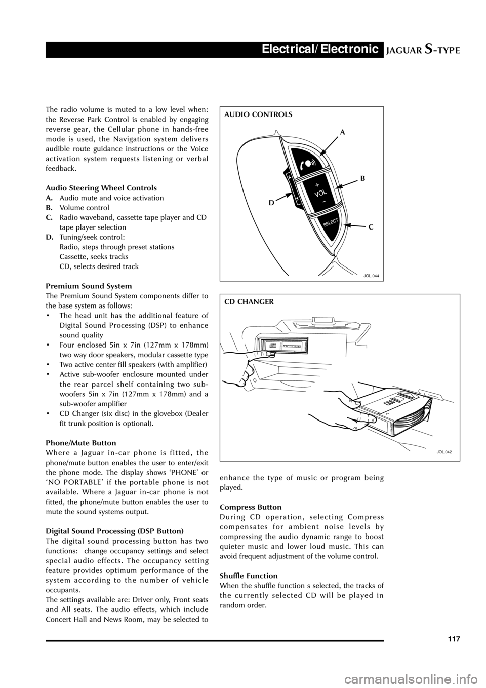
Audio Steering Wheel Controls
A.Audio mute and voice activation
B.Volume control
C.Radio waveband, cassette tape player and CD
tape player selection
D.Tuning/seek control:
Radio, steps through preset stations
Cassette, seeks tracks
CD, selects desired track
Premium Sound System
The Premium Sound System components differ to
the base system as follows:
¥ The head unit has the additional feature of
Digital Sound Processing (DSP) to enhance
sound quality
¥ Four enclosed 5in x 7in (127mm x 178mm)
two way door speakers, modular cassette type
¥ Two active center fill speakers (with amplifier)
¥ Active sub-woofer enclosure mounted under
the rear parcel shelf containing two sub-
woofers 5in x 7in (127mm x 178mm) and a
sub-woofer amplifier
¥ CD Changer (six disc) in the glovebox (Dealer
fit trunk position is optional).
Phone/Mute Button
Where a Jaguar in-car phone is fitted, the
phone/mute button enables the user to enter/exit
the phone mode. The display shows ÔPHONEÕ or
ÔNO PORTABLEÕ if the portable phone is not
available. Where a Jaguar in-car phone is not
fitted, the phone/mute button enables the user to
mute the sound systems output.
Digital Sound Processing (DSP Button)
The digital sound processing button has two
functions: change occupancy settings and select
special audio effects. The occupancy setting
feature provides optimum performance of the
system according to the number of vehicle
occupants.
The settings available are: Driver only, Front seats
and All seats. The audio effects, which include
Concert Hall and News Room, may be selected to
JOL.042
enhance the type of music or program being
played.
Compress Button
During CD operation, selecting Compress
compensates for ambient noise levels by
compressing the audio dynamic range to boost
quieter music and lower loud music. This can
avoid frequent adjustment of the volume control.
Shuffle Function
When the shuffle function s selected, the tracks of
the currently selected CD will be played in
random order.
A
D
C B AUDIO CONTROLS
CD CHANGER
JOL.044