fuel door JAGUAR S TYPE 2005 1.G Technical Guide Update
[x] Cancel search | Manufacturer: JAGUAR, Model Year: 2005, Model line: S TYPE, Model: JAGUAR S TYPE 2005 1.GPages: 133, PDF Size: 3.48 MB
Page 6 of 133

Contents
1
Subject Page
Glossary
Abbreviations 3
Introduction4
Vehicle Weights 5
Dimensions 5
Vehicle Features 6
Body
Body Structure 10
Engine Compartment 15
Trunk 16
Jacking and Towing 18
Glazing 19
Doors and Door Mirrors 21
Windshield Wipers and Washers 23
Exterior and Interior Trim 24
Seats 26
Interior Features 30
Occupant Protection
Seat Belts 32
Airbags 33
SRS Operation 35
Fuel System
Introduction 38
Evaporative Emissions System 42
Exhaust System
Introduction 44
Transmission
Introduction 45
Chassis
Introduction 46
Front Suspension 47
Rear Suspension 49
Wheels and Tyres 52
Driveline 53
Final Drive (differential) 54
Brakes 55
Power Assisted Steering 58
Steering Column 59
Climate Control
System Overview 63
continued:
JAGUARS-TYPE
Page 8 of 133

JAGUARS-TYPEGlossary
3 A Ab
bb
br
re
ev
vi
ia
at
ti
io
on
nD
De
es
sc
cr
ri
ip
pt
ti
io
on
n
ABS anti-lock braking system
ABS/TCCM anti-lock braking system/
traction control system control
module
A/C air conditioning
A/CCM air conditioning control
module
ADCM adaptive damping control
module
ADRC adaptive damper ride control
ALR automatic locking retractor
BIW body-in-white
ûC degree Celsius
CAN controller area network
CATS computer active technology
suspension
CD compact disc
CTCM cellular telephone control
module
DATC dual automatic temperature
control
DDCM driver door control module
DSC(CM) dynamic stability control
(control module)
DSCM driver seat control module
DSHCM driver seat heater control
module
ECM electronic control module
EFT engine fuel temperature
(sensor)
EVAP evaporative emission
FTP fuel tank pressure (sensor)
GDO garage door opener
GECM general electronic control
module
GPS global positioning system
HO2S heated oxygen sensor
in inch
IP injection pressure (sensor)
IVD interactive vehicle dynamics
kg kilogram
km/h kilometer per hour
kW kilowatt
lb pound
m meter The following abbreviations are used in this document:
A Ab
bb
br
re
ev
vi
ia
at
ti
io
on
nD
De
es
sc
cr
ri
ip
pt
ti
io
on
n
LH(D) left-hand (drive)
mile/h mile per hour
mm millimeter
ms millisecond
NAS North American specification
NCM navigation control module
Nm Newton meter
OBD on-board diagnostics
PAS power assisted steering
PATS passive anti-theft system
PCM powertrain control module
PDU portable diagnostic unit
PSHCM passenger seat heater control
module
RECM rear electronic control module
RCM restraints control module
RH(D) right-hand (drive)
RPC(M) reverse park control (module)
RTTI real time traffic information
SAE Society of Automotive Engineers
SCLM steering column lock module
SCP standard corporate protocol
SRCM sliding roof control module
SRS supplementary restraints
system
TACM throttle actuator control
module
UK United Kingdom
USA United States of America
V volt
VACM voice-activated control module
VECM vehicle emergency control
module
VEMS vehicle emergency messaging
system
VICM vehicle information control
module
VICS vehicle information and
communication system
VIN vehicle identification number
Page 17 of 133

JAGUARS-TYPEBody
12
Front and Centre Floor Pan
The floor pan is a three-piece construction with
handed dash panels, welded front suspension
housing, an integral centre bearing panel for the
driveshaft and a large under-tunnel heatshield.
Rear Floor Pan
Multi-piece floor pan design, the rear tub is
designed to accept either a full size or space saver
spare wheel and the luggage compartment has
four tie-down luggage loops. Two plastic covers
are located under the rear seat and these give
easy access to the fuel tank mounted components.
A plastic battery tray is located below the luggage
load floor.
Roof
Provision has been made for roof rack fixings and
the roof has reinforcement for vehicles fitted with
a the sliding roof.
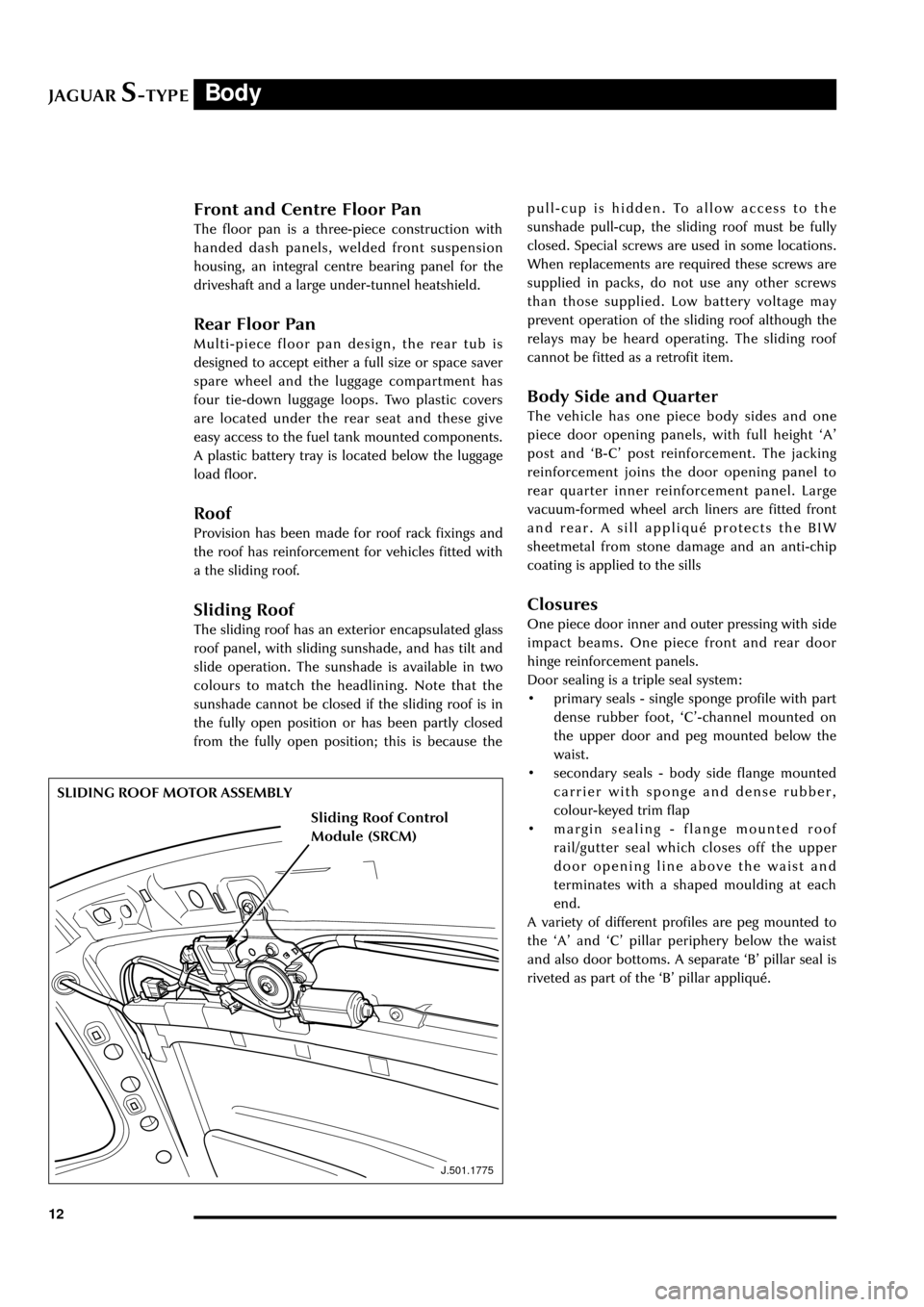
Sliding Roof
The sliding roof has an exterior encapsulated glass
roof panel, with sliding sunshade, and has tilt and
slide operation. The sunshade is available in two
colours to match the headlining. Note that the
sunshade cannot be closed if the sliding roof is in
the fully open position or has been partly closed
from the fully open position; this is because the
J.501.1775
SLIDING ROOF MOTOR ASSEMBLYpull-cup is hidden. To allow access to the
sunshade pull-cup, the sliding roof must be fully
closed. Special screws are used in some locations.
When replacements are required these screws are
supplied in packs, do not use any other screws
than those supplied. Low battery voltage may
prevent operation of the sliding roof although the
relays may be heard operating. The sliding roof
cannot be fitted as a retrofit item.
Body Side and Quarter
The vehicle has one piece body sides and one
piece door opening panels, with full height ÔAÕ
post and ÔB-CÕ post reinforcement. The jacking
reinforcement joins the door opening panel to
rear quarter inner reinforcement panel. Large
vacuum-formed wheel arch liners are fitted front
and rear. A sill appliquŽ protects the BIW
sheetmetal from stone damage and an anti-chip
coating is applied to the sills
Closures
One piece door inner and outer pressing with side
impact beams. One piece front and rear door
hinge reinforcement panels.
Door sealing is a triple seal system:
¥ primary seals - single sponge profile with part
dense rubber foot, ÔCÕ-channel mounted on
the upper door and peg mounted below the
waist.
¥ secondary seals - body side flange mounted
carrier with sponge and dense rubber,
colour-keyed trim flap
¥ margin sealing - flange mounted roof
rail/gutter seal which closes off the upper
door opening line above the waist and
terminates with a shaped moulding at each
end.
A variety of different profiles are peg mounted to
the ÔAÕ and ÔCÕ pillar periphery below the waist
and also door bottoms. A separate ÔBÕ pillar seal is
riveted as part of the ÔBÕ pillar appliquŽ.
Sliding Roof Control
Module (SRCM)
Page 46 of 133

JAGUARS-TYPEFuel System
41
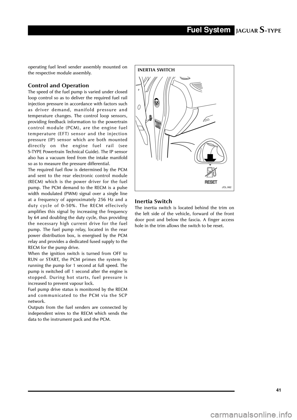
JOL.062
INERTIA SWITCH operating fuel level sender assembly mounted on
the respective module assembly.
Control and Operation
The speed of the fuel pump is varied under closed
loop control so as to deliver the required fuel rail
injection pressure in accordance with factors such
as driver demand, manifold pressure and
temperature changes. The control loop sensors,
providing feedback information to the powertrain
control module (PCM), are the engine fuel
temperature (EFT) sensor and the injection
pressure (IP) sensor which are both mounted
directly on the engine fuel rail (see
S-TYPE Powertrain Technical Guide). The IP sensor
also has a vacuum feed from the intake manifold
so as to measure the pressure differential.
The required fuel flow is determined by the PCM
and sent to the rear electronic control module
(RECM) which is the power driver for the fuel
pump. The PCM demand to the RECM is a pulse
width modulated (PWM) signal over a single line
at a frequency of approximately 256 Hz and a
duty cycle of 0-50%. The RECM effecively
amplifies this signal by increasing the frequency
by 64 and doubling the duty cycle, thus providing
the necessary high current drive for the fuel
pump. The fuel pump relay, located in the rear
power distribution box, is energised by the PCM
relay and provides a dedicated fused supply to the
RECM for the pump drive.
When the ignition switch is turned from OFF to
RUN or START, the PCM primes the system by
running the pump for 1 second at full speed. The
pump is switched off 1 second after the engine is
stopped. During hot starts, fuel pressure is
increased to prevent vapour lock.
Fuel pump drive status is monitored by the RECM
and communicated to the PCM via the SCP
network.
Outputs from the fuel senders are connected by
independent wires to the RECM which sends the
data to the instrument pack and the PCM.
Inertia Switch
The inertia switch is located behind the trim on
the left side of the vehicle, forward of the front
door post and below the fascia. A finger access
hole in the trim allows the switch to be reset.
Page 81 of 133

JAGUARS-TYPEElectrical/Electronic
76Air Conditioning Control Module (A/CCM)
The A/CCM is connected to the SCP
communication network. The A/CCM controls
automatic climate functions that maintain the
vehicle at a constant temperature setting.
Instrument Pack
The instrument pack is connected to the SCP
communication network. The instrument pack
displays information received on the SCP
including speedometer, odometer, fuel, and
message center warnings. The instrument pack
also controls the passive anti-theft system (PATS).
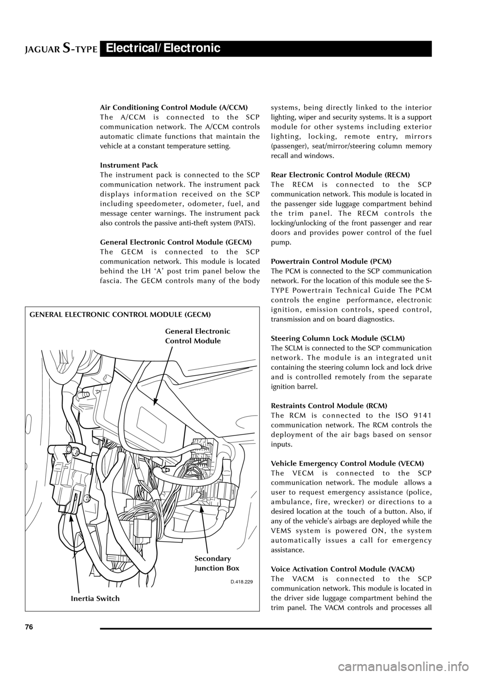
General Electronic Control Module (GECM)
The GECM is connected to the SCP
communication network. This module is located
behind the LH ÔAÕ post trim panel below the
fascia. The GECM controls many of the bodysystems, being directly linked to the interior
lighting, wiper and security systems. It is a support
module for other systems including exterior
lighting, locking, remote entry, mirrors
(passenger), seat/mirror/steering column memory
recall and windows.
Rear Electronic Control Module (RECM)
The RECM is connected to the SCP
communication network. This module is located in
the passenger side luggage compartment behind
the trim panel. The RECM controls the
locking/unlocking of the front passenger and rear
doors and provides power control of the fuel
pump.
Powertrain Control Module (PCM)
The PCM is connected to the SCP communication
network. For the location of this module see the S-
TYPE Powertrain Technical Guide The PCM
controls the engine performance, electronic
ignition, emission controls, speed control,
transmission and on board diagnostics.
Steering Column Lock Module (SCLM)
The SCLM is connected to the SCP communication
network. The module is an integrated unit
containing the steering column lock and lock drive
and is controlled remotely from the separate
ignition barrel.
Restraints Control Module (RCM)
The RCM is connected to the ISO 9141
communication network. The RCM controls the
deployment of the air bags based on sensor
inputs.
Vehicle Emergency Control Module (VECM)
The VECM is connected to the SCP
communication network. The module allows a
user to request emergency assistance (police,
ambulance, fire, wrecker) or directions to a
desired location at the touch of a button. Also, if
any of the vehicleÕs airbags are deployed while the
VEMS system is powered ON, the system
automatically issues a call for emergency
assistance.
Voice Activation Control Module (VACM)
The VACM is connected to the SCP
communication network. This module is located in
the driver side luggage compartment behind the
trim panel. The VACM controls and processes all
D.418.229
GENERAL ELECTRONIC CONTROL MODULE (GECM)
Inertia Switch
Secondary
Junction Box
General Electronic
Control Module
Page 87 of 133

JAGUARS-TYPEElectrical/Electronic
82No Type Rating (amps) Colour Circuit
15 mini 5 Brown Adaptive damping module (ADRC)
16 mini 5 Brown Heated seat switch module,
electrochromic mirror, rain sensor
17 mini 5 Brown RCM, Generator warning lamp
18 mini 20 Yellow Radio, cellular phone, navigation unit
19 mini 15 Blue Steering column motors
20 mini 10 Red GECM, DATC, RECM, Instrument Pack,
brake shift interlock
21 mini 10 Red Power folding mirrors, electric sunblind
22 mini 10 Red DriverÕs door mirror, driverÕs door lock
motor
23 mini 10 Red Right-front high beam
24 mini 5 Brown Passive Anti-Theft System (PATS)
25 mini 10 Red Left-front low beam headlamp
26 - - - Not used
27 mini 10 Red Navigation display, radio, phone,
navigation module, Traffic Master
28 mini 5 Brown Battery-backed security sounder
29 mini 5 Brown Voice control, reversing aid, GECM,
Trailer tow ignition sense, VEMS
30 mini 5 Brown GECM
31 - - - Not used
32 mini 20 Yellow Accessory socket, cigar lighter
33 mini 10 Red GECM illumination power
34 - - - Not used
35 mini 5 Brown Stop lamp switch
Trunk Fusebox
No Type Rating (amps) Colour Circuit
1 mini 15 Blue Luggage compartment release solenoid
2 mini 10 Red Right rear direction indicators, back up,
fog lamps, side markers
3 mini 10 Red Left stop lamp
4 mini 10 Red Fuel door release solenoid
5 mini 10 Red Courtesy and map lamps
6 mini 10 Red Left rear direction indicators, back up,
fog lamps, side markers
7 mini 10 Red Right stop lamp
8 mini 10 Red Center high mounted stop lamp
9 mini 5 Brown Heated mirror
10 mini 5 Brown Traffic Master
11 mini 15 Blue Heated seats
Page 88 of 133

JAGUARS-TYPEElectrical/Electronic
83 No Type Rating (amps) Colour Circuit
12 mini 5 Brown RECM - logic, Transit relay
13 mini 15 Blue Adaptive damper ride control (ADRC)
14 mini 5 Brown Phone, CD, Vehicle emergency message
system (VEMS)
15 mini 5 Brown Alternator sense
16 mini 20 Yellow Sliding roof
17 mini 15 Blue Fuel pump
18 mini 20 Yellow Subwoofer amplifier
19 cartridge 20 Blue RECM, left rear window
20 cartridge 30 Pink Driver door module - Driver window
21 cartridge 30 Pink Driver lumbar
22 cartridge 20 Blue Ignition
23 cartridge 30 Pink Switched system power 4
24 cartridge 30 Pink Switched system power 3
25 cartridge 40 Green Primary junction box
26 cartridge 30 Pink GECM Passenger window
(30amp early cars)
27 cartridge 30 Pink RECM, right rear window
28 cartridge 30 Pink Passenger lumbar
29 cartridge 30 Pink Rear defroster
30 cartridge 20 Blue Switched system power 1
31 cartridge 30 Pink Switched system power 2
32 - - - Unused
Diode 01 Unused
Diode 02 1 Fuel pump motor
Page 101 of 133

JAGUARS-TYPEElectrical/Electronic
96
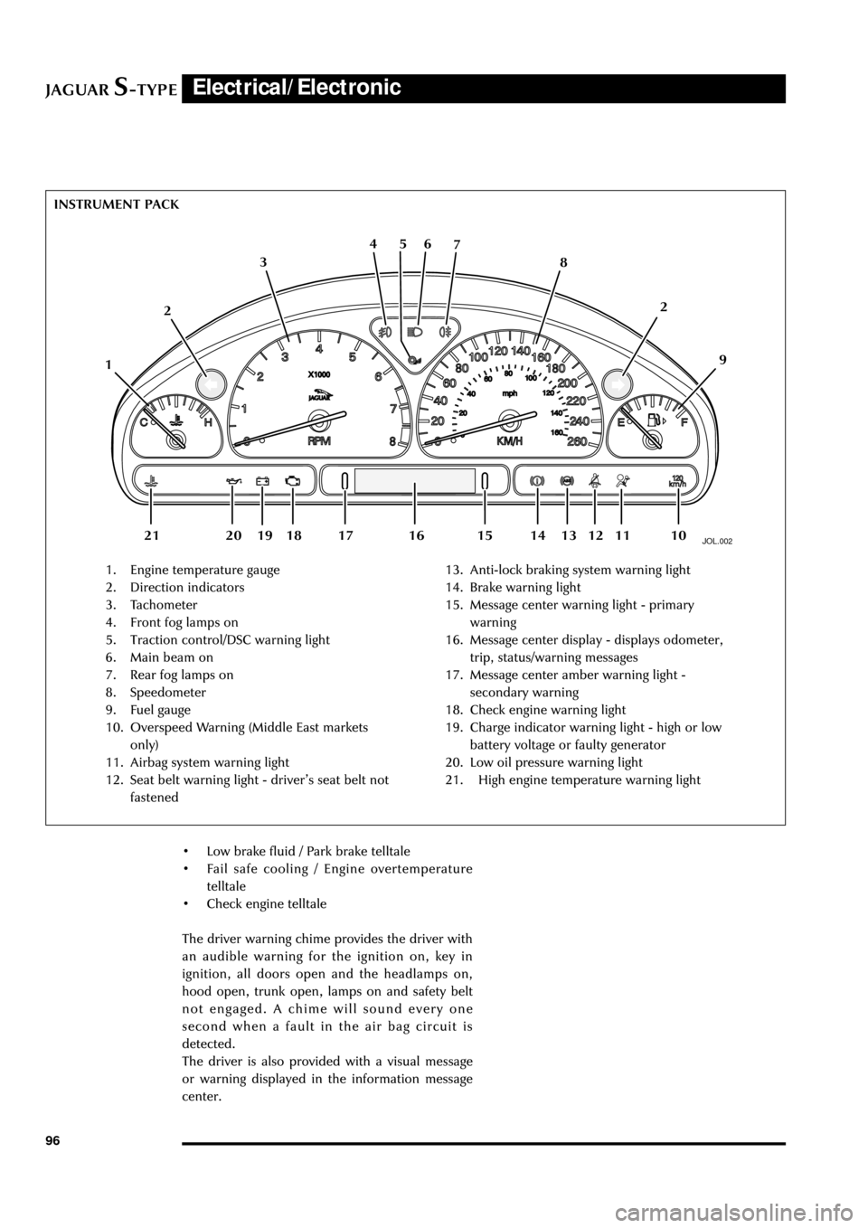
JOL.002
1. Engine temperature gauge
2. Direction indicators
3. Tachometer
4. Front fog lamps on
5. Traction control/DSC warning light
6. Main beam on
7. Rear fog lamps on
8. Speedometer
9. Fuel gauge
10. Overspeed Warning (Middle East markets
only)
11. Airbag system warning light
12. Seat belt warning light - driverÕs seat belt not
fastened13. Anti-lock braking system warning light
14. Brake warning light
15. Message center warning light - primary
warning
16. Message center display - displays odometer,
trip, status/warning messages
17. Message center amber warning light -
secondary warning
18. Check engine warning light
19. Charge indicator warning light - high or low
battery voltage or faulty generator
20. Low oil pressure warning light
21. High engine temperature warning light INSTRUMENT PACK
126 5 4
3
109 8 7
112
13 12 18 20 19 1416 15 17 21
¥ Low brake fluid / Park brake telltale
¥ Fail safe cooling / Engine overtemperature
telltale
¥ Check engine telltale
The driver warning chime provides the driver with
an audible warning for the ignition on, key in
ignition, all doors open and the headlamps on,
hood open, trunk open, lamps on and safety belt
not engaged. A chime will sound every one
second when a fault in the air bag circuit is
detected.
The driver is also provided with a visual message
or warning displayed in the information message
center.
Page 113 of 133

JAGUARS-TYPEElectrical/Electronic
108
Security and Locking Systems
Introduction
The following security and locking features are
available but vary by market or options:
¥ Key barrel on driverÕs side only
¥ Encrypted engine immobilization by ignition
key transponder
¥ Radio frequency remote fob
¥ Central locking by key and remote fob
¥ Double locking (not in North America, Japan,
Taiwan)
¥ Drive away door locking
¥ Mechanical child locks on rear doors
¥ Perimeter alarm of doors, bonnet, trunk
¥ Intrusion sensing, ultrasonically sensed (not
in North America, Japan, Taiwan)
¥ Inclination (tilt) sensing (Dealer fit accessory)
¥ Panic alarm, fob operated (certain markets)
¥ Trunk lock isolate (valet lockout, see page
107) - North America only
¥ Electro/mechanical steering column lock
The following convenience features are included
either as standard or optional features:
¥ Remote fob operated driverÕs seat, door
mirrors and steering column memory recall
(two memories)
¥ Remote fob operated trunk lid release
¥ Key operated global close (sliding roof and all
windows)
¥ Key and fob remote-operated global open
(sliding roof and all windows)
¥ Trunk lid and fuel flap interior release buttons
¥ Trunk release button in trunk plinth
¥ Emergency key lock barrel under trunk plinth.
System Description
The security system is controlled by a driver door
control module (DDCM). When activated
unauthorized entry in to the vehicle is detected by
the courtesy lamp switches. When the alarm is
triggered, the system flashes the turn signal lamps
and sounds the alarm system horns.
The passive anti-theft system (PATS) is a feature to
prevent the vehicle being driven away by an
unauthorized person. The PATS system consists of
electronically coded keys, a transceiver and is
controlled by the Instrument Pack. When the
ignition is switched to position ÔIIÕ, the transceiver
energises the ignition key to read its electroniccode that is transmitted back. If the read code
equals a stored code in the control module, the
steering column is unlocked and the powertrain
control module (PCM) will let the engine start.
Otherwise, starting of the engine is disabled
(through the starter disable relay and the PCM).
The security indicator LED provides the driver
with the status of the PATS or security system. If
the security system is armed the light will flash
when the ignition is switched OFF. The PATS light
will illuminate when the key is inserted into the
ignition lock and turned to position ÔIIÕ. It will stay
illuminated until the system has carried out its test
on the key. If the system detects a fault, it will
flash the LED for 1 minute, and then flash out the
corresponding 2 digit fault code.
Security System Operating Components
Key to illustration on the following page:
1. Four button transmitter (North America/Rest
of the World)
2. Three button transmitter (Europe/Japan)
3. Trunk release switch
4. Trunk compartment actuator
5. Intrusion sensor
6. Door actuator
7. Driver door control module
8. Data link connector
9. General electronic control module
10. PATS transceiver module
11. Hood switch
12. Security LED
13. Horns
14. Security horn
15. Security sounder
16. Intrusion sensor
17. Rear electronic control module