low beam JAGUAR S TYPE 2005 1.G Technical Guide Update
[x] Cancel search | Manufacturer: JAGUAR, Model Year: 2005, Model line: S TYPE, Model: JAGUAR S TYPE 2005 1.GPages: 133, PDF Size: 3.48 MB
Page 17 of 133
JAGUARS-TYPEBody
12
Front and Centre Floor Pan
The floor pan is a three-piece construction with
handed dash panels, welded front suspension
housing, an integral centre bearing panel for the
driveshaft and a large under-tunnel heatshield.
Rear Floor Pan
Multi-piece floor pan design, the rear tub is
designed to accept either a full size or space saver
spare wheel and the luggage compartment has
four tie-down luggage loops. Two plastic covers
are located under the rear seat and these give
easy access to the fuel tank mounted components.
A plastic battery tray is located below the luggage
load floor.
Roof
Provision has been made for roof rack fixings and
the roof has reinforcement for vehicles fitted with
a the sliding roof.
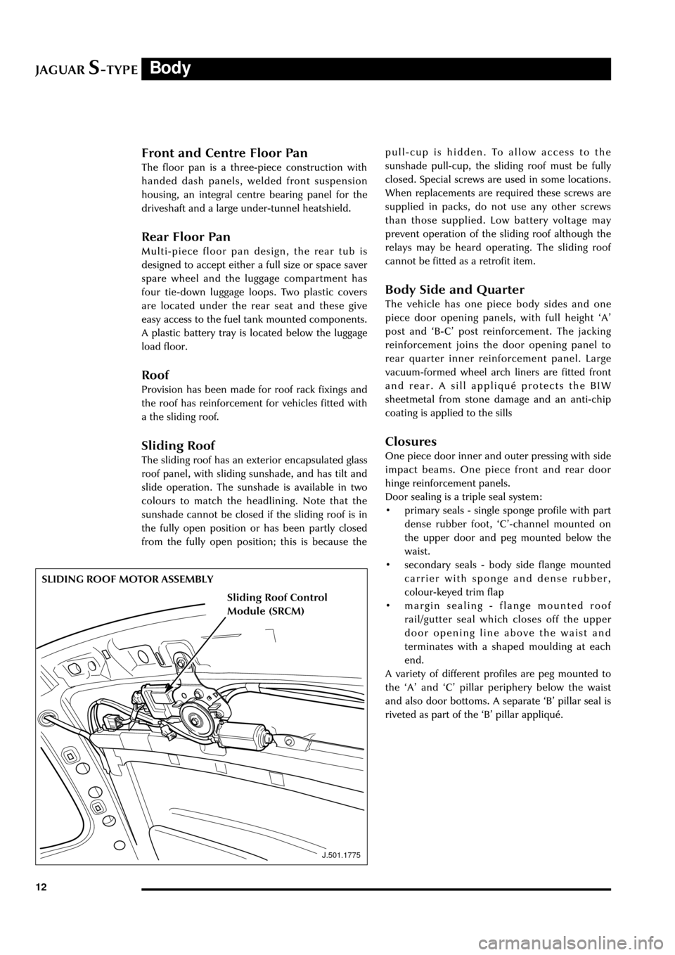
Sliding Roof
The sliding roof has an exterior encapsulated glass
roof panel, with sliding sunshade, and has tilt and
slide operation. The sunshade is available in two
colours to match the headlining. Note that the
sunshade cannot be closed if the sliding roof is in
the fully open position or has been partly closed
from the fully open position; this is because the
J.501.1775
SLIDING ROOF MOTOR ASSEMBLYpull-cup is hidden. To allow access to the
sunshade pull-cup, the sliding roof must be fully
closed. Special screws are used in some locations.
When replacements are required these screws are
supplied in packs, do not use any other screws
than those supplied. Low battery voltage may
prevent operation of the sliding roof although the
relays may be heard operating. The sliding roof
cannot be fitted as a retrofit item.
Body Side and Quarter
The vehicle has one piece body sides and one
piece door opening panels, with full height ÔAÕ
post and ÔB-CÕ post reinforcement. The jacking
reinforcement joins the door opening panel to
rear quarter inner reinforcement panel. Large
vacuum-formed wheel arch liners are fitted front
and rear. A sill appliquŽ protects the BIW
sheetmetal from stone damage and an anti-chip
coating is applied to the sills
Closures
One piece door inner and outer pressing with side
impact beams. One piece front and rear door
hinge reinforcement panels.
Door sealing is a triple seal system:
¥ primary seals - single sponge profile with part
dense rubber foot, ÔCÕ-channel mounted on
the upper door and peg mounted below the
waist.
¥ secondary seals - body side flange mounted
carrier with sponge and dense rubber,
colour-keyed trim flap
¥ margin sealing - flange mounted roof
rail/gutter seal which closes off the upper
door opening line above the waist and
terminates with a shaped moulding at each
end.
A variety of different profiles are peg mounted to
the ÔAÕ and ÔCÕ pillar periphery below the waist
and also door bottoms. A separate ÔBÕ pillar seal is
riveted as part of the ÔBÕ pillar appliquŽ.
Sliding Roof Control
Module (SRCM)
Page 18 of 133
JAGUARS-TYPEBody
13
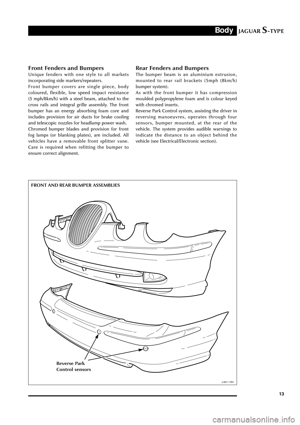
Front Fenders and Bumpers
Unique fenders with one style to all markets
incorporating side markers/repeaters.
Front bumper covers are single piece, body
coloured, flexible, low speed impact resistance
(5 mph/8km/h) with a steel beam, attached to the
cross rails and integral grille assembly. The front
bumper has an energy absorbing foam core and
includes provision for air ducts for brake cooling
and telescopic nozzles for headlamp power wash.
Chromed bumper blades and provision for front
fog lamps (or blanking plates), are included. All
vehicles have a removable front splitter vane.
Care is required when refitting the bumper to
ensure correct alignment.
Rear Fenders and Bumpers
The bumper beam is an aluminium extrusion,
mounted to rear rail brackets (5mph (8km/h)
bumper system).
As with the front bumper it has compression
moulded polypropylene foam and is colour keyed
with chromed inserts.
Reverse Park Control system, assisting the driver in
reversing manoeuvres, operates through four
sensors, bumper mounted, at the rear of the
vehicle. The system provides audible warnings to
indicate the distance to an object behind the
vehicle (see Electrical/Electronic section).
FRONT AND REAR BUMPER ASSEMBLIES
J.501.1781
Reverse Park
Control sensors
Page 54 of 133
JAGUARS-TYPEChassis
49
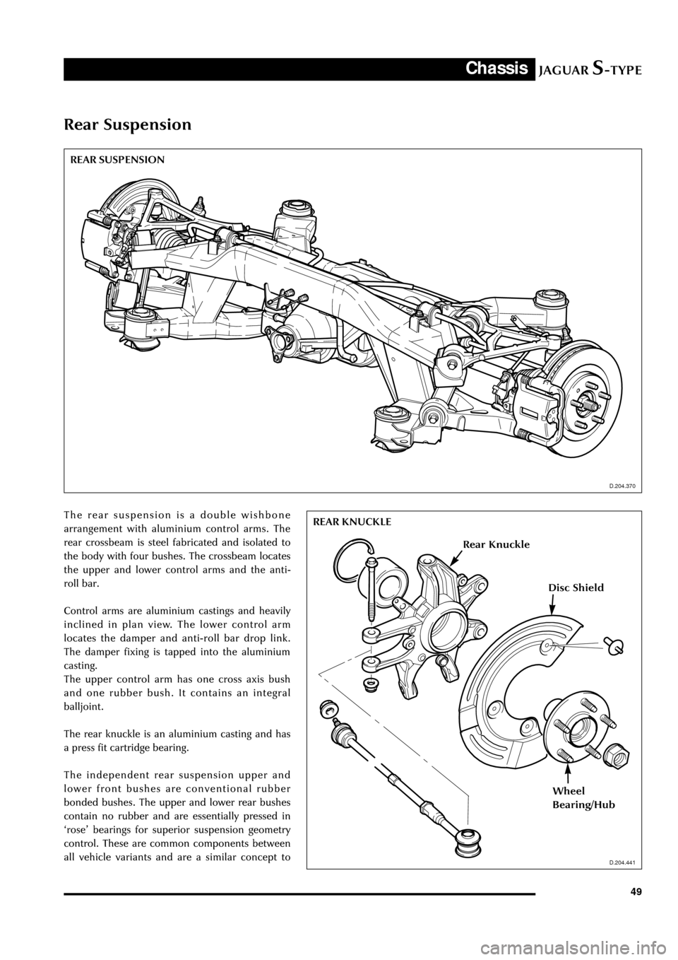
Rear Suspension
The rear suspension is a double wishbone
arrangement with aluminium control arms. The
rear crossbeam is steel fabricated and isolated to
the body with four bushes. The crossbeam locates
the upper and lower control arms and the anti-
roll bar.
Control arms are aluminium castings and heavily
inclined in plan view. The lower control arm
locates the damper and anti-roll bar drop link.
The damper fixing is tapped into the aluminium
casting.
The upper control arm has one cross axis bush
and one rubber bush. It contains an integral
balljoint.
The rear knuckle is an aluminium casting and has
a press fit cartridge bearing.
The independent rear suspension upper and
lower front bushes are conventional rubber
bonded bushes. The upper and lower rear bushes
contain no rubber and are essentially pressed in
ÔroseÕ bearings for superior suspension geometry
control. These are common components between
all vehicle variants and are a similar concept to
D.204.370
D.204.441
REAR SUSPENSION
D.204.370
REAR KNUCKLE
D.204.441
Rear Knuckle
Disc Shield
Wheel
Bearing/Hub
Page 65 of 133
JAGUARS-TYPEChassis
60
D.211.255
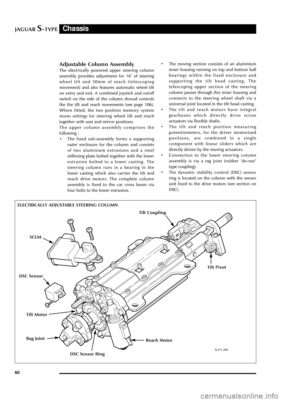
ELECTRICALLY ADJUSTABLE STEERING COLUMN
Adjustable Column Assembly
The electrically powered upper steering column
assembly provides adjustment for 16û of steering
wheel tilt and 50mm of reach (telescoping
movement) and also features automatic wheel tilt
on entry and exit. A combined joystick and on/off
switch on the side of the column shroud controls
the the tilt and reach movements (see page 106).
Where fitted, the two position memory system
stores settings for steering wheel tilt and reach
together with seat and mirror positions.
The upper column assembly comprises the
following :
¥ The fixed sub-assembly forms a supporting
outer enclosure for the column and consists
of two aluminium extrusions and a steel
stiffening plate bolted together with the lower
extrusion bolted to a lower casting. The
steering column runs in a bearing in the
lower casting which also carries the tilt and
reach drive motors. The complete column
assembly is fixed to the car cross beam via
four bolts to the lower extrusion.¥ The moving section consists of an aluminium
inner housing running on top and bottom ball
bearings within the fixed enclosure and
supporting the tilt head casting. The
telescoping upper section of the steering
column passes through this inner housing and
connects to the steering wheel shaft via a
universal joint located in the tilt head casting.
¥ The tilt and reach motors have integral
gearboxes which directly drive screw
actuators via flexible shafts.
¥ The tilt and reach position measuring
potentiometers, for the driver memorised
positions, are combined in a single
component with linear sliders which are
directly driven by the moving actuators.
¥ Connection to the lower steering column
assembly is via a rag joint (rubber Ôdo-nutÕ
type coupling).
¥ The dynamic stability control (DSC) sensor
ring is located on the column with the sensor
unit fixed to the drive motors (see section on
DSC).
Tilt Motor
Reach MotorRag Joint
SCLM
DSC Sensor Ring
DSC Sensor
Tilt Coupling
Tilt Pivot
Page 86 of 133

JAGUARS-TYPEElectrical/Electronic
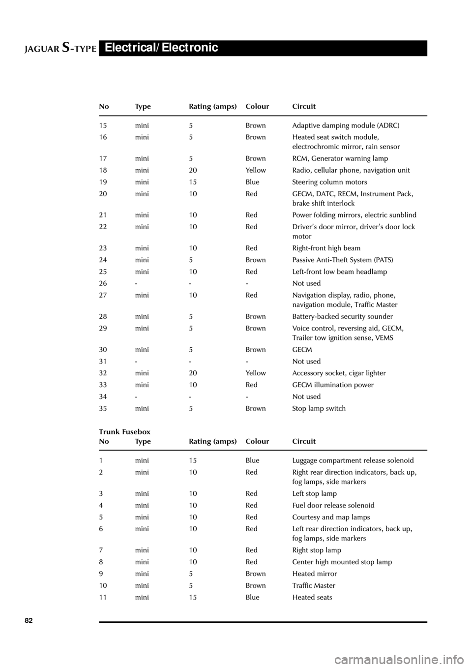
81 No Type Rating (amps) Colour Circuit
10 - - - Not used
11 mini 15 Blue HO2 sensor (catalyst)
12 mini 10 Red Coil on plug
13 cartridge 40 or 30 Green or Pink RH heated windshield or heated wiper
park (where fitted)
14 - - - Not used
15 cartridge 40 Green LH heated windshield
16 cartridge 30 Pink Blower motor
17 - - - Not used
18 cartridge 40 Green Powertrain control module (PCM)
19 - - - Not used
20 - - - Not used
21 cartridge 30 Pink Starter solenoid
22 cartridge 30 Pink ABS motor
23 cartridge 20 Blue Wiper motor
24 cartridge 30 Pink Head lamp washer pump
25 cartridge 80 - Cooling fan motor
Diode 1 PCM
Passenger Compartment Fusebox
No Type Rating (amps) Colour Circuit
1 mini 5 Brown Starter relay coil via Park/Neutral switch
2 mini 5 Brown Radio
3 mini 5 Brown ABS/DSC module
4 mini 5 Brown PCM relay coil, instrument pack, RECM,
fuel pump relay, transit relay
5 mini 5 Brown Autolamp sensor, heated seat module
switch & overdrive cancel switch RSM, BSI
6 mini 10 Red OBDII
7 mini 5 Brown DDCM, DSCM, PCM, Anti-theft LED,
security horn, power mirror
8 mini 5 Brown Right-front direction indicators, side
repeaters, side markers, park lights
9 mini 10 Red Right-front low beam headlamp
10 mini 5 Brown Left-front direction indicators side
repeaters, side markers, park lamps
11 mini 10 Red Left-front main beam lamp
12 mini 10 Red Headlamp levelling, ABS/DSC module
13 mini 5 Brown Instrument pack
14 mini 10 Red RCM, Dual Automatic Temperature
Control (DATC) module
Page 87 of 133
JAGUARS-TYPEElectrical/Electronic
82No Type Rating (amps) Colour Circuit
15 mini 5 Brown Adaptive damping module (ADRC)
16 mini 5 Brown Heated seat switch module,
electrochromic mirror, rain sensor
17 mini 5 Brown RCM, Generator warning lamp
18 mini 20 Yellow Radio, cellular phone, navigation unit
19 mini 15 Blue Steering column motors
20 mini 10 Red GECM, DATC, RECM, Instrument Pack,
brake shift interlock
21 mini 10 Red Power folding mirrors, electric sunblind
22 mini 10 Red DriverÕs door mirror, driverÕs door lock
motor
23 mini 10 Red Right-front high beam
24 mini 5 Brown Passive Anti-Theft System (PATS)
25 mini 10 Red Left-front low beam headlamp
26 - - - Not used
27 mini 10 Red Navigation display, radio, phone,
navigation module, Traffic Master
28 mini 5 Brown Battery-backed security sounder
29 mini 5 Brown Voice control, reversing aid, GECM,
Trailer tow ignition sense, VEMS
30 mini 5 Brown GECM
31 - - - Not used
32 mini 20 Yellow Accessory socket, cigar lighter
33 mini 10 Red GECM illumination power
34 - - - Not used
35 mini 5 Brown Stop lamp switch
Trunk Fusebox
No Type Rating (amps) Colour Circuit
1 mini 15 Blue Luggage compartment release solenoid
2 mini 10 Red Right rear direction indicators, back up,
fog lamps, side markers
3 mini 10 Red Left stop lamp
4 mini 10 Red Fuel door release solenoid
5 mini 10 Red Courtesy and map lamps
6 mini 10 Red Left rear direction indicators, back up,
fog lamps, side markers
7 mini 10 Red Right stop lamp
8 mini 10 Red Center high mounted stop lamp
9 mini 5 Brown Heated mirror
10 mini 5 Brown Traffic Master
11 mini 15 Blue Heated seats
Page 100 of 133
JAGUARS-TYPEElectrical/Electronic
95
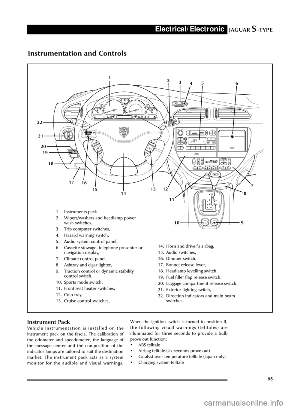
Instrumentation and Controls
1. Instruments pack
2. Wipers/washers and headlamp power
wash switches,
3. Trip computer switches,
4. Hazard warning switch,
5. Audio system control panel,
6. Cassette stowage, telephone presenter or
navigation display,
7. Climate control panel,
8. Ashtray and cigar lighter,
9. Traction control or dynamic stability
control switch,
10. Sports mode switch,
11. Front seat heater switches,
12. Coin tray,
13. Cruise control switches,
14. Horn and driverÕs airbag,
15. Audio switches,
16. Dimmer switch,
17. Bonnet release lever,
18. Headlamp levelling switch,
19. Fuel filler flap release switch,
20. Luggage compartment release switch,
21. Exterior lighting switch,
22. Direction indicators and main beam
switches,
1
7
8
9 10 11 12 13 19
16 17 18 20 21 22
142
3
45
6
15
Instrument Pack
Vehicle instrumentation is installed on the
instrument pack on the fascia. The calibration of
the odometer and speedometer, the language of
the message center and the composition of the
indicator lamps are tailored to suit the destination
market. The instrument pack acts as a system
monitor for the audible and visual warnings.When the ignition switch is turned to position II,
the following visual warnings (telltales) are
illuminated for three seconds to provide a bulb
prove out function:
¥ ABS telltale
¥ Airbag telltale (six seconds prove out)
¥ Catalyst over temperature telltale (Japan only)
¥ Charging system telltale
Page 101 of 133
JAGUARS-TYPEElectrical/Electronic
96
JOL.002
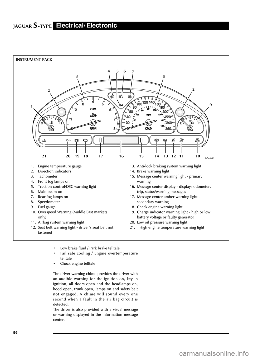
1. Engine temperature gauge
2. Direction indicators
3. Tachometer
4. Front fog lamps on
5. Traction control/DSC warning light
6. Main beam on
7. Rear fog lamps on
8. Speedometer
9. Fuel gauge
10. Overspeed Warning (Middle East markets
only)
11. Airbag system warning light
12. Seat belt warning light - driverÕs seat belt not
fastened13. Anti-lock braking system warning light
14. Brake warning light
15. Message center warning light - primary
warning
16. Message center display - displays odometer,
trip, status/warning messages
17. Message center amber warning light -
secondary warning
18. Check engine warning light
19. Charge indicator warning light - high or low
battery voltage or faulty generator
20. Low oil pressure warning light
21. High engine temperature warning light INSTRUMENT PACK
126 5 4
3
109 8 7
112
13 12 18 20 19 1416 15 17 21
¥ Low brake fluid / Park brake telltale
¥ Fail safe cooling / Engine overtemperature
telltale
¥ Check engine telltale
The driver warning chime provides the driver with
an audible warning for the ignition on, key in
ignition, all doors open and the headlamps on,
hood open, trunk open, lamps on and safety belt
not engaged. A chime will sound every one
second when a fault in the air bag circuit is
detected.
The driver is also provided with a visual message
or warning displayed in the information message
center.
Page 104 of 133
JAGUARS-TYPEElectrical/Electronic
99
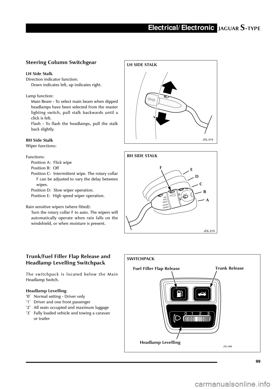
Steering Column Switchgear
LH Side Stalk
Direction indicator function:
Down indicates left, up indicates right.
Lamp function:
Main Beam - To select main beam when dipped
headlamps have been selected from the master
lighting switch, pull stalk backwards until a
click is felt.
Flash - To flash the headlamps, pull the stalk
back slightly.
RH Side Stalk
Wiper functions:
Functions:
Position A: Flick wipe
Position B: Off
Position C: Intermittent wipe. The rotary collar
F can be adjusted to vary the delay between
wipes.
Position D: Slow wiper operation.
Position E: High speed wiper operation.
Rain sensitive wipers (where fitted):
Turn the rotary collar F to auto. The wipers will
automatically operate when rain falls on the
windshield, or when moisture is present.
JOL.014
JOL.015
Trunk/Fuel Filler Flap Release and
Headlamp Levelling Switchpack
The switchpack is located below the Main
Headlamp Switch.
Headlamp Levelling
Ô0Õ Normal setting - Driver only
Ô1Õ Driver and one front passenger
Ô2Õ All seats occupied and maximum luggage
Ô3Õ Fully loaded vehicle and towing a caravan
or trailer
JOL.066
Trunk ReleaseFuel Filler Flap Release
Headlamp Levelling
LH SIDE STALK
RH SIDE STALK
A F
E
D
C
B
SWITCHPACK
Page 105 of 133
JAGUARS-TYPEElectrical/Electronic
100
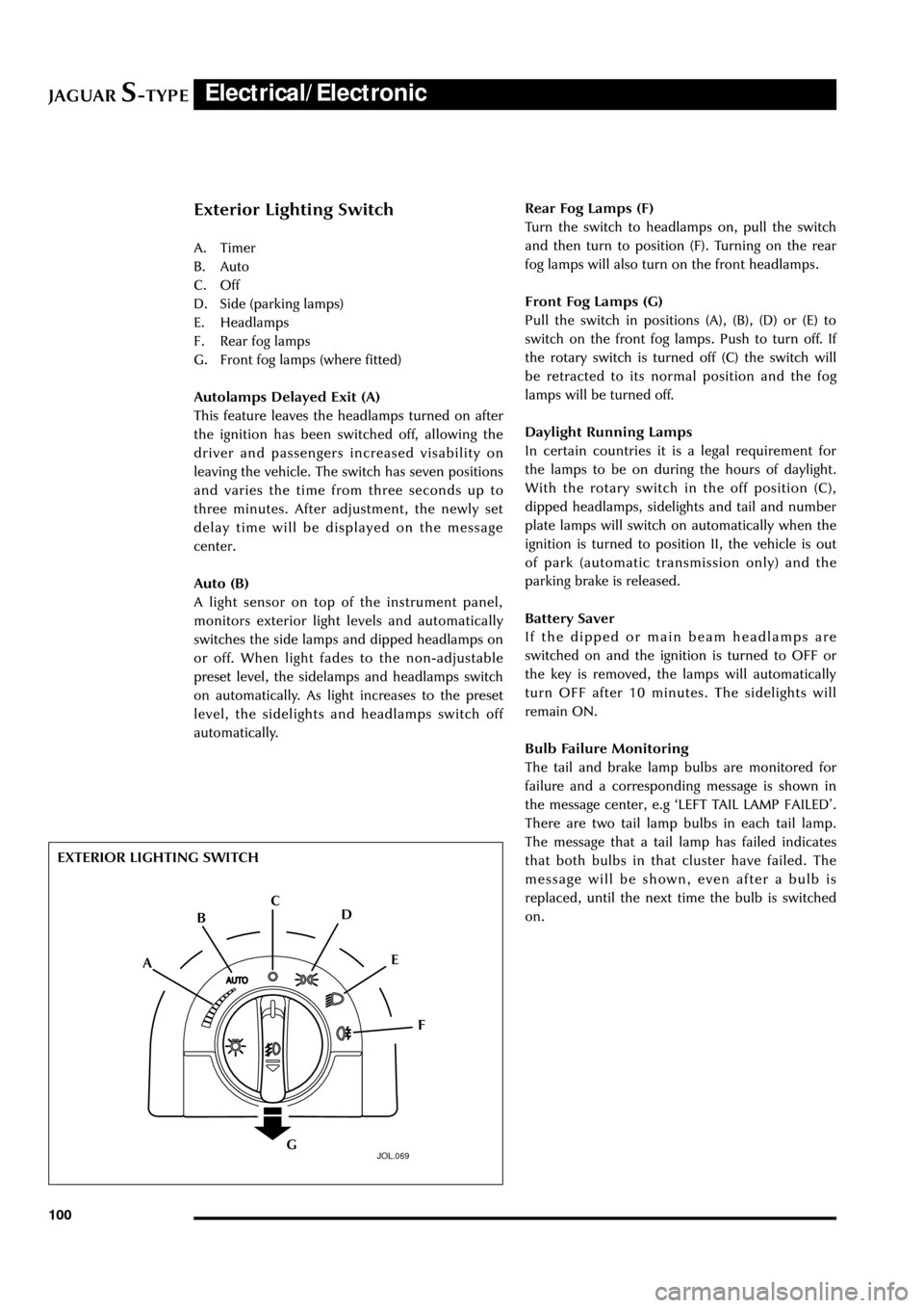
Exterior Lighting Switch
A. Timer
B. Auto
C. Off
D. Side (parking lamps)
E. Headlamps
F. Rear fog lamps
G. Front fog lamps (where fitted)
Autolamps Delayed Exit (A)
This feature leaves the headlamps turned on after
the ignition has been switched off, allowing the
driver and passengers increased visability on
leaving the vehicle. The switch has seven positions
and varies the time from three seconds up to
three minutes. After adjustment, the newly set
delay time will be displayed on the message
center.
Auto (B)
A light sensor on top of the instrument panel,
monitors exterior light levels and automatically
switches the side lamps and dipped headlamps on
or off. When light fades to the non-adjustable
preset level, the sidelamps and headlamps switch
on automatically. As light increases to the preset
level, the sidelights and headlamps switch off
automatically.Rear Fog Lamps (F)
Turn the switch to headlamps on, pull the switch
and then turn to position (F). Turning on the rear
fog lamps will also turn on the front headlamps.
Front Fog Lamps (G)
Pull the switch in positions (A), (B), (D) or (E) to
switch on the front fog lamps. Push to turn off. If
the rotary switch is turned off (C) the switch will
be retracted to its normal position and the fog
lamps will be turned off.
Daylight Running Lamps
In certain countries it is a legal requirement for
the lamps to be on during the hours of daylight.
With the rotary switch in the off position (C),
dipped headlamps, sidelights and tail and number
plate lamps will switch on automatically when the
ignition is turned to position II, the vehicle is out
of park (automatic transmission only) and the
parking brake is released.
Battery Saver
If the dipped or main beam headlamps are
switched on and the ignition is turned to OFF or
the key is removed, the lamps will automatically
turn OFF after 10 minutes. The sidelights will
remain ON.
Bulb Failure Monitoring
The tail and brake lamp bulbs are monitored for
failure and a corresponding message is shown in
the message center, e.g ÔLEFT TAIL LAMP FAILEDÕ.
There are two tail lamp bulbs in each tail lamp.
The message that a tail lamp has failed indicates
that both bulbs in that cluster have failed. The
message will be shown, even after a bulb is
replaced, until the next time the bulb is switched
on.
JOL.069
EXTERIOR LIGHTING SWITCH
A
F E D C
B
G