remote control JAGUAR S TYPE 2005 1.G Technical Guide Update
[x] Cancel search | Manufacturer: JAGUAR, Model Year: 2005, Model line: S TYPE, Model: JAGUAR S TYPE 2005 1.GPages: 133, PDF Size: 3.48 MB
Page 12 of 133

JAGUARS-TYPEIntroduction
7
TECHNOLOGY/COMMUNICATIONS and ENTERTAINMENT
Feature Applicability
Trip computerXin all markets
Jaguar sound systemXin all markets
Premium sound (including CD)Oin USA; NAin Canada; Xfor V8, Ofor V6 in Mexico
CD playerAfor USA and Mexico; Xfor Canada
Portable cellular phoneOin USA; Ain Canada and Mexico
Factory fit phone
Voice activated controlOin USA; NAin Canada and Mexico
Jaguar assist (VEMS)Oin USA; NAin Canada and Mexico
Navigation systemOin USA, NAin Canada and Mexico
COMFORT/CONVENIENCE and SAFETY
Feature Applicability
Climate controlXin all markets
Locking system (key and remote)Xin all markets
Security system (immobiliser, Xin USA, Canada and Mexico (no intrusion sensing)
alarm incl. intrusion sensing)Xin Europe
Side airbagsXin all markets
Illuminated sunvisorsXin all markets
Memory pack Xin USA, Canada and Mexico for V8 only; Ofor V6
Ofor entry 3.0 litre in all other markets
Xfor all other models/markets
NAin Japan
Headlamp levellingNAin USA, Canada, Mexico and Japan
Xin all other markets
Auto headlampsXin all markets (except Denmark, Norway and Sweden with
Daytime Running Lamps)
Daylight running lampsXin Denmark, Norway, Sweden and Canada
Front fog lampsXin USA, Canada and Mexico
Ofor 3.0 litre entry spec vehicles in UK, Ireland, Malta,
Xfor all other models/markets
Cruise controlNAin Japan
Ofor all entry level 3.0 litre
Xfor all other models/markets
Page 67 of 133

JAGUARS-TYPEChassis
62
J.211.257
STEERING COLUMN LOCK MODULE
Steering Column Lock (where fitted)
Lock Operation
The steering column lock module (SCLM) and
ignition key switch are separate assemblies and
activation of the lock is remotely controlled by the
instrument pack, GECM and RECM. The column is
unlocked on insertion of the ignition key and is
locked when the key is withdrawn.
The SCLM is mounted on top of the lower casting,
on the upper column assembly, by two shear
bolts. A locking bolt projects down from the SCLM
through a hole in the lower casting to engage into
a splined collar on the steering column. The SCLM
is an integrated non-serviceable assembly, housinga motor and worm drive for the locking bolt and
also an electronic printed circuit board. When
activated, the locking bolt is driven positively in
both the lock (down) and unlock (up) directions
and has a spring to help locate it into the trough
of the splined collar. When disengaging, the
locking bolt is driven upwards until it operates a
microswitch (within the SCLM) which causes the
motor to stop and also signals via the SCP bus that
the steering lock is off. To engage the lock, the
motor is energised for 350ms to lower the bolt.
System Control
The lock motor is powered by a switched 12V line
from the RECM and switched ground line from the
GECM, with both supplies being applied only
during lock operation. Initiation of motor drive
and direction and power supply switching is
controlled by the instrument pack via the SCP bus
when ignition key insertion or withdrawal is
detected. Identification is checked between the
SCLM and the other modules and the system will
not operate if, for example, a module has been
replaced and not re-programmed. System
diagnostics include defective modules and
incorrect module identification and also certain
SCLM faults, ie unconfimed lock or unlock
conditions and failed microswitch.
Steering Column Shrouds
The upper part of the column assembly is
enclosed by two plastic shrouds, upper and lower.
The steering column adjust switch, controlling tilt
and reach for the electrically powered steering
column assembly, is mounted on the side of the
lower shroud.
SCLM
Page 79 of 133

JAGUARS-TYPEElectrical/Electronic
74The SCP communication network will remain
operational even with severing of one of the bus
wires. Communications will also continue if one
of the bus wires is shorted to ground or battery
positive voltage (B+), or if some , but not all,
termination resistors are lost.
Unlike the SCP communication network, the
ISO 9141 communication network will not
function if the wire is shorted to ground or battery
positive voltage (B+). Also, if one of the modules
on the ISO 9141 network loses power or shorts
internally, communication to that module will fail.
Control Modules
The vehicle control module functions are
described briefly below (for further information
refer to the relevant sections throughout the
Guide).
Anti Lock Brake/Traction Control and
Dynamic Stability Control, Control Modules
The anti-lock brake control module is connected
to the SCP communication network. The module
comes in two forms. The first type is the standard
equipped anti-lock brake system (ABS) with
traction control (TC). It controls the brake
pressure to the four wheels to keep the vehicle
under control while braking.
The second type of ABS is optional and is called
dynamic stability control (DSC). This control
module adds yaw sensors to the package to help
in sensing a loss of vehicle control.
Audio Control Unit
The audio control unit is connected to the SCP
communication network and also to the audio
control protocol (ACP) communication network.
The audio control unit communicates with the
compact disc and the cellular phone transceiver.
Driver Door Control Module (DDCM)
DDCM is connected to the SCP communication
network. The module controls many functions
including power windows, driver mirror, power
locks, and keyless remote entry.Driver Seat Control Module (DSCM)
The DSCM is connected to the SCP
communication network. The DSCM is located
under the driver seat and controls the seat
positions. The module also communicates with the
DDCM to control the driver seat memory
functions.
Control Module Locations
Key to illustration on following page:
1.Anti-lock brake system/Traction control
system or Dynamic stability control
(ABS/TCCM or DSCCM)
(non-handed)
2.Throttle actuator control module (TACM)
(non-handed)
3.Powertrain control module (PCM) (handed)
4.Air conditioning control module (A/CCM)
(non-handed)
5.Restraint control module (RCM) (non-handed)
6.Sliding roof control module (SRCM)
(non-handed)
7.Passenger seat heater control module
(PSHCM) (non-handed)
8.Rear electronic control module (RECM)
(non-handed)
9.Vehicle information control module (VICM)
(Japan only)
10.Adaptive damping control module (ADCM)
(non-handed)
11.Parking aid control module (PACM)
(non-handed)
12.Navigation control module (NCM)
(non-handed)
13.Vehicle emergency control module (VECM)
(non-handed)
14.Voice-activated control module (VACM)
(non-handed)
15.Cellular telephone control module (CTCM)
(non-handed)
16.Driver seat heater control module (DSHCM)
(non-handed)
17.Driver seat control module (DSCM) (handed)
18.Driver door control module (DDCM)
(handed)
19.Instrument pack (handed)
20.General electronics control module (GECM)
(non-handed)
21.Steering column lock module (SCLM) (handed)
Page 81 of 133

JAGUARS-TYPEElectrical/Electronic
76Air Conditioning Control Module (A/CCM)
The A/CCM is connected to the SCP
communication network. The A/CCM controls
automatic climate functions that maintain the
vehicle at a constant temperature setting.
Instrument Pack
The instrument pack is connected to the SCP
communication network. The instrument pack
displays information received on the SCP
including speedometer, odometer, fuel, and
message center warnings. The instrument pack
also controls the passive anti-theft system (PATS).
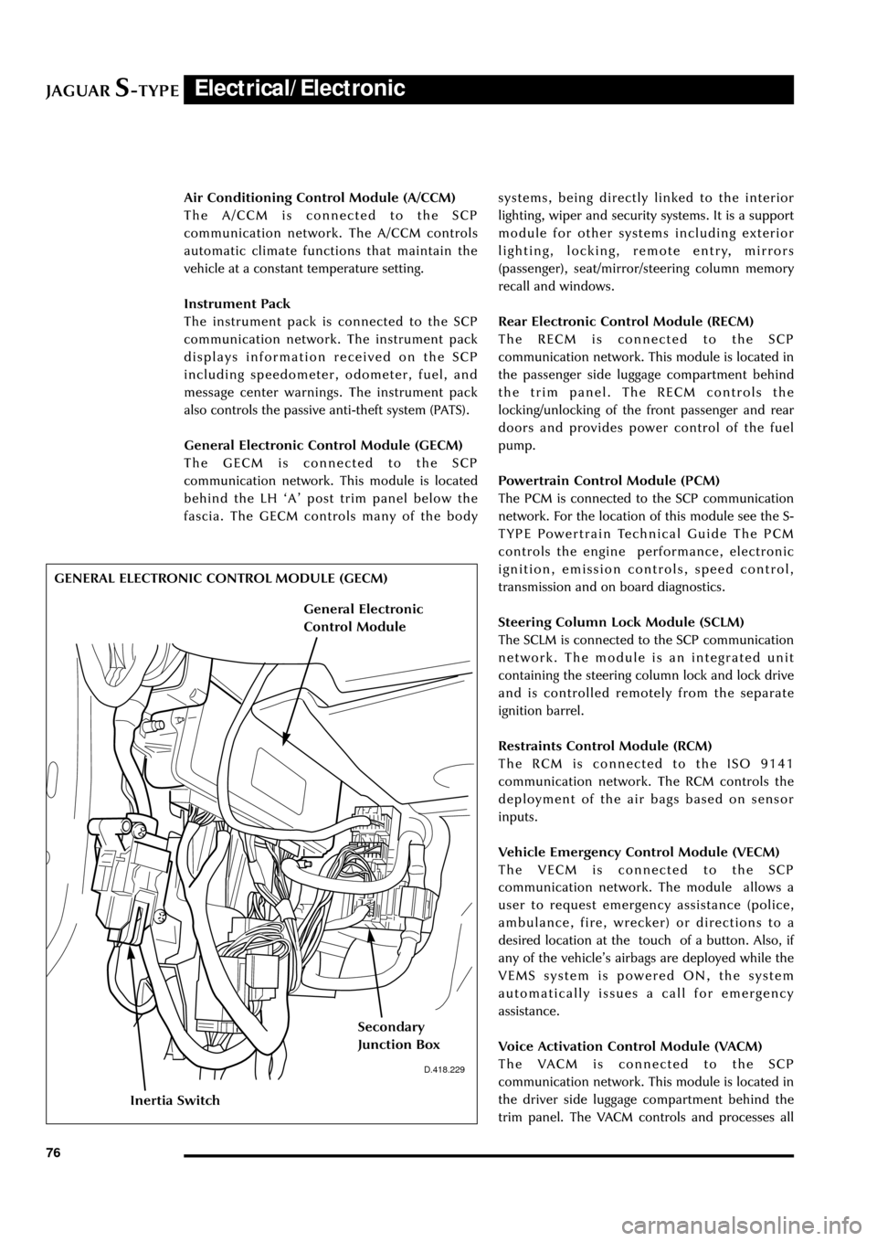
General Electronic Control Module (GECM)
The GECM is connected to the SCP
communication network. This module is located
behind the LH ÔAÕ post trim panel below the
fascia. The GECM controls many of the bodysystems, being directly linked to the interior
lighting, wiper and security systems. It is a support
module for other systems including exterior
lighting, locking, remote entry, mirrors
(passenger), seat/mirror/steering column memory
recall and windows.
Rear Electronic Control Module (RECM)
The RECM is connected to the SCP
communication network. This module is located in
the passenger side luggage compartment behind
the trim panel. The RECM controls the
locking/unlocking of the front passenger and rear
doors and provides power control of the fuel
pump.
Powertrain Control Module (PCM)
The PCM is connected to the SCP communication
network. For the location of this module see the S-
TYPE Powertrain Technical Guide The PCM
controls the engine performance, electronic
ignition, emission controls, speed control,
transmission and on board diagnostics.
Steering Column Lock Module (SCLM)
The SCLM is connected to the SCP communication
network. The module is an integrated unit
containing the steering column lock and lock drive
and is controlled remotely from the separate
ignition barrel.
Restraints Control Module (RCM)
The RCM is connected to the ISO 9141
communication network. The RCM controls the
deployment of the air bags based on sensor
inputs.
Vehicle Emergency Control Module (VECM)
The VECM is connected to the SCP
communication network. The module allows a
user to request emergency assistance (police,
ambulance, fire, wrecker) or directions to a
desired location at the touch of a button. Also, if
any of the vehicleÕs airbags are deployed while the
VEMS system is powered ON, the system
automatically issues a call for emergency
assistance.
Voice Activation Control Module (VACM)
The VACM is connected to the SCP
communication network. This module is located in
the driver side luggage compartment behind the
trim panel. The VACM controls and processes all
D.418.229
GENERAL ELECTRONIC CONTROL MODULE (GECM)
Inertia Switch
Secondary
Junction Box
General Electronic
Control Module
Page 113 of 133

JAGUARS-TYPEElectrical/Electronic
108
Security and Locking Systems
Introduction
The following security and locking features are
available but vary by market or options:
¥ Key barrel on driverÕs side only
¥ Encrypted engine immobilization by ignition
key transponder
¥ Radio frequency remote fob
¥ Central locking by key and remote fob
¥ Double locking (not in North America, Japan,
Taiwan)
¥ Drive away door locking
¥ Mechanical child locks on rear doors
¥ Perimeter alarm of doors, bonnet, trunk
¥ Intrusion sensing, ultrasonically sensed (not
in North America, Japan, Taiwan)
¥ Inclination (tilt) sensing (Dealer fit accessory)
¥ Panic alarm, fob operated (certain markets)
¥ Trunk lock isolate (valet lockout, see page
107) - North America only
¥ Electro/mechanical steering column lock
The following convenience features are included
either as standard or optional features:
¥ Remote fob operated driverÕs seat, door
mirrors and steering column memory recall
(two memories)
¥ Remote fob operated trunk lid release
¥ Key operated global close (sliding roof and all
windows)
¥ Key and fob remote-operated global open
(sliding roof and all windows)
¥ Trunk lid and fuel flap interior release buttons
¥ Trunk release button in trunk plinth
¥ Emergency key lock barrel under trunk plinth.
System Description
The security system is controlled by a driver door
control module (DDCM). When activated
unauthorized entry in to the vehicle is detected by
the courtesy lamp switches. When the alarm is
triggered, the system flashes the turn signal lamps
and sounds the alarm system horns.
The passive anti-theft system (PATS) is a feature to
prevent the vehicle being driven away by an
unauthorized person. The PATS system consists of
electronically coded keys, a transceiver and is
controlled by the Instrument Pack. When the
ignition is switched to position ÔIIÕ, the transceiver
energises the ignition key to read its electroniccode that is transmitted back. If the read code
equals a stored code in the control module, the
steering column is unlocked and the powertrain
control module (PCM) will let the engine start.
Otherwise, starting of the engine is disabled
(through the starter disable relay and the PCM).
The security indicator LED provides the driver
with the status of the PATS or security system. If
the security system is armed the light will flash
when the ignition is switched OFF. The PATS light
will illuminate when the key is inserted into the
ignition lock and turned to position ÔIIÕ. It will stay
illuminated until the system has carried out its test
on the key. If the system detects a fault, it will
flash the LED for 1 minute, and then flash out the
corresponding 2 digit fault code.
Security System Operating Components
Key to illustration on the following page:
1. Four button transmitter (North America/Rest
of the World)
2. Three button transmitter (Europe/Japan)
3. Trunk release switch
4. Trunk compartment actuator
5. Intrusion sensor
6. Door actuator
7. Driver door control module
8. Data link connector
9. General electronic control module
10. PATS transceiver module
11. Hood switch
12. Security LED
13. Horns
14. Security horn
15. Security sounder
16. Intrusion sensor
17. Rear electronic control module
Page 115 of 133

JAGUARS-TYPEElectrical/Electronic
110
JOL.145
Vehicle Locking and Unlocking
Door locks and handles
Only the driverÕs door has a key lock.
All doors and the luggage compartment can be
locked and unlocked using a key-ring transmitter.
Keys
Two black-headed keys (and one green-headed
key in the North American market) are supplied
with the vehicle. The key number is recorded on a
plastic tag which is attached to each key.
Each black-headed key will operate the ignition
switch and lock the doors, luggage compartment
and the glove box. The green-headed key is a valetkey which will not unlock a locked glove box or
locked trunk lid. The interior and exterior trunk
switches will not unlock the trunk lid when the
valet switch has been set.
An electronic device is fitted in the head of each
key which is programmed to the vehicle
electronics. When the key is placed in the ignition
switch the vehicle electronics recognize the
correct key and allow engine start. The engine
cannot be started with a key not programmed to
the vehicle electronic systems.
Up to eight keys can be used provided the Dealer
programs them all to the vehicle.
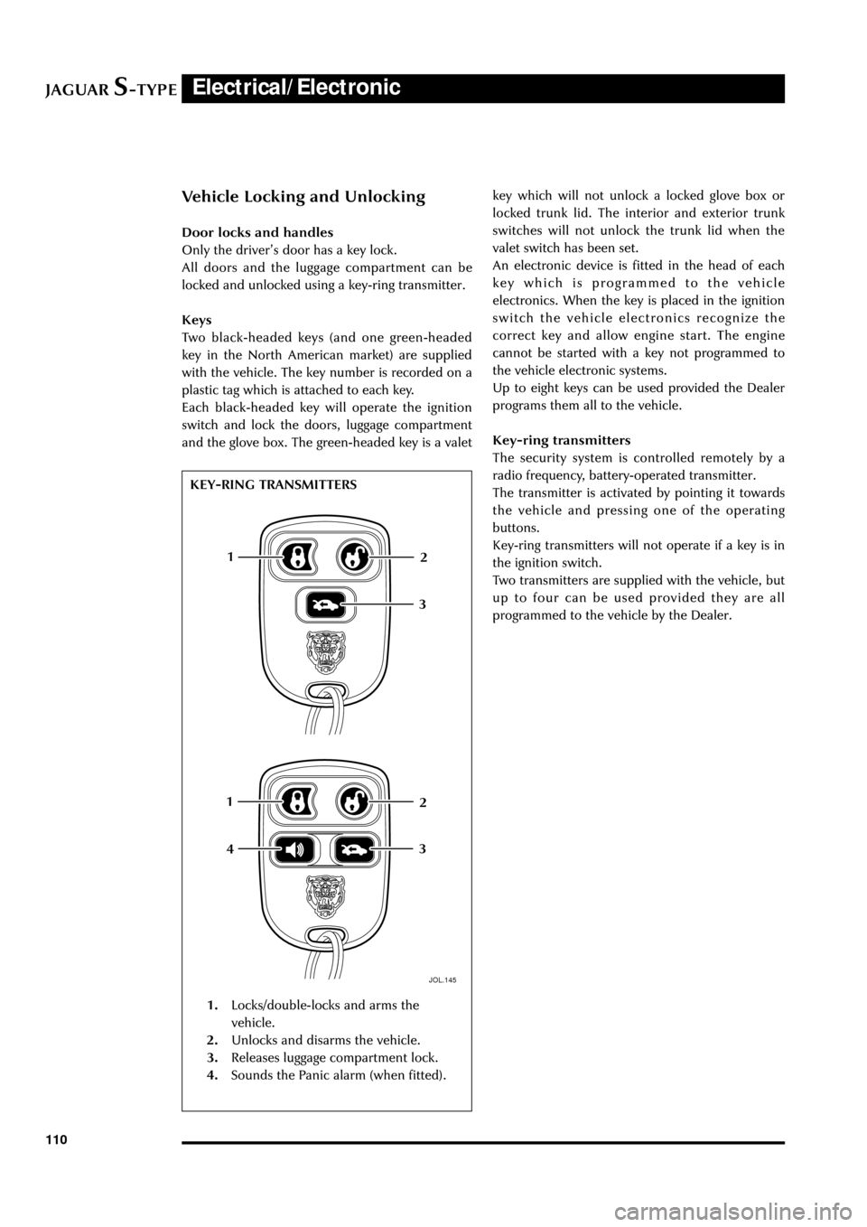
Key-ring transmitters
The security system is controlled remotely by a
radio frequency, battery-operated transmitter.
The transmitter is activated by pointing it towards
the vehicle and pressing one of the operating
buttons.
Key-ring transmitters will not operate if a key is in
the ignition switch.
Two transmitters are supplied with the vehicle, but
up to four can be used provided they are all
programmed to the vehicle by the Dealer.
1
12
2
3
3
4
1.Locks/double-locks and arms the
vehicle.
2.Unlocks and disarms the vehicle.
3.Releases luggage compartment lock.
4.Sounds the Panic alarm (when fitted). KEY-RING TRANSMITTERS
Page 116 of 133

JAGUARS-TYPEElectrical/Electronic
111 Steering Column Lock
The steering column lock is remote from the
ignition switch and controlled electronically.
When the ignition key is removed from the
ignition switch the steering column lock is
engaged. The lock is disengaged when the key is
placed in the ignition switch.
The lock can be clearly heard as it engages and
disengages.
In rare circumstances it may be necessary to
gently turn the steering wheel from side to side to
release the steering column lock.
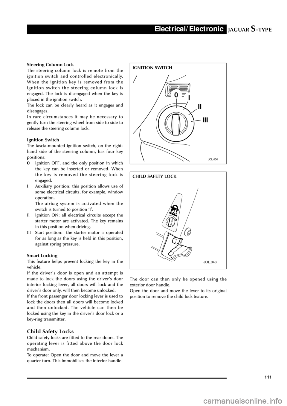
Ignition Switch
The fascia-mounted ignition switch, on the right-
hand side of the steering column, has four key
positions:
0Ignition OFF, and the only position in which
the key can be inserted or removed. When
the key is removed the steering lock is
engaged.
IAuxiliary position: this position allows use of
some electrical circuits, for example, window
operation.
The airbag system is activated when the
switch is turned to position ÔIÕ.
II Ignition ON: all electrical circuits except the
starter motor are activated. The key remains
in this position when driving.
III Start position: the starter motor is operated
for as long as the key is held in this position,
against spring pressure.
Smart Locking
This feature helps prevent locking the key in the
vehicle.
If the driverÕs door is open and an attempt is
made to lock the doors using the driverÕs door
interior locking lever, all doors will lock and the
driverÕs door only, will then become unlocked.
If the front passenger door locking lever is used to
lock the doors then all doors will become locked
and then unlocked. The vehicle can then be
locked using the key in the driverÕs door lock or a
key-ring transmitter.
Child Safety Locks
Child safety locks are fitted to the rear doors. The
operating lever is fitted above the door lock
mechanism.
To operate: Open the door and move the lever a
quarter turn. This immobilises the interior handle.
JOL.050
IGNITION SWITCH
JOL.048
The door can then only be opened using the
exterior door handle.
Open the door and move the lever to its original
position to remove the child lock feature.CHILD SAFETY LOCK
Page 128 of 133

JAGUARS-TYPEElectrical/Electronic
123
JOL.136
Quarter-turn Fastener
CD Load Cover
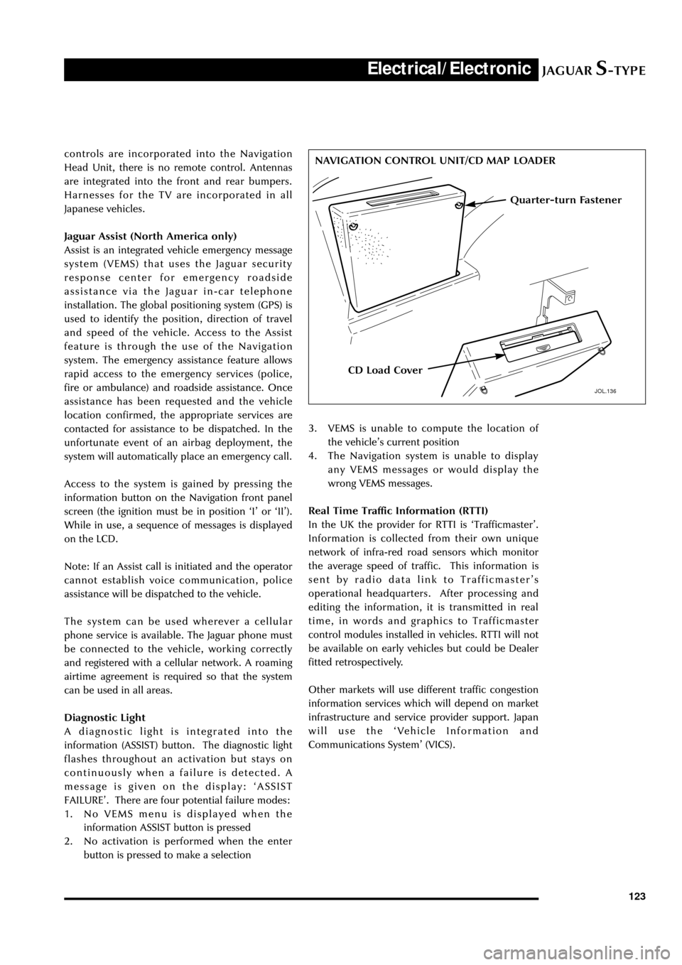
NAVIGATION CONTROL UNIT/CD MAP LOADER controls are incorporated into the Navigation
Head Unit, there is no remote control. Antennas
are integrated into the front and rear bumpers.
Harnesses for the TV are incorporated in all
Japanese vehicles.
Jaguar Assist (North America only)
Assist is an integrated vehicle emergency message
system (VEMS) that uses the Jaguar security
response center for emergency roadside
assistance via the Jaguar in-car telephone
installation. The global positioning system (GPS) is
used to identify the position, direction of travel
and speed of the vehicle. Access to the Assist
feature is through the use of the Navigation
system. The emergency assistance feature allows
rapid access to the emergency services (police,
fire or ambulance) and roadside assistance. Once
assistance has been requested and the vehicle
location confirmed, the appropriate services are
contacted for assistance to be dispatched. In the
unfortunate event of an airbag deployment, the
system will automatically place an emergency call.
Access to the system is gained by pressing the
information button on the Navigation front panel
screen (the ignition must be in position ÔIÕ or ÔIIÕ).
While in use, a sequence of messages is displayed
on the LCD.
Note: If an Assist call is initiated and the operator
cannot establish voice communication, police
assistance will be dispatched to the vehicle.
The system can be used wherever a cellular
phone service is available. The Jaguar phone must
be connected to the vehicle, working correctly
and registered with a cellular network. A roaming
airtime agreement is required so that the system
can be used in all areas.
Diagnostic Light
A diagnostic light is integrated into the
information (ASSIST) button. The diagnostic light
flashes throughout an activation but stays on
continuously when a failure is detected. A
message is given on the display: ÔASSIST
FAILUREÕ. There are four potential failure modes:
1. No VEMS menu is displayed when the
information ASSIST button is pressed
2. No activation is performed when the enter
button is pressed to make a selection3. VEMS is unable to compute the location of
the vehicleÕs current position
4. The Navigation system is unable to display
any VEMS messages or would display the
wrong VEMS messages.
Real Time Traffic Information (RTTI)
In the UK the provider for RTTI is ÔTrafficmasterÕ.
Information is collected from their own unique
network of infra-red road sensors which monitor
the average speed of traffic. This information is
sent by radio data link to TrafficmasterÕs
operational headquarters. After processing and
editing the information, it is transmitted in real
time, in words and graphics to Trafficmaster
control modules installed in vehicles. RTTI will not
be available on early vehicles but could be Dealer
fitted retrospectively.
Other markets will use different traffic congestion
information services which will depend on market
infrastructure and service provider support. Japan
will use the ÔVehicle Information and
Communications SystemÕ (VICS).