Connector JAGUAR X308 1998 2.G Workshop Manual
[x] Cancel search | Manufacturer: JAGUAR, Model Year: 1998, Model line: X308, Model: JAGUAR X308 1998 2.GPages: 2490, PDF Size: 69.81 MB
Page 1239 of 2490

E
lectronic Engine Controls - Cr
ankshaft Position (CKP) Sensor
Re
moval and Installation
Remov
al
1.
Disc
onnect battery ground cable (IMPORTANT, see SRO
86.15.19 for further information).
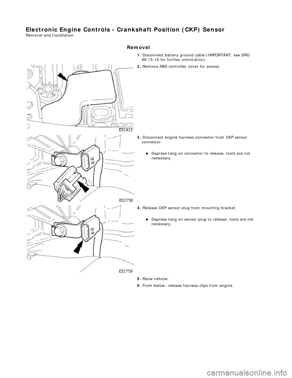
2. R
emove ABS controller cover for access.
3. Di
sconnect engine harness connector from CKP sensor
connector.
пЃ¬De
press tang on connector to release, tools are not
necessary.
4. Re
lease CKP sensor plug from mounting bracket.
пЃ¬Depress tan
g on sensor plug
to release, tools are not
necessary.
5. Raise vehicle.
6. From below: release harn ess clips from engine.
Page 1241 of 2490

E
lectronic Engine Controls - Engine
Control Module (ECM) Adaptation
Gen
eral Procedures
When to car
ry out adaptations
DTCs P1000/P1111 Conditions for adaptation
Fuelling Adaptations Drive Cycle
•
NOTE: Make sure the engine is at normal operating
temperature. (75В°C, 167В°F) 1.
Whenever the battery is disconnected, the Engine Control
Module (ECM) adaptations are reset to a "green" ECM
condition. In this condition, certain functions of the ECM are
inhibited, and the ECM must "r elearn" these functions. To
enable the ECM to do this, the vehicle will have to perform
some maneuvres which it may, or may not, do during a normal
road test. The routine in this pr ocedure should be carried out at
Pre-Delivery Inspection, and after any emissions related
rectification work involving the disconnection of the battery.
2. When the DTCs relating to a rectified concern are cleared,
P1000 (system checks not complete since last memory clear)
will be flagged. This DTC does no t indicate a failure, just that
diagnostic drive cycles need to be performed. The vehicle's on-
board diagnostic system will confirm that all the diagnostic
drive cycles are complete by flagging P1111, (system checks
complete since last memory clear)
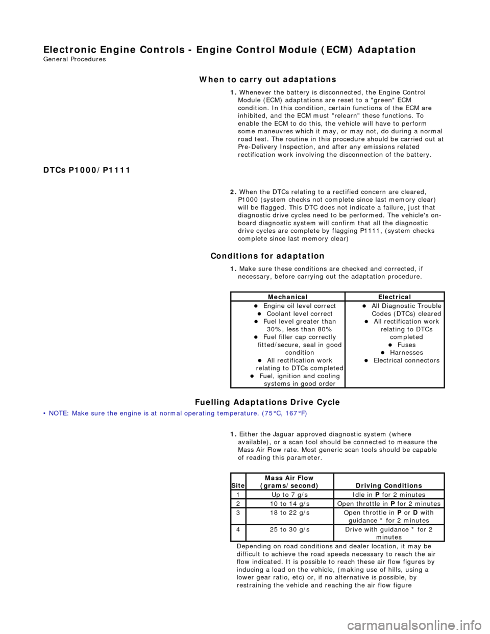
1. Make sure these conditions are checked and corrected, if
necessary, before carrying ou t the adaptation procedure.
MechanicalElectrical
пЃ¬Engi
ne oil level correct
пЃ¬Coo
lant level correct
пЃ¬F
uel level greater than
30%, less than 80%
пЃ¬F
uel filler cap correctly
fitted/secure, seal in good condition
пЃ¬Al
l rectification work
relating to DTCs completed
пЃ¬F
uel, ignition and cooling
systems in good order
пЃ¬Al
l Diagnostic Trouble
Codes (DTCs) cleared
пЃ¬Al
l rectification work
relating to DTCs completed
пЃ¬F
uses
пЃ¬Harnes
ses
пЃ¬E
lectrical connectors
1.
Either
the Jaguar approved diagnostic system (where
available), or a scan tool should be connected to measure the
Mass Air Flow rate. Most generi c scan tools should be capable
of reading this parameter.
Depending on road conditions and dealer location, it may be
difficult to achieve the road sp eeds necessary to reach the air
flow indicated. It is possible to reach these air flow figures by
inducing a load on the vehicle, (making use of hills, using a
lower gear ratio, etc) or, if no alternative is possible, by
restraining the vehicle and re aching the air flow figure
Si
te
Mass Air Flow
(gra
ms/second)
D
riving Conditions
1Up t
o 7 g/s
Idle
in
P for 2 minutes
21
0 to 14 g/s
O
pen throttle in
P for 2 minutes
31
8 to 22 g/s
O
pen throttle in
P or D with
guidance * for 2 minutes
42
5 to 30 g/s
D
rive with guidance * for 2
minutes
Page 1245 of 2490

E
lectronic Engine Controls - Engine Control Module (ECM)
Re
moval and Installation
Remov
al
Installation
1.
Disc
onnect battery ground cable (IMPORTANT, see SRO
86.15.19 for further information).
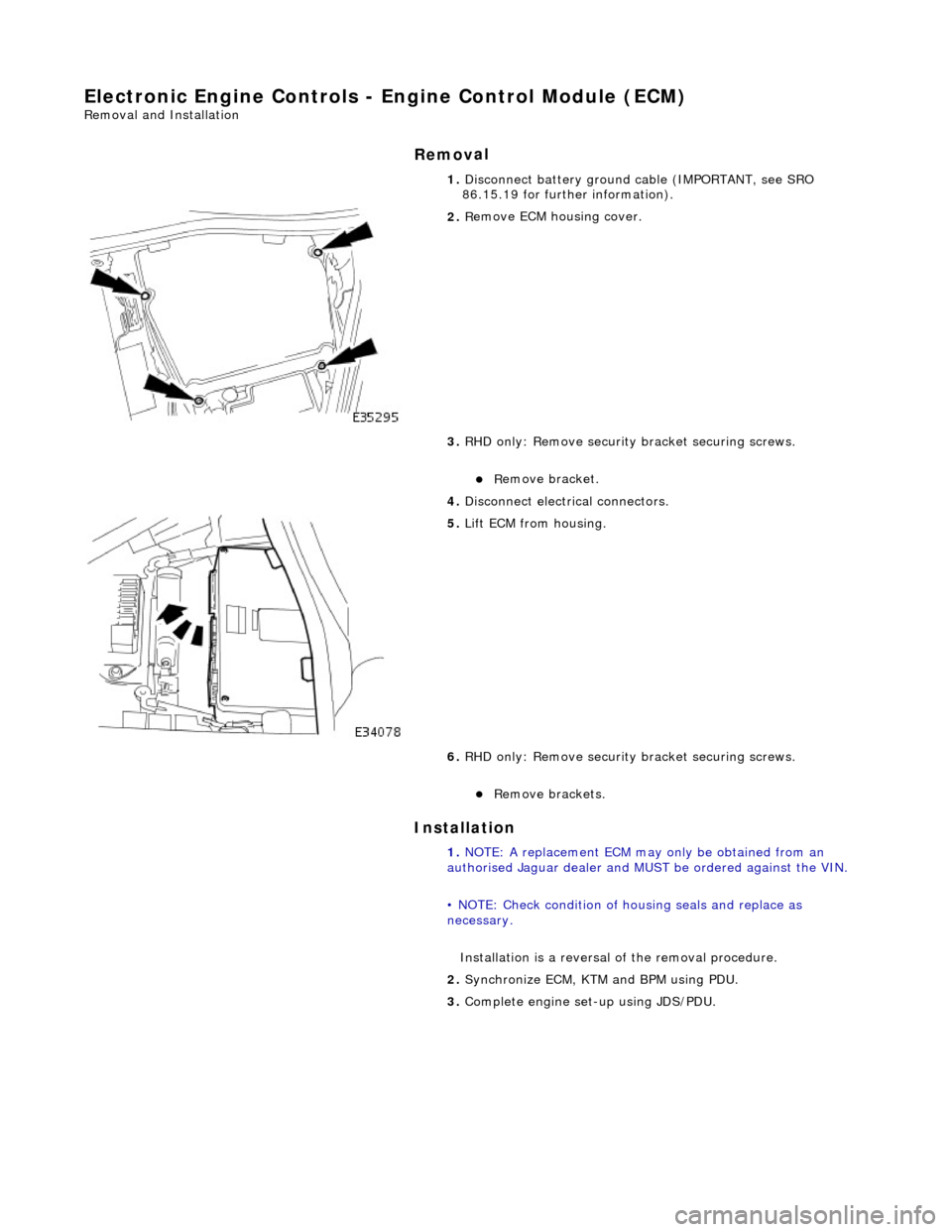
2. R
emove ECM housing cover.
3. RHD only: Remove security bracket securing screws.
пЃ¬R
emove bracket.
4. Disconnect electrical connectors.
5. Li
ft ECM from housing.
6. RHD only: Remove security bracket securing screws.
пЃ¬R
emove brackets.
1. NOTE: A replacement ECM may only be obtained from an
authorised Jaguar dealer and MU ST be ordered against the VIN.
• NOTE: Check condition of ho using seals and replace as
necessary.
Installation is a reversal of the removal procedure.
2. Synchronize ECM, KTM and BPM using PDU.
3. Complete engine set- up using JDS/PDU.
Page 1251 of 2490

E
lectronic Engine Controls - Inta
ke Air Temperature (IAT) Sensor
Re
moval and Installation
Remov
al
Installation
1.
Di
sconnect sensor connector at
rear of bank 1 charge air
cooler.
2. Re
move sensor.
пЃ¬Re
move sensor using a deep socket.
пЃ¬Discard sealin
g washer.
1. Installation is a reversal of the removal procedure.
Page 1252 of 2490

El
ectronic Engine Controls - Knock Se
nsor (KS) LH4.0L NA V8 - AJ27/3.2L
NA V8 - AJ26
Re mo
val and Installation
Remova
l
Installation
1.
Disc onne
ct battery ground cable (IMPORTANT, see SRO
86.15.19 for further information).
2. Remove for access, appropriat e engine cover; refer to
12.30.06.
3. NO TE
: Bank 1 shown.
Disconnect knock sensor conne ctor from mounting bracket.
4. Disc
onnect connector.
5. NO TE
: Bank 1 shown.
Using special tools, crowfoot and extension, remove knock
sensor.
1. Installation is a reversal of the removal procedure.
2. Tighten sensor to 31 - 41 Nm.
Page 1253 of 2490

E
lectronic Engine Controls - Knock
Sensor (KS) LH4.0L SC V8 - AJ26
Re
moval and Installation
Remov
al
Installation
1.
R
emove supercharger; refer to 18.50.15.
2. Remove knock sensor from engine.
пЃ¬De
tach connector and disconnect.
пЃ¬R
emove knock sensor.
1. Installation is a reversal of the removal procedure.
2. Tighten sensor to 31 - 41 Nm.
Page 1254 of 2490

El
ectronic Engine Controls - Knock Se
nsor (KS) RH4.0L NA V8 - AJ27/3.2L
NA V8 - AJ26
Re mo
val and Installation
Remova
l
Installation
1.
Disc onne
ct battery ground cable (IMPORTANT, see SRO
86.15.19 for further information).
2. Remove for access, appropriat e engine cover; refer to
12.30.06.
3. Disc onne
ct knock sensor conne
ctor from mounting bracket.
4. Disc
onnect connector.
5. Using speci a
l tools, crowfoot
and extension, remove knock
sensor.
1. Installation is a reversal of the removal procedure.
2. Tighten sensor to 31 - 41 Nm.
Page 1255 of 2490

E
lectronic Engine Controls - Knock
Sensor (KS) RH4.0L SC V8 - AJ26
Re
moval and Installation
Remov
al
Installation
1.
R
emove supercharger; refer to 18.50.15.
2. Remove knock sensor from engine.
пЃ¬De
tach connector and disconnect.
пЃ¬R
emove knock sensor.
1. Installation is a reversal of the removal procedure.
2. Tighten sensor to 31 - 41 Nm.
Page 1256 of 2490

El
ectronic Engine Controls -
Mass Air Flow (MAF) Sensor
Remo
val and Installation
Remov
a
l
1.
Disc onne
ct battery ground cable (IMPORTANT, see SRO
86.15.19 for further information).
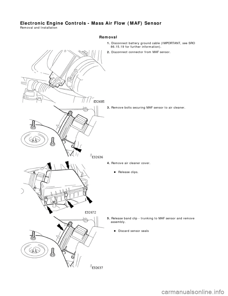
2. Disc
onnect connector from MAF sensor.
3. Re
move bolts securing MAF sensor to air cleaner.
4. Re
move air cleaner cover.
пЃ¬Re
lea
se clips.
5. Re
lease band clip - trunking to MAF sensor and remove
assembly.
пЃ¬Di sc
ard sensor seals
Page 1258 of 2490

El
ectronic Engine Controls - Variable
Camshaft Timing (VCT) Oil Control
Solenoid
Re mo
val and Installation
Remova
l
1.
Op
en the engine compartment and fit paintwork protection
sheets.
2. Disc
onnect the batt
ery ground cable.
пЃ¬Re
move the battery cover.
3. Disc
onnect the VVT solenoid connector.
4. Re
move the two bolts which secure the VVT solenoid to the
timing cover.
5. Pull the VVT solenoid clear and discard the O-ring.