ECM JAGUAR X308 1998 2.G Owner's Manual
[x] Cancel search | Manufacturer: JAGUAR, Model Year: 1998, Model line: X308, Model: JAGUAR X308 1998 2.GPages: 2490, PDF Size: 69.81 MB
Page 540 of 2490
Pinpoint test C: P1396
VVT solenoid malfunction
W
i
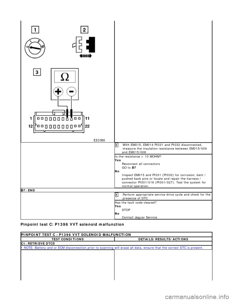
th EM015, EM014 PI031 and PI032 disconnected,
measure the insulation resistance between EM015/009
and EM015/008
1
I s
the resistance > 10 MOHM?
Yes Reconnect all connectors
GO to B7
No Inspect EM015 and PI031 (PI032) for corrosion, bent /
pushed back pins or locate and repair the harness /
connector PI001/016 (PI001/027). Test the system for
normal operation.
B7: EN
D
Perform
a
ppropriate service drive cycle and check for the
presence of DTC
1
Has th
e fault code cleared?
Yes STOP
No Contact Jaguar Service
PINPOINT TES
T C : P1396 VVT SOLENOID MALFUNCTION
T
E
ST CONDITIONS
D
E
TAILS/RESULTS/ACTIONS
C1
: RETRIEVE DTC
S
•
NOTE
: Battery and or ECM disconnection prior to scanning wi
ll erase all data, ensure that the correct DTC is present.
Page 930 of 2490
Whe r
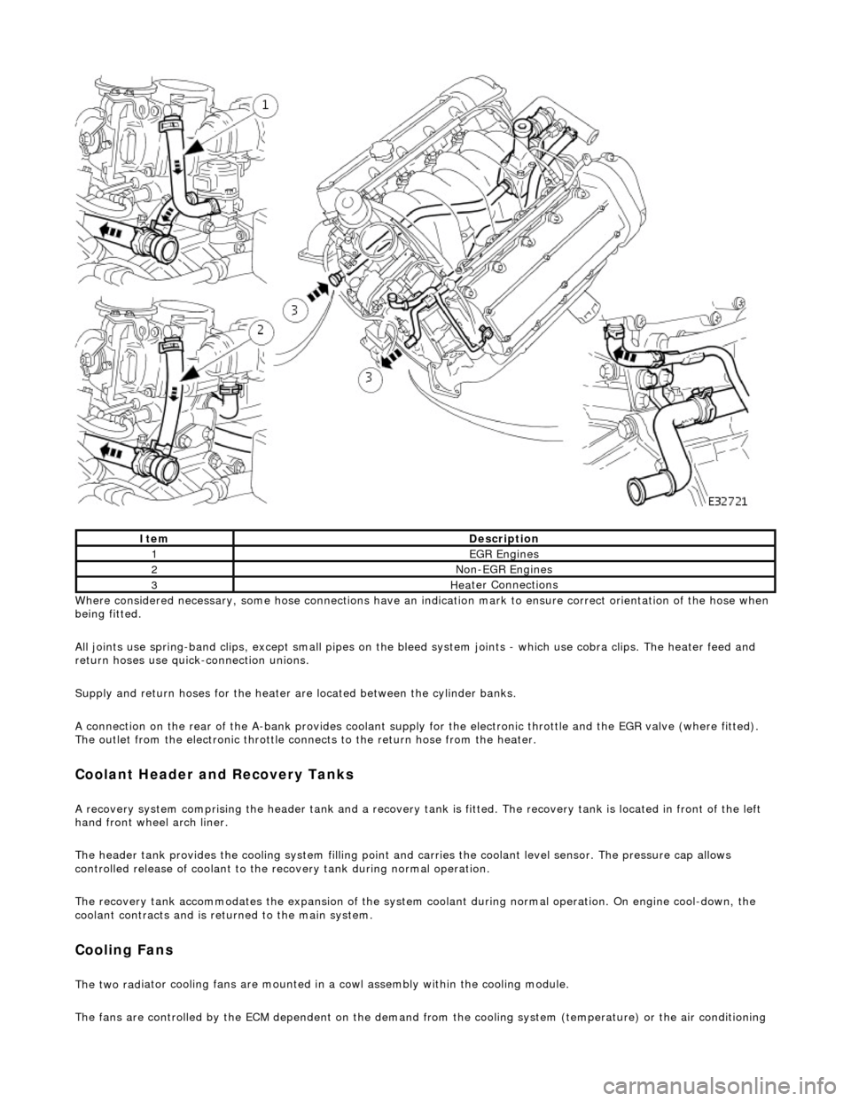
e considered necessary, some hose conn
ections have an indication mark to ensure correct orientation of the hose when
being fitted.
All joints use spring-band clips, except small pipes on the bleed system joints - which use cobra clips. The heater feed and
return hoses use quick-connection unions.
Supply and return hoses for the heater are located between the cylinder banks.
A connection on the rear of the A-bank provides coolant supply for the electronic throttle and the EGR valve (where fitted).
The outlet from the electronic throttle connects to the return hose from the heater.
Cool
ant Header and Recovery Tanks
A recovery system comp
rising the header tank
and a recovery tank is fitted. The recove ry tank is located in front of the left
hand front wheel arch liner.
The header tank provides the cooling system filling point and carries the coolant level sensor. The pressure cap allows
controlled release of coolant to the re covery tank during normal operation.
The recovery tank accommodates the expansion of the system coolant during normal operation. On engine cool-down, the
coolant contracts and is returned to the main system.
Coo lin
g Fans
The two
rad
iator cooling fans are mounted in
a cowl assembly within the cooling module.
The fans are controlled by the ECM dependent on the demand fr om the cooling system (temperature) or the air conditioning
ItemDescrip
tion
1EGR
E
ngines
2Non
-
EGR Engines
3Hea
ter Connections
Page 931 of 2490
s
ystem (pressure).
Outputs from the ECM control the radiator fans control module, located behind the left hand side of the bumper, to operate
the fans in the series mode (slow), paralle l mode (Fast) or Off modes. Hysteresis in the temperature and pressure switching
values prevents 'hun ting' between modes.
Under hot operating conditions, the fans may continue to operat e for some time after the engine has been switched off, but
will stop automatically when the coolant te mperature has been sufficiently reduced.
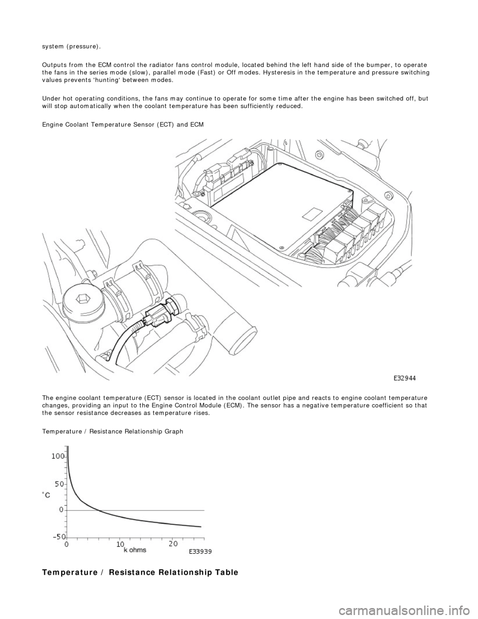
Engine Coolant Temperature Sensor (ECT) and ECM
The engine coolant temperature (ECT) sensor is located in the coolant outlet pipe and reacts to engine coolant temperature
changes, providing an input to the Engine Control Module (ECM). The sensor has a negative te mperature coefficient so that
the sensor resistance decrea ses as temperature rises.
Temperature / Resistance Relationship Graph
T
emperature / Resistance
Relationship Table
Page 935 of 2490
Pinpoint test
A: P0116, P0125
Connector
loose or corroded
*
D
TC P0118 ECT circuit high input
Sensor short
Harness open circui
t
Harness short
Connector loose or corroded
*
*
*
*
GO to Pinpoint
Test C
*
D
TC P1474 Intercooler coolant pump relay malfunction
Intercooler pump relay
failure
Intercooler pump relay to ECM drive circuit
fault Intercooler pump relay coil ground circuit
fault Harness fault
Connector loose or corroded
Connector pins(s) bent or tracking between
connections ECM power supply fault
*
*
*
*
*
*
*
GO to Pinpoint
Test D
*
P
INPOINT TEST A : P0116, P0125
T
EST CONDITIONS
D
ETAILS/RESULTS/ACTIONS
A1
: RETRIEVE DTCS
•
NOTE: Battery and or ECM disconnection prior to scanning wi
ll erase all data, ensure that the correct DTC is present.
Conne
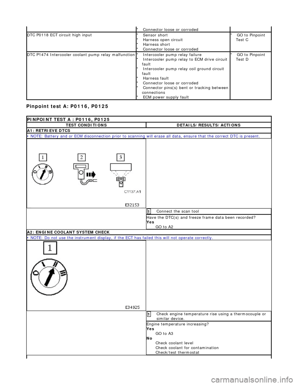
ct the scan tool
1
Have the DTC(s) and fr
eeze
frame data been recorded?
Yes GO to A2
A2: ENGINE
COOLANT SYSTEM CHECK
•
NOTE: Do not use the instrument display, if th
e ECT has failed this will not operate correctly.
Chec
k engine temperature rise using a thermocouple or
similar device.
1
Engine
temperature increasing?
Yes GO to A3
No Check coolant level
Check coolant for contamination
Check/test thermostat
Page 939 of 2490
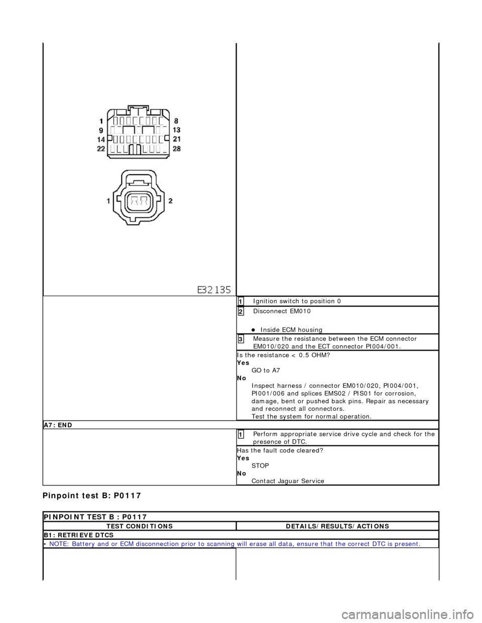
Pinpoint test
B: P0117
I
gnition switch to position 0
1
Di
sconnect EM010
Inside E
CM housing
2
Meas
ure the resistance between the ECM connector
EM010/020 and the ECT connector PI004/001.
3
I
s the resistance < 0.5 OHM?
Yes GO to A7
No Inspect harness / connector EM010/020, PI004/001,
PI001/006 and splices EMS02 / PIS01 for corrosion,
damage, bent or pushed back pins. Repair as necessary
and reconnect all connectors.
Test the system for normal operation.
A7
: END
Perform
appropriate service drive cycle and check for the
presence of DTC.
1
Has
the fault code cleared?
Yes STOP
No Contact Jaguar Service
P
INPOINT TEST B : P0117
T
EST CONDITIONS
D
ETAILS/RESULTS/ACTIONS
B1
: RETRIEVE DTCS
•
NOTE: Battery and or ECM disconnection prior to scanning wi
ll erase all data, ensure that the correct DTC is present.
Page 941 of 2490
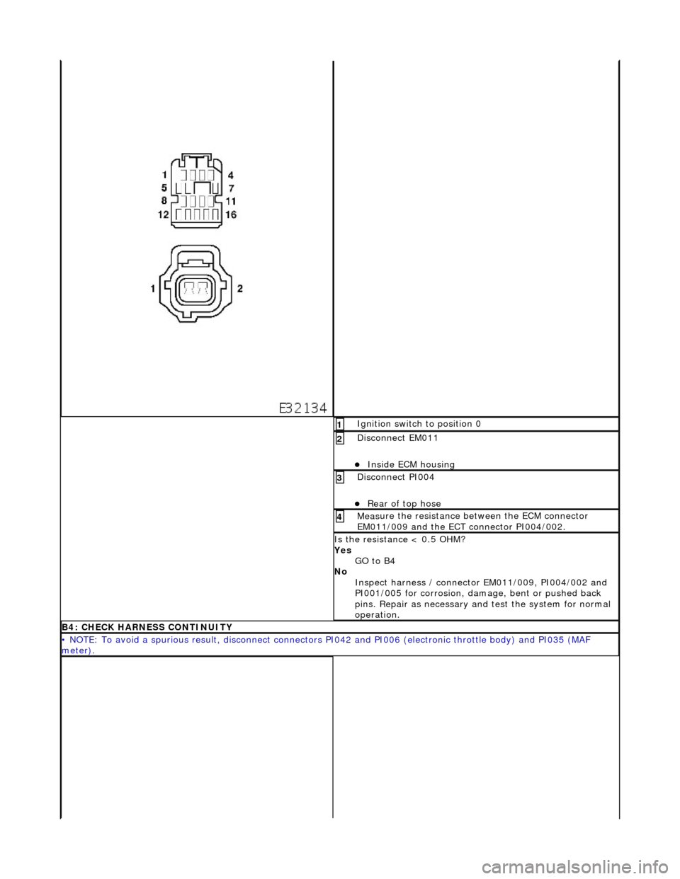
I
gnition switch to position 0
1
Di
sconnect EM011
Inside E
CM housing
2
D
isconnect PI004
Re
ar of top hose
3
Meas
ure the resistance between the ECM connector
EM011/009 and the ECT connector PI004/002.
4
I
s the resistance < 0.5 OHM?
Yes GO to B4
No Inspect harness / connector EM011/009, PI004/002 and
PI001/005 for corrosion, damage , bent or pushed back
pins. Repair as necessary and test the system for normal
operation.
B4: CHECK
HARNESS CONTINUITY
•
NOTE: To avoid a spurious result, disconnect connectors PI042 and PI006 (electronic throttle body) and PI035 (MAF
meter).
Page 942 of 2490
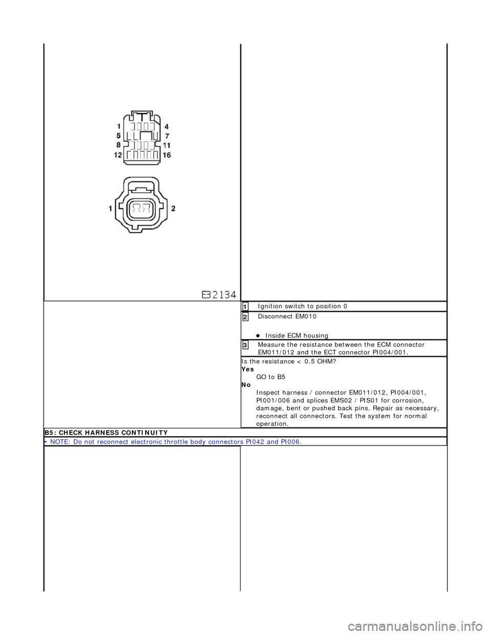
Ig
nition switch to position 0
1
Di
sc
onnect EM010
Inside E
C
M housing
2
Meas
ure t
he resistance between the ECM connector
EM011/012 and the ECT connector PI004/001.
3
I s
the resistance < 0.5 OHM?
Yes GO to B5
No Inspect harness / connector EM011/012, PI004/001,
PI001/006 and splices EMS02 / PIS01 for corrosion,
damage, bent or pushed back pins. Repair as necessary,
reconnect all connectors. Te st the system for normal
operation.
B5: CHECK HARNESS
CONTINUITY
•
NOTE
: Do not reconnect electronic thro
ttle body connectors PI042 and PI006.
Page 943 of 2490

I
gnition switch to position 0
1
Di
sconnect EM010
Inside E
CM housing
2
Meas
ure the resistance between the ECM connector
EM010/020 and the ECT connector PI004/001.
3
I
s the resistance < 0.5 OHM?
Yes GO to B6
No Inspect harness / connector EM010/020, PI004/001,
PI001/006 and splices EMS02 / PIS01 for corrosion,
damage, bent or pushed back pins. Repair as required and
reconnect all connectors. Te st the system for normal
operation.
B6:
CHECK FOR SHORT TO B+
Page 944 of 2490
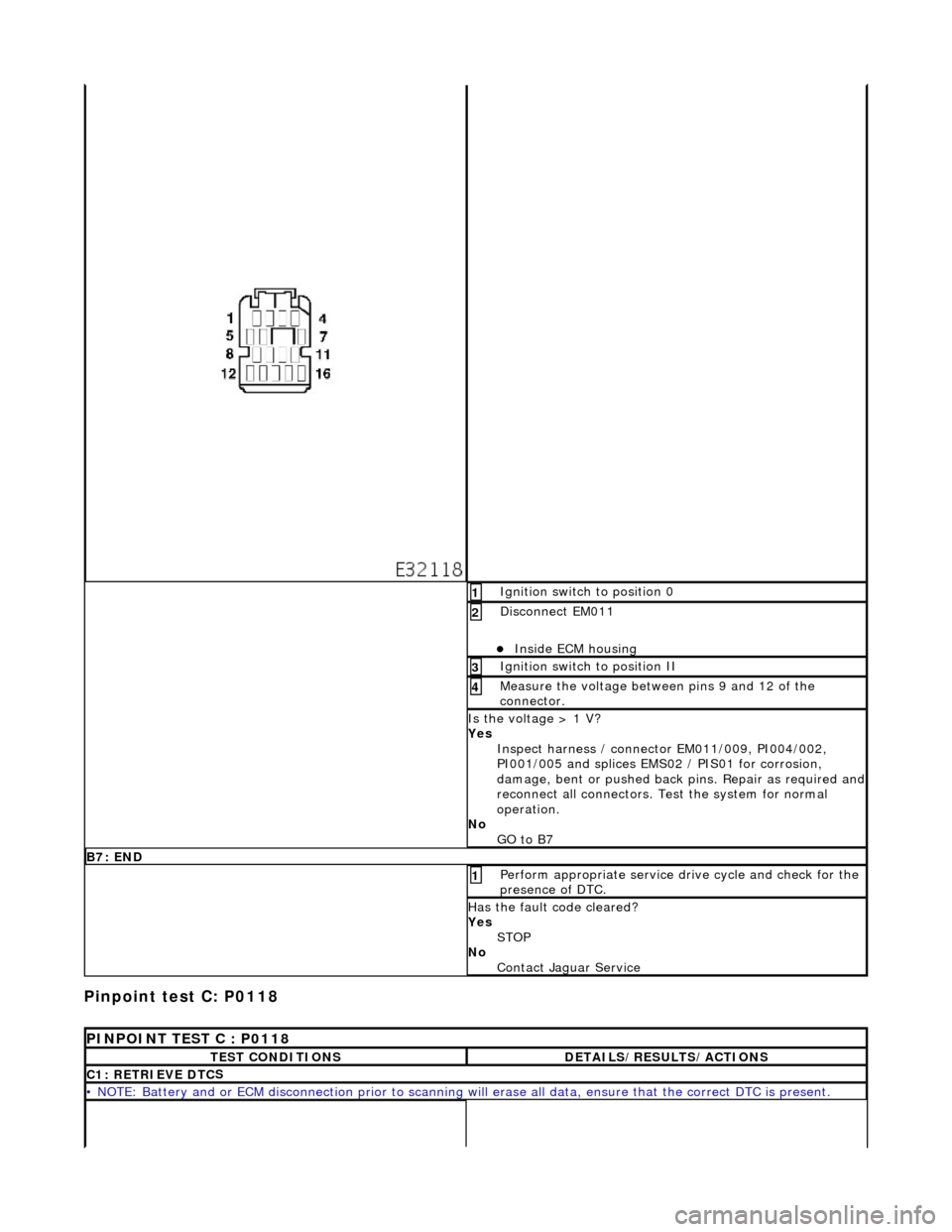
Pinpoint test C: P0118
I
g
nition switch to position 0
1
Di
sc
onnect EM011
Inside E
C
M housing
2
I
g
nition switch to position II
3
Measure the
voltage betwee n pin
s 9 and 12 of the
connector.
4
Is th e volt
age > 1 V?
Yes Inspect harness / connector EM011/009, PI004/002,
PI001/005 and splices EMS02 / PIS01 for corrosion,
damage, bent or pushed back pins. Repair as required and
reconnect all connectors. Te st the system for normal
operation.
No GO to B7
B7: EN
D
Perform
a
ppropriate service drive cycle and check for the
presence of DTC.
1
Has th
e fault code cleared?
Yes STOP
No Contact Jaguar Service
PINPOINT TES
T C : P0118
T
E
ST CONDITIONS
D
E
TAILS/RESULTS/ACTIONS
C1
: RETRIEVE DTC
S
•
NOTE
: Battery and or ECM disconnection prior to scanning wi
ll erase all data, ensure that the correct DTC is present.
Page 946 of 2490

Pinpoint test D
: P1474
I
g
nition switch to position 0
1
Di
sc
onnect EM011
Inside E
C
M housing
2
Meas
ure t
he resistance betw
een pins 9 and 12 of the
connector.
3
Re si
stance < 0.5 OHM?
Yes Inspect harness / connector EM011/0012, PI004/001,
PI001/006 and splices EMS02 / PIS01 for corrosion,
damage, bent or pushed back pins. Repair as required and
reconnect all connectors. Te st the system for normal
operation.
No GO to C4
C4: END
Perform a
ppropriate service drive cycle and check for the
presence of DTC.
1
Has th
e fault code cleared?
Yes STOP
No Contact Jaguar Service
PINPOINT TES
T D : P1474
T
E
ST CONDITIONS
D
E
TAILS/RESULTS/ACTIONS
D1
:
RETRIEVE DTCS
•
NOTE
: Battery and or ECM disconnection prior to scanning wi
ll erase all data, ensure that the correct DTC is present.