Front bumper JAGUAR X308 1998 2.G Workshop Manual
[x] Cancel search | Manufacturer: JAGUAR, Model Year: 1998, Model line: X308, Model: JAGUAR X308 1998 2.GPages: 2490, PDF Size: 69.81 MB
Page 33 of 2490
501‐17: Roof Open
ing
Panel
Description and Operation
Roof Opening Panel
General Procedures
Motor Synchronization (76.82.48)
Roof Opening Panel Alignment
Removal and Installation
Roof Opening Panel (76.82.05)
Roof Opening Panel Frame (76.82.01)
Roof Opening Panel Module (86.76.07)
Roof Opening Panel Motor (86.76.01)
Roof Opening Panel Shie
ld (76.82.06)
Roof Opening Panel Trim
Roof Opening Panel Weatherstrip (76.82.15)
501‐19: Bumpers
Specification
Description and Operation
Bumpers
Removal and Installation
Front Bumper (76.22.08)
Front Bumper and Bumper Cover (76.22.08)
Front Bumper Cover (76.22.78)
Front Bumper Isolator (76.22.31)
Rear Bumper (76.22.27) (76.22.52)
Rear Bumper Co
ver (76.22.74) (76.22.77)
Rear Bumper Isolator (76.22.70)
501‐20A : Safety Belt System
Specification
Description and Operation
Safety Belt System
Removal and Installation
Front Safety Belt Retractor (76.73.10)
Rear Safety Belt Retractor (76.73.18)
Safety Belt Shoulder Height Adjuster (76.73.12)
Page 55 of 2490
P
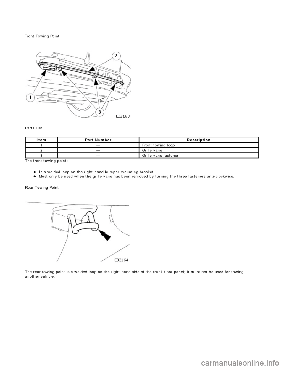
arts List
The front towing point:
Is a welded loop on the ri
ght-ha
nd bumper mounting bracket.
Mus
t only be used when the grille
vane has been removed by turning the three fasteners anti-clockwise.
Rear Towing Point
The rear towing point is a welded loop on the right-hand side of the trunk floor panel; it must not be used for towing
another vehicle.
It
em
Par
t Number
De
scription
1—Fr
ont towing loop
2—Gr
ille vane
3—Gr
ille vane fastener
F
ront Towing Point
Page 117 of 2490
Front Suspension - Fro
nt Stabilizer Bar
Re
moval and Installation
Materials
S
pecification
Cas
trol NTR
Remov
al
Na
me
R
ubber Suspension Insulator Lube
1. Raise front of vehicle and support on stands. Refer to Section
100-02.
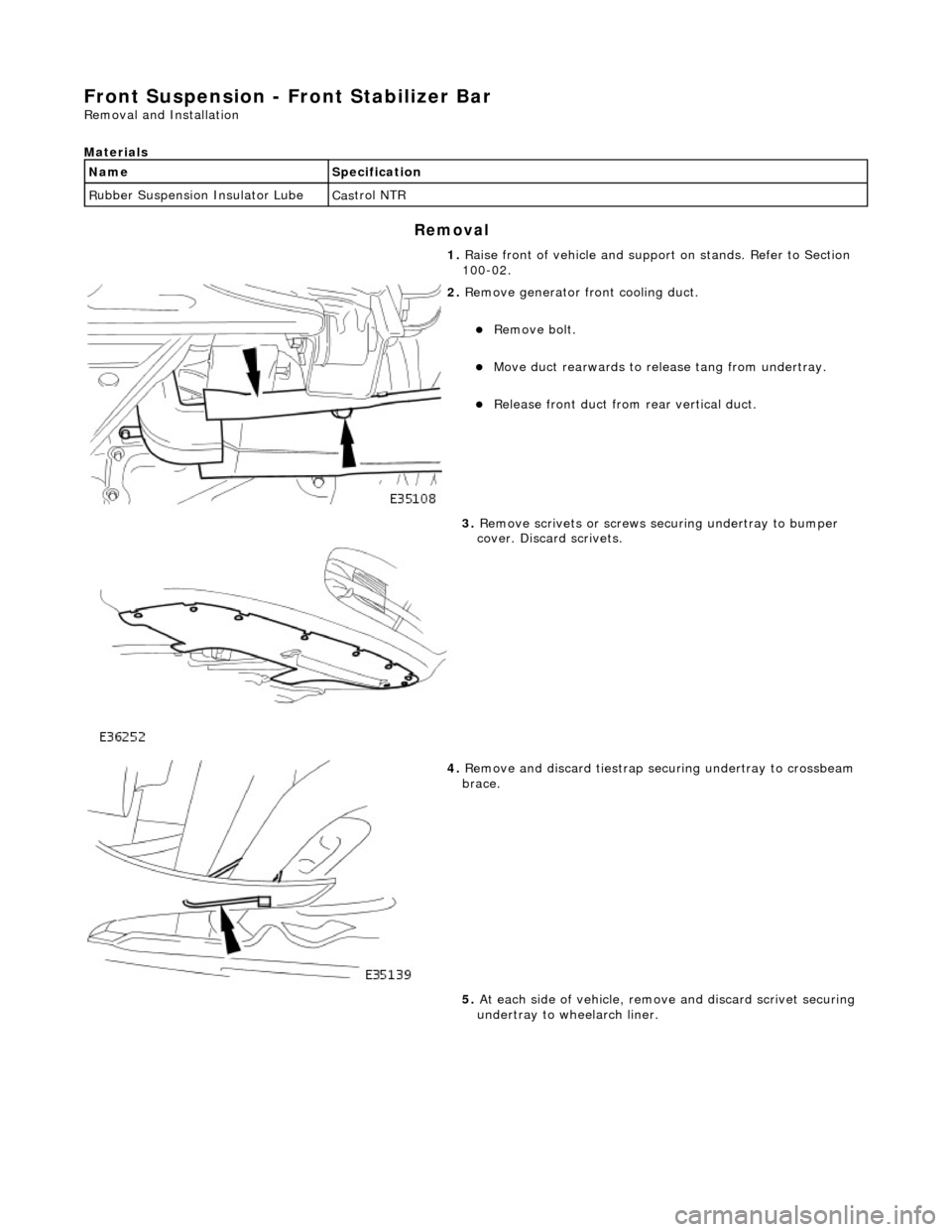
2. R
emove generator front cooling duct.
Re
move bolt.
Move duct rea
rwards to rele
ase tang from undertray.
R
elease front duct from rear vertical duct.
3. R
emove scrivets or screws se
curing undertray to bumper
cover. Discard scrivets.
4. R
emove and discard tiestrap securing undertray to crossbeam
brace.
5. At each side of vehicle, remo ve and discard scrivet securing
undertray to wheelarch liner.
Page 122 of 2490
Front Suspension - Front Stabilizer B
ar Bushing
Re
mo
val and Installation
Materials
S p
ecification
Cas
t
rol NTR
Remov
a
l
Na
m
e
R
u
bber Suspension Insulator Lube
1. Raise front of vehicle and support on stands. Refer to Section
100-02.
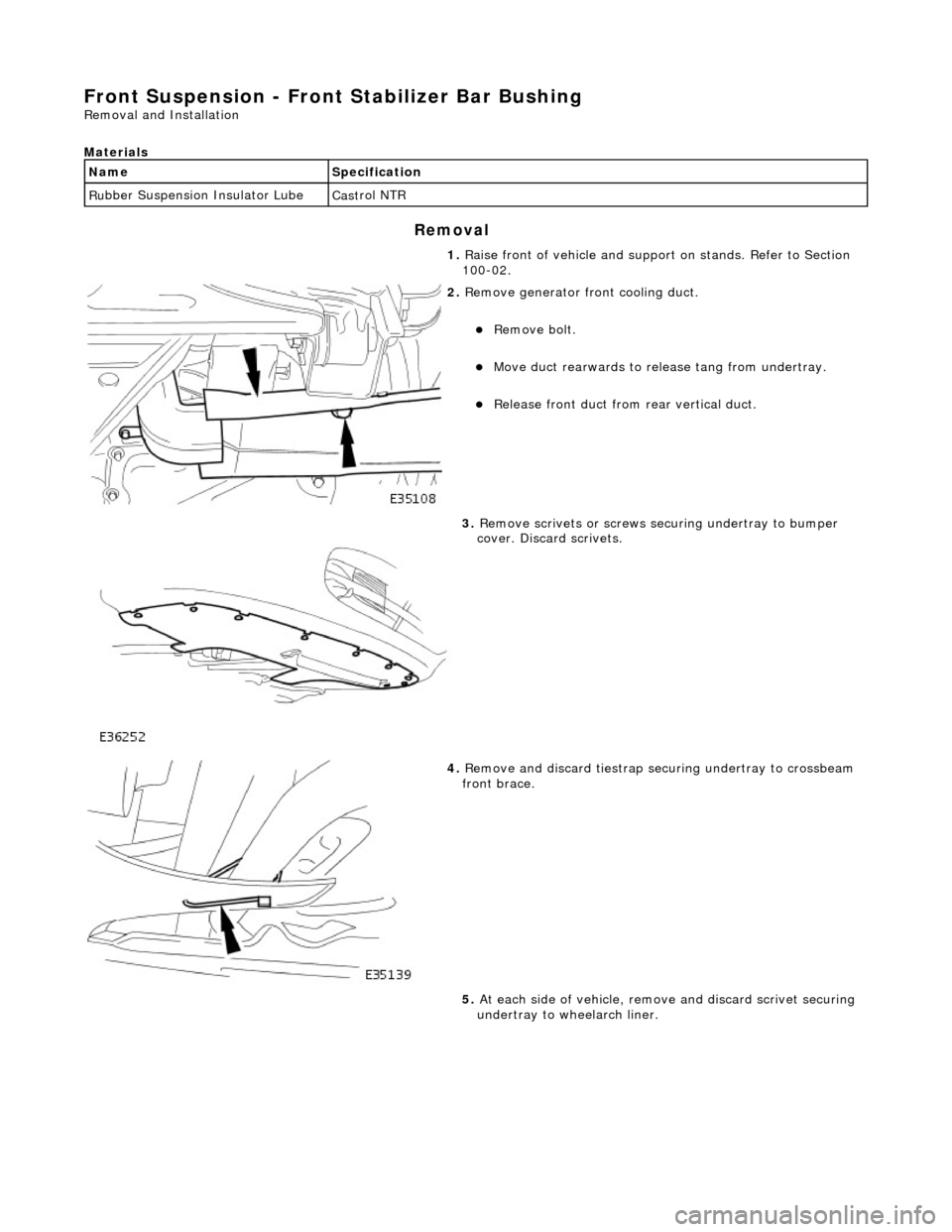
2. Re
move generator front cooling duct.
Re
mo
ve bolt.
Move duct rea
r
wards to rele
ase tang from undertray.
Re
lease front duct from rear vertical duct.
3. Re
move scrivets or screws se
curing undertray to bumper
cover. Discard scrivets.
4. Re
move and discard tiestrap securing undertray to crossbeam
front brace.
5. At each side of vehicle, remo ve and discard scrivet securing
undertray to wheelarch liner.
Page 125 of 2490
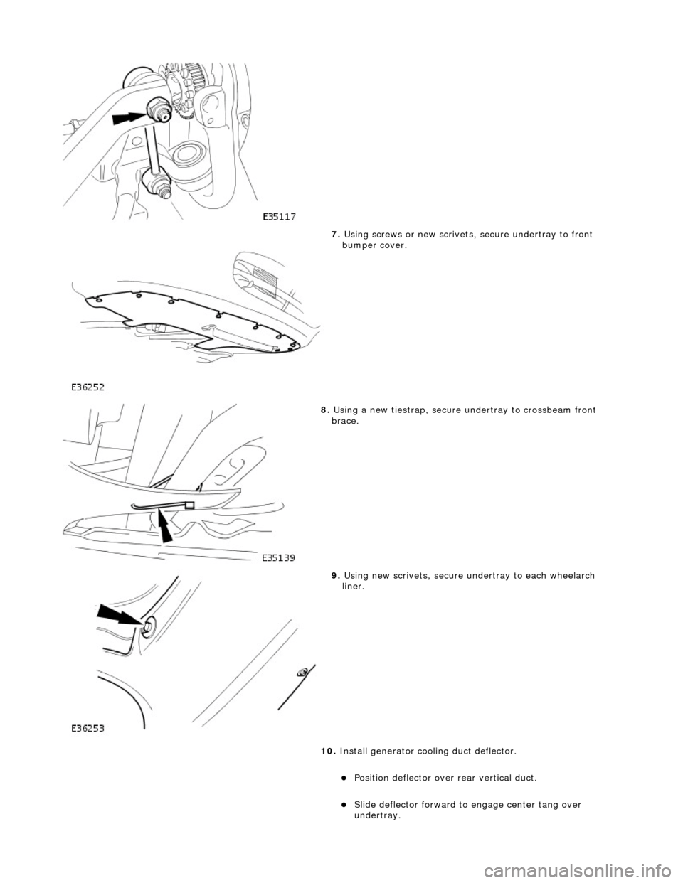
7. Using screws or new scrivets , secure undertray
to front
bumper cover.
8. Usi
ng a new tiestrap, secure undertray to crossbeam front
brace.
9. Usi
ng new scrivets, secure un
dertray to each wheelarch
liner.
10. Install generator cool ing duct deflector.
Po
sition deflector over
rear vertical duct.
Sl
ide deflector forward to
engage center tang over
undertray.
Page 1126 of 2490
Intake Air Distribution and Filtering - Charge Air Cooler Radiator
Remo
val and Installation
Remov
a
l
1.
Op
en the engine compartment and fit paintwork protection
sheets.
2. Disconnect the battery.
1. Remove the battery cover.
2. Disconnect the battery ground cable.
3. Remove the engine radiator and air conditioning condensor
assembly. Refer to operation 26.40.01.
4. Remove the grill assembly fo r access. Refer to operation
76.55.15.
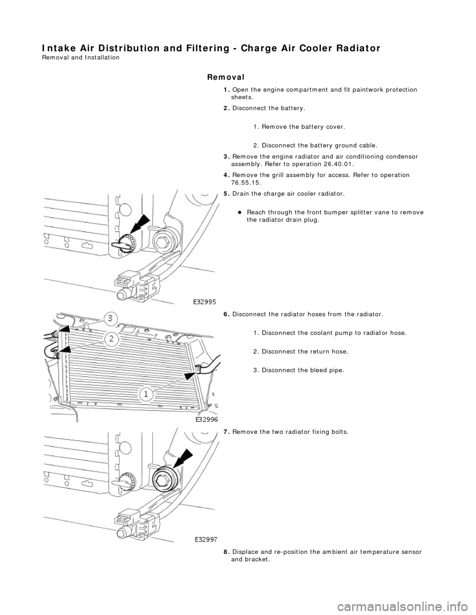
5. Drain th e charge air cooler radiator.
Reach t
hrough the front bumper
splitter vane to remove
the radiator drain plug.
6. Disc
onnect the radiator
hoses from the radiator.
1. Disconnect the coolant pump to radiator hose.
2. Disconnect the return hose.
3. Disconnect the bleed pipe.
7. Re
move the two radiator fixing bolts.
8. Displace and re-position the am bient air temperature sensor
and bracket.
Page 1920 of 2490
Direction indicator and side marker lamps
Each front direction indicator and side marker lamp is retained in the bumper cover by a lug at one end and a spring clip at
the other end. The side marker lamps are not electrically connected for certain markets.
The side repeater lamps are secured by sp ring clips on the lower edge of the lamp unit. In certain markets Jaguar leaper
badges are substituted for side repeater lamps.
Fog lamps
The fog lamps are located in recesses in the front bump er and secured by three screws. The la mps which are not
interchangeable left to right, are accessed from the rear of the bumper.
Operation
All lamps are controlled by the BPM which provides an appropriate output in response to an input received when a selected
switch is operated.
All lamps receive an input direct from th e BPM with the exception of the main be am, dip beam and front fog lamps which
receive an input from the BPM vi a the respective relays and fuses; refer to section 418-01.
Fault analysis must be undertaken using the PDU. Refer to Diagnosis and Testing.
Consult the relevant Electrical Guid e for details of circuit operation.
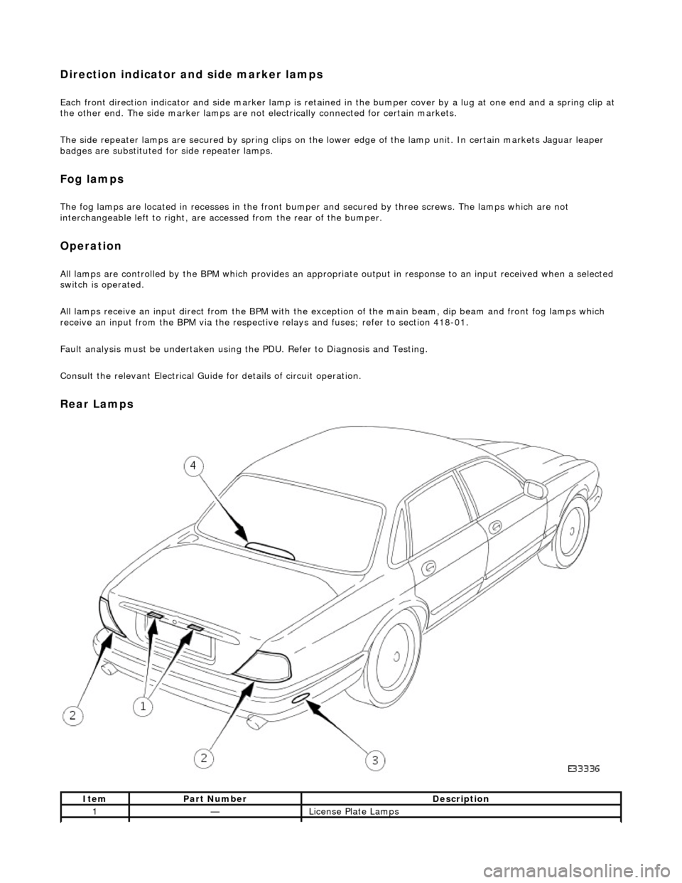
Rear Lamps
ItemPart NumberDescription
1—License Plate Lamps
Page 1926 of 2490
Exterior Lighting - Front Fog Lamp
Removal and Installation
Removal
Installation
1.
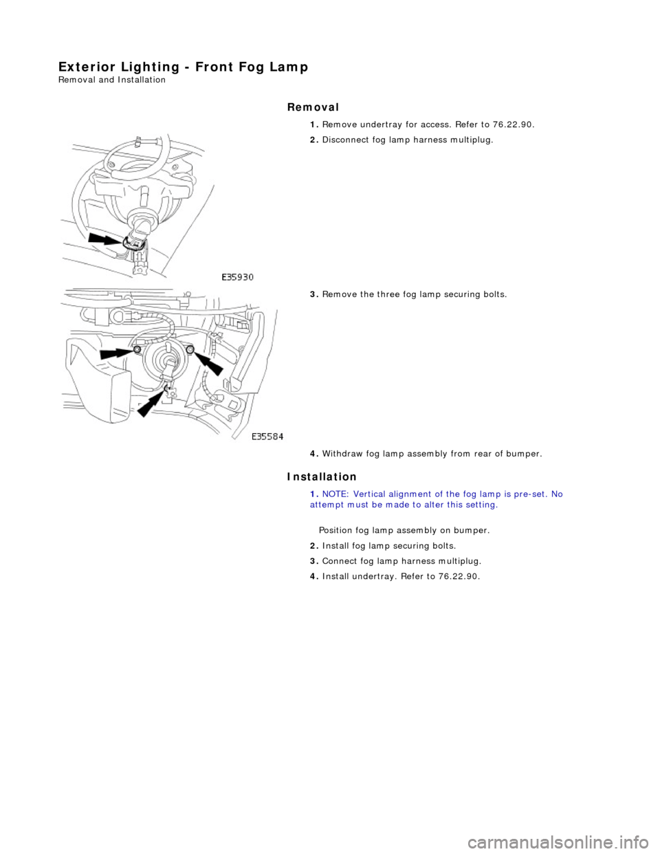
Remove undertray for ac cess. Refer to 76.22.90.
2. Disconnect fog lamp harness multiplug.
3. Remove the three fog la mp securing bolts.
4. Withdraw fog lamp assembly from rear of bumper.
1. NOTE: Vertical alignment of the fog lamp is pre-set. No
attempt must be made to alter this setting.
Position fog lamp assembly on bumper.
2. Install fog lamp securing bolts.
3. Connect fog lamp harness multiplug.
4. Install undertray. Refer to 76.22.90.
Page 1928 of 2490
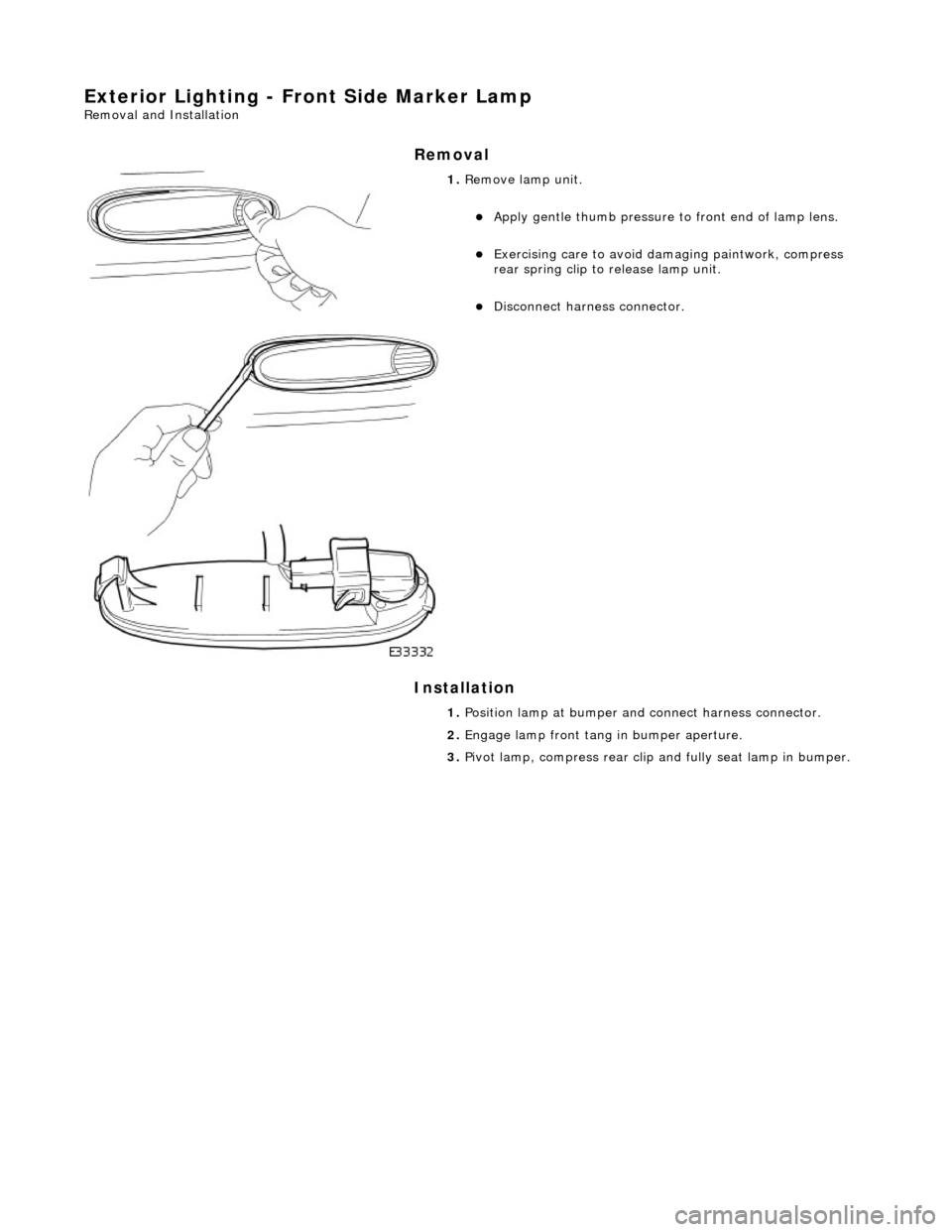
Exterior Lighting - Front Side Marker Lamp
Removal and Installation
Removal
Installation
1. Remove lamp unit.
Apply gentle thumb pressure to front end of lamp lens.
Exercising care to avoid damaging paintwork, compress
rear spring clip to release lamp unit.
Disconnect harness connector.
1. Position lamp at bumper an d connect harness connector.
2. Engage lamp front tang in bumper aperture.
3. Pivot lamp, compress rear clip and fully seat lamp in bumper.
Page 1929 of 2490

Exterior Lighting - Front Side Marker Lamp Bulb
Removal and Installation
Removal
1. Applying firm hand pressure to front end, pivot lamp assembly
for access to rear end.
2. Exercising care to avoid dama ging paintwork, use a small
screwdriver at rear end of lamp, to press and release retaining
tang.
3. Withdraw lamp from bumper for access and disconnect harness multiplug.
4. Rotate bulb holder 1/4 turn counter-clockwise to release it
from lamp assembly.
5. Withdraw bulb from holder.