Battery JAGUAR XFR 2010 1.G Workshop Manual
[x] Cancel search | Manufacturer: JAGUAR, Model Year: 2010, Model line: XFR, Model: JAGUAR XFR 2010 1.GPages: 3039, PDF Size: 58.49 MB
Page 810 of 3039
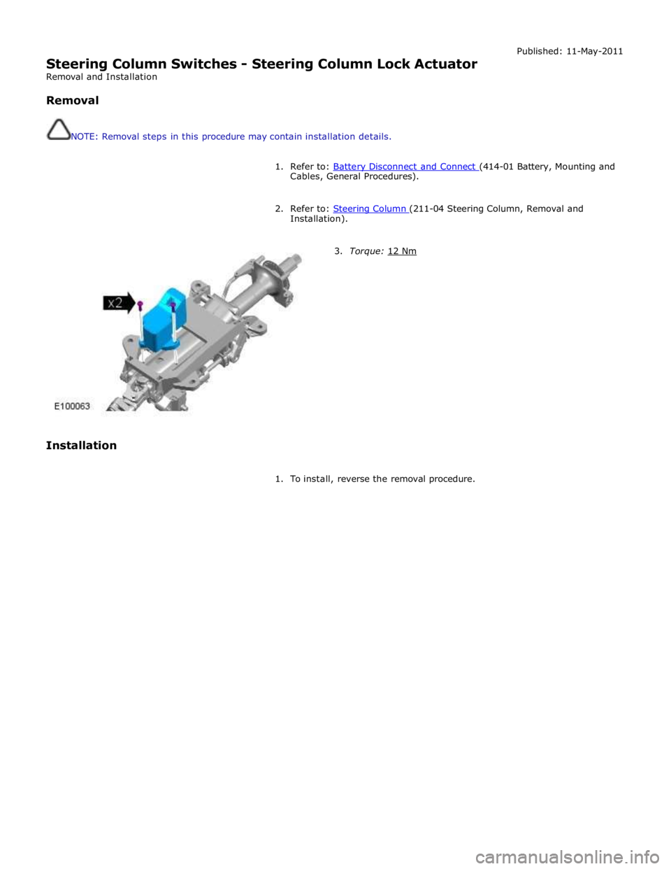
Steering Column Switches - Steering Column Lock Actuator
Removal and Installation
Removal
NOTE: Removal steps in this procedure may contain installation details. Published: 11-May-2011
1. Refer to: Battery Disconnect and Connect (414-01 Battery, Mounting and Cables, General Procedures).
2. Refer to: Steering Column (211-04 Steering Column, Removal and Installation).
Installation
3. Torque: 12 Nm
1. To install, reverse the removal procedure.
Page 816 of 3039
9. WEAK VALVE SPRINGS: When the needle oscillation becomes more violent as engine RPM is increased, weak valve
springs are indicated. The reading at idle could be relatively steady.
10. LATE VALVE TIMING: A steady but low reading could be caused by late valve timing.
11.
IGNITION TIMING RETARDED: Retarded ignition timing will produce a steady but somewhat low reading.
12.
INSUFFICIENT SPARK PLUG GAP: When spark plugs are gapped too close, a regular, small pulsation of the needle can
occur.
13. INTAKE LEAK: A low, steady reading can be caused by an intake manifold or throttle body gasket leak.
14.
BLOWN HEAD GASKET: A regular drop of fair magnitude can be caused by a blown head gasket or warped cylinder head
to cylinder block surface.
15.
RESTRICTED EXHAUST SYSTEM: When the engine is first started and is idled, the reading may be normal, but as the
engine RPM is increased, the back pressure caused by a clogged muffler, kinked tail pipe or other concerns will cause
the needle to slowly drop to 0 kPa (0 in-Hg). The needle then may slowly rise. Excessive exhaust clogging will cause
the needle to drop to a low point even if the engine is only idling.
When vacuum leaks are indicated, search out and correct the cause. Excess air leaking into the system will upset the fuel
mixture and cause concerns such as rough idle, missing on acceleration or burned valves. If the leak exists in an accessory
such as the power brake booster, the unit will not function correctly. Always repair vacuum leaks.
Engine Oil Pressure Check
NOTE: Prior to checking the engine oil pressure, a road test of 6 miles (10 kilometres), must be carried out. Do not
attempt to attain engine normal operating temperature by allowing the engine to idle.
1. Disconnect the battery ground cable. Refer to section 414-00 - Charging System - General Information of the workshop
manual
2. WARNINGS:
The spilling of hot engine oil is unavoidable during this procedure, care must be taken to prevent scalding.
Wear protective gloves.
Remove the engine oil filter element
REFER to: Oil Filter Element (303-01C Engine - V8 5.0L Petrol, Removal and Installation).
NOTE: Ensure the oil filter element is not contaminated during this procedure
3. Install the oil filter element into special tool (Oil filter adapter number 303-1451)
4. Install the special tool (Oil filter adapter number 303-1451) to the engine. Torque: 25 Nm
5. Install the special tool (Oil pressure testing gauge, 303-871) and tighten the union
6. Connect the battery ground cable
7. Refer to owner hand book, check and top-up the engine oil if required
8. Start and run the engine
9. Note the oil pressure readings with the engine running at idle and 3500 RPM
10.
Turn off the engine
11.
Disconnect the battery ground cable
12. Remove the special tools
1. Clean the components
13.
Install the engine oil filter element
REFER to: Oil Filter Element (303-01C Engine - V8 5.0L Petrol, Removal and Installation).
NOTE: Ensure the oil filter element is not contaminated during this procedure
14.
Connect the battery ground cable
15. Refer to owner hand book, check and top-up the engine oil if required
www.JagDocs.com
Page 827 of 3039
Published: 02-Jun-2011
Engine System - General Information - Leakage Test Using Smoke Test Equipment
General Procedures
CAUTION: The compressed air line supply pressure must be between 3.5 and 12 bar (50 and 175 psi) for the smoke test
equipment to function correctly. Do not exceed this pressure. Failure to follow this instruction may result in damage to the
smoke test equipment.
NOTES:
The vehicle battery must be in good condition and fully charged before carrying out this procedure.
On vehicles with 3.0L TDV6, it will be necessary to insert smoke at both air cleaner outlet pipes independently if the right
hand turbocharger and associated hoses are to be tested.
In some cases it may be necessary to remove undertrays, trim or engine covers to obtain access to all potential leak
locations.
Some variation in the illustrations may occur, but the essential information is always correct.
For further information regarding operation of the test equipment refer to the manufacturers operators manual supplied
with the kit.
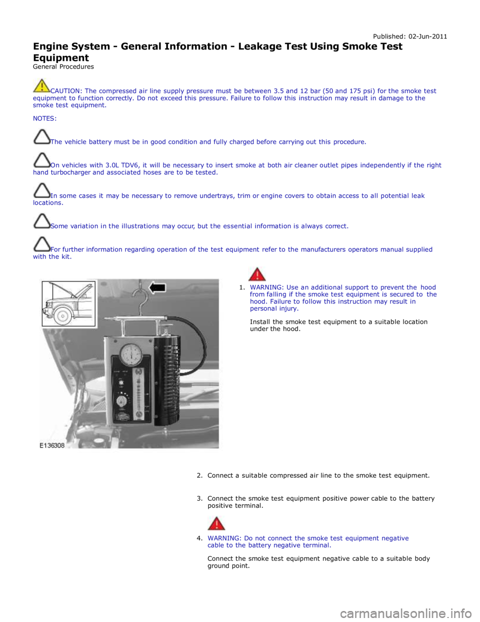
1. WARNING: Use an additional support to prevent the hood
from falling if the smoke test equipment is secured to the
hood. Failure to follow this instruction may result in
personal injury.
Install the smoke test equipment to a suitable location
under the hood.
2. Connect a suitable compressed air line to the smoke test equipment.
3. Connect the smoke test equipment positive power cable to the battery
positive terminal.
4. WARNING: Do not connect the smoke test equipment negative
cable to the battery negative terminal.
Connect the smoke test equipment negative cable to a suitable body
ground point.
Page 828 of 3039

5. NOTE: A flashing green light indicates low battery voltage.
In this case, place the battery on charge and make sure
that the battery is fully charged before using the smoke
test equipment.
Observe the power indicator lamp on the smoke test
equipment. Make sure that a continuous green light is
displayed.
6. NOTES:
In some cases it may be necessary to remove the air
cleaner(s) to allow access to the air cleaner outlet pipes.
In some cases it will be necessary to cap one of the
air cleaner outlet pipes. Use the blanking caps supplied in
the kit to cap the open orifice.
Disconnect the air cleaner outlet pipe(s).
Page 839 of 3039
Published: 09-Apr-2014
Engine System - General Information - Cylinder Compression Test V8 S/C 5.0L
Petrol
General Procedures
Check
CAUTION: Before disconnecting or removing components, make sure the area around the joint faces and connections are
clean. Plug open connections to prevent contamination.
NOTES:
Removal steps in this procedure may contain installation details.
Some variation in the illustrations may occur, but the essential information is always correct.
The vehicle battery must be in good condition and fully charged before carrying out this procedure.
1. Refer to: Ignition Coil-On-Plug - V8 S/C 5.0L Petrol (303-07B Engine Ignition - V8 5.0L Petrol/V8 S/C 5.0L Petrol, Removal and Installation).
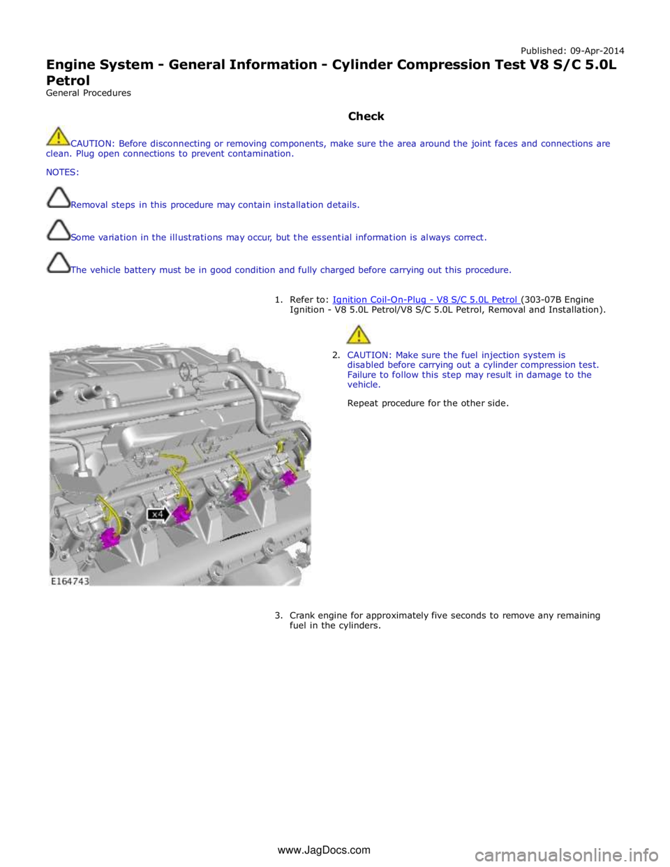
2. CAUTION: Make sure the fuel injection system is
disabled before carrying out a cylinder compression test.
Failure to follow this step may result in damage to the
vehicle.
Repeat procedure for the other side.
3. Crank engine for approximately five seconds to remove any remaining
fuel in the cylinders. www.JagDocs.com
Page 840 of 3039

4. NOTE: Dry cylinder compression test.
Install the compression test gauge.
5. NOTES:
This step requires the aid of another technician.
Print graphic number E164747 in step 11. Use this
graphic to record each cylinder compression figure.
The vehicle battery must be in good condition and fully
charged before carrying out this procedure.
Crank the engine for 10 seconds and record the figure
displayed on the compression test gauge. Make sure the
pressure is released from the compression test gauge after
each cylinder recording. Repeat the process for all cylinders.
Page 842 of 3039
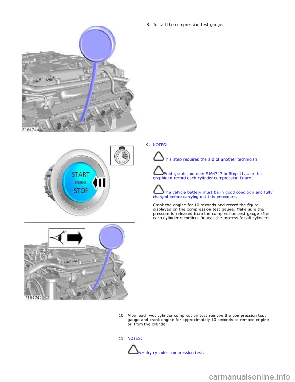
8. Install the compression test gauge.
9. NOTES:
This step requires the aid of another technician.
Print graphic number E164747 in Step 11. Use this
graphic to record each cylinder compression figure.
The vehicle battery must be in good condition and fully
charged before carrying out this procedure.
Crank the engine for 10 seconds and record the figure
displayed on the compression test gauge. Make sure the
pressure is released from the compression test gauge after
each cylinder recording. Repeat the process for all cylinders.
10.
After each wet cylinder compression test remove the compression test
gauge and crank engine for approximately 10 seconds to remove engine
oil from the cylinder
11. NOTES:
A= dry cylinder compression test.
Page 868 of 3039
cooling jets and the timing chain lubrication jets.
The oil returns to the oil pan under gravity. Large drain holes through the cylinder heads and cylinder block ensure the rapid
return of the oil to the sump pan. System replenishment is through the oil filler cap on the LH cylinder head cover.
An oil evacuation tube is installed to allow oil to be drawn from the sump pan. The upper end of the oil evacuation tube is
located under the oil filler cap.
An oil drain plug is installed in the RH side of the sump pan.
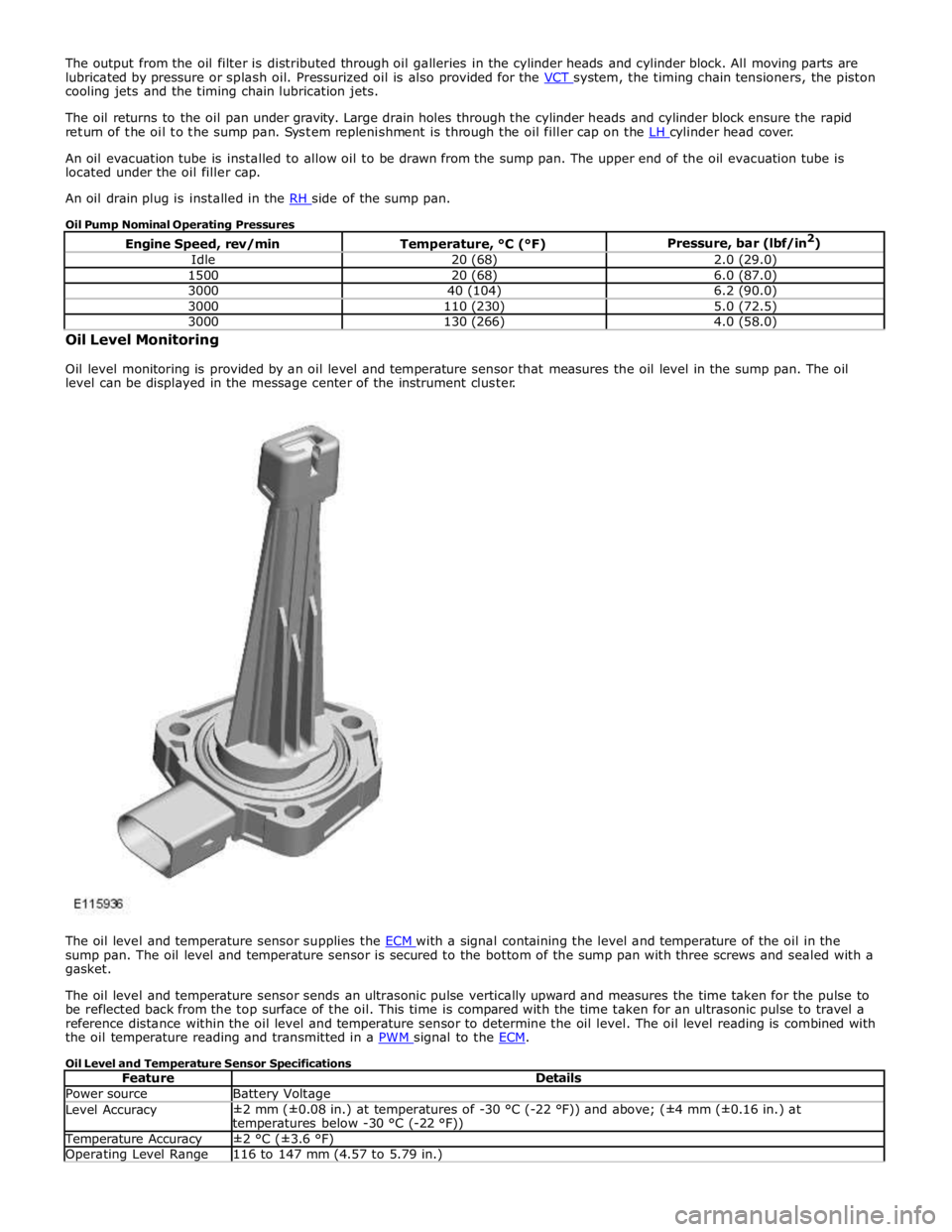
Oil Pump Nominal Operating Pressures
Engine Speed, rev/min Temperature, °C (°F) Pressure, bar (lbf/in2
) Idle 20 (68) 2.0 (29.0) 1500 20 (68) 6.0 (87.0) 3000 40 (104) 6.2 (90.0) 3000 110 (230) 5.0 (72.5) 3000 130 (266) 4.0 (58.0) Oil Level Monitoring
Oil level monitoring is provided by an oil level and temperature sensor that measures the oil level in the sump pan. The oil
level can be displayed in the message center of the instrument cluster.
The oil level and temperature sensor supplies the ECM with a signal containing the level and temperature of the oil in the sump pan. The oil level and temperature sensor is secured to the bottom of the sump pan with three screws and sealed with a
gasket.
The oil level and temperature sensor sends an ultrasonic pulse vertically upward and measures the time taken for the pulse to
be reflected back from the top surface of the oil. This time is compared with the time taken for an ultrasonic pulse to travel a
reference distance within the oil level and temperature sensor to determine the oil level. The oil level reading is combined with
the oil temperature reading and transmitted in a PWM signal to the ECM.
Oil Level and Temperature Sensor Specifications
Feature Details Power source Battery Voltage Level Accuracy ±2 mm (±0.08 in.) at temperatures of -30 °C (-22 °F)) and above; (±4 mm (±0.16 in.) at
temperatures below -30 °C (-22 °F)) Temperature Accuracy ±2 °C (±3.6 °F) Operating Level Range 116 to 147 mm (4.57 to 5.79 in.)
Page 885 of 3039
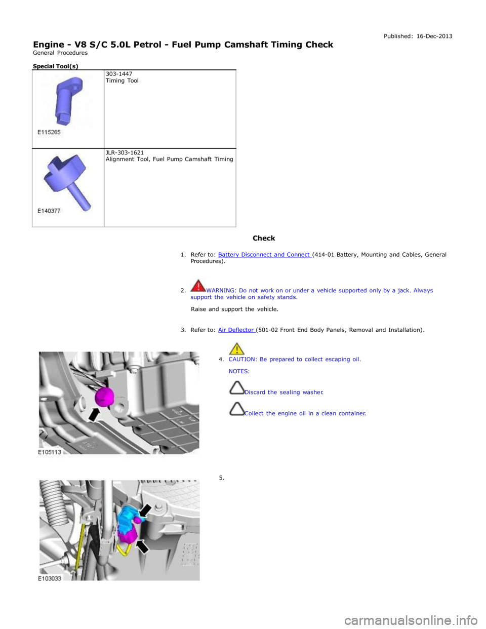
Engine - V8 S/C 5.0L Petrol - Fuel Pump Camshaft Timing Check
General Procedures
Special Tool(s)
303-1447
Timing Tool
JLR-303-1621
Alignment Tool, Fuel Pump Camshaft Timing
Check Published: 16-Dec-2013
1. Refer to: Battery Disconnect and Connect (414-01 Battery, Mounting and Cables, General Procedures).
2. WARNING: Do not work on or under a vehicle supported only by a jack. Always
support the vehicle on safety stands.
Raise and support the vehicle.
3. Refer to: Air Deflector (501-02 Front End Body Panels, Removal and Installation).
4. CAUTION: Be prepared to collect escaping oil.
NOTES:
Discard the sealing washer.
Collect the engine oil in a clean container.
5.
Page 889 of 3039
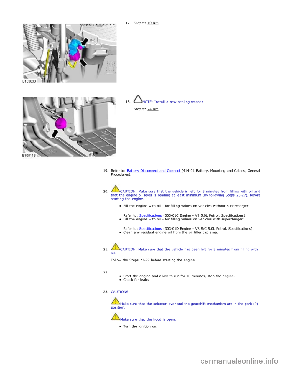
17.
18. Torque: 10 Nm
NOTE: Install a new sealing washer.
Torque: 24 Nm
19.
20. Refer to: Battery Disconnect and Connect (414-01 Battery, Mounting and Cables, General Procedures).
CAUTION: Make sure that the vehicle is left for 5 minutes from filling with oil and
that the engine oil level is reading at least minimum (by following Steps 23-27), before
starting the engine.
Fill the engine with oil - for filling values on vehicles without supercharger:
Refer to: Specifications (303-01C Engine - V8 5.0L Petrol, Specifications). Fill the engine with oil - for filling values on vehicles with supercharger:
Refer to: Specifications (303-01D Engine - V8 S/C 5.0L Petrol, Specifications). Clean any residual engine oil from the oil filler cap area.
21.
oil. CAUTION: Make sure that the vehicle has been left for 5 minutes from filling with
Follow the Steps 23-27 before starting the engine.
22.
Start the engine and allow to run for 10 minutes, stop the engine.
Check for leaks.
23. CAUTIONS:
Make sure that the selector lever and the gearshift mechanism are in the park (P)
position.
Make sure that the hood is open.
Turn the ignition on.