catalytic converter JAGUAR XFR 2010 1.G User Guide
[x] Cancel search | Manufacturer: JAGUAR, Model Year: 2010, Model line: XFR, Model: JAGUAR XFR 2010 1.GPages: 3039, PDF Size: 58.49 MB
Page 1364 of 3039
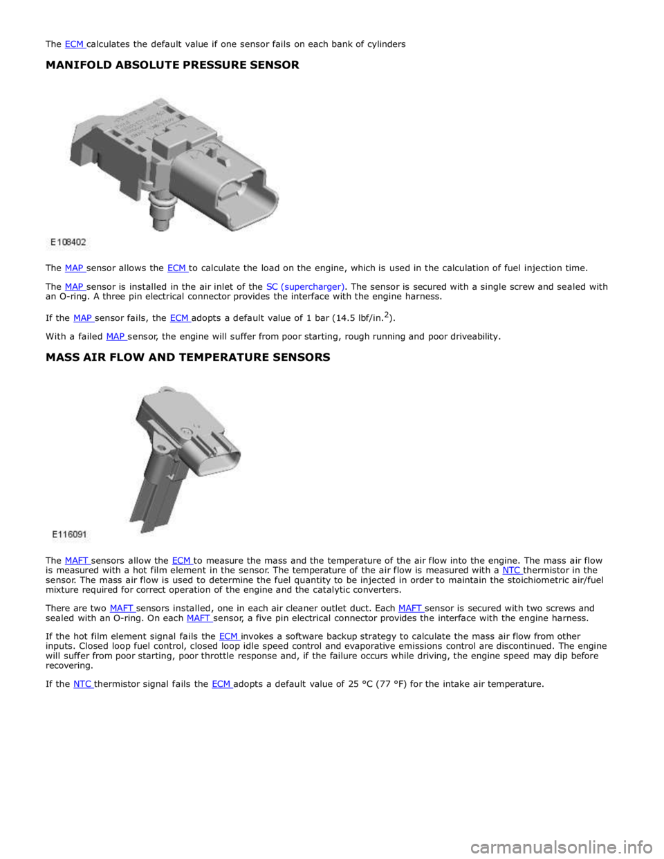
MANIFOLD ABSOLUTE PRESSURE SENSOR
The MAP sensor allows the ECM to calculate the load on the engine, which is used in the calculation of fuel injection time.
The MAP sensor is installed in the air inlet of the SC (supercharger). The sensor is secured with a single screw and sealed with an O-ring. A three pin electrical connector provides the interface with the engine harness.
If the MAP sensor fails, the ECM adopts a default value of 1 bar (14.5 lbf/in.2
). With a failed MAP sensor, the engine will suffer from poor starting, rough running and poor driveability.
MASS AIR FLOW AND TEMPERATURE SENSORS
The MAFT sensors allow the ECM to measure the mass and the temperature of the air flow into the engine. The mass air flow is measured with a hot film element in the sensor. The temperature of the air flow is measured with a NTC thermistor in the sensor. The mass air flow is used to determine the fuel quantity to be injected in order to maintain the stoichiometric air/fuel
mixture required for correct operation of the engine and the catalytic converters.
There are two MAFT sensors installed, one in each air cleaner outlet duct. Each MAFT sensor is secured with two screws and sealed with an O-ring. On each MAFT sensor, a five pin electrical connector provides the interface with the engine harness.
If the hot film element signal fails the ECM invokes a software backup strategy to calculate the mass air flow from other inputs. Closed loop fuel control, closed loop idle speed control and evaporative emissions control are discontinued. The engine
will suffer from poor starting, poor throttle response and, if the failure occurs while driving, the engine speed may dip before
recovering.
If the NTC thermistor signal fails the ECM adopts a default value of 25 °C (77 °F) for the intake air temperature.
Page 1365 of 3039
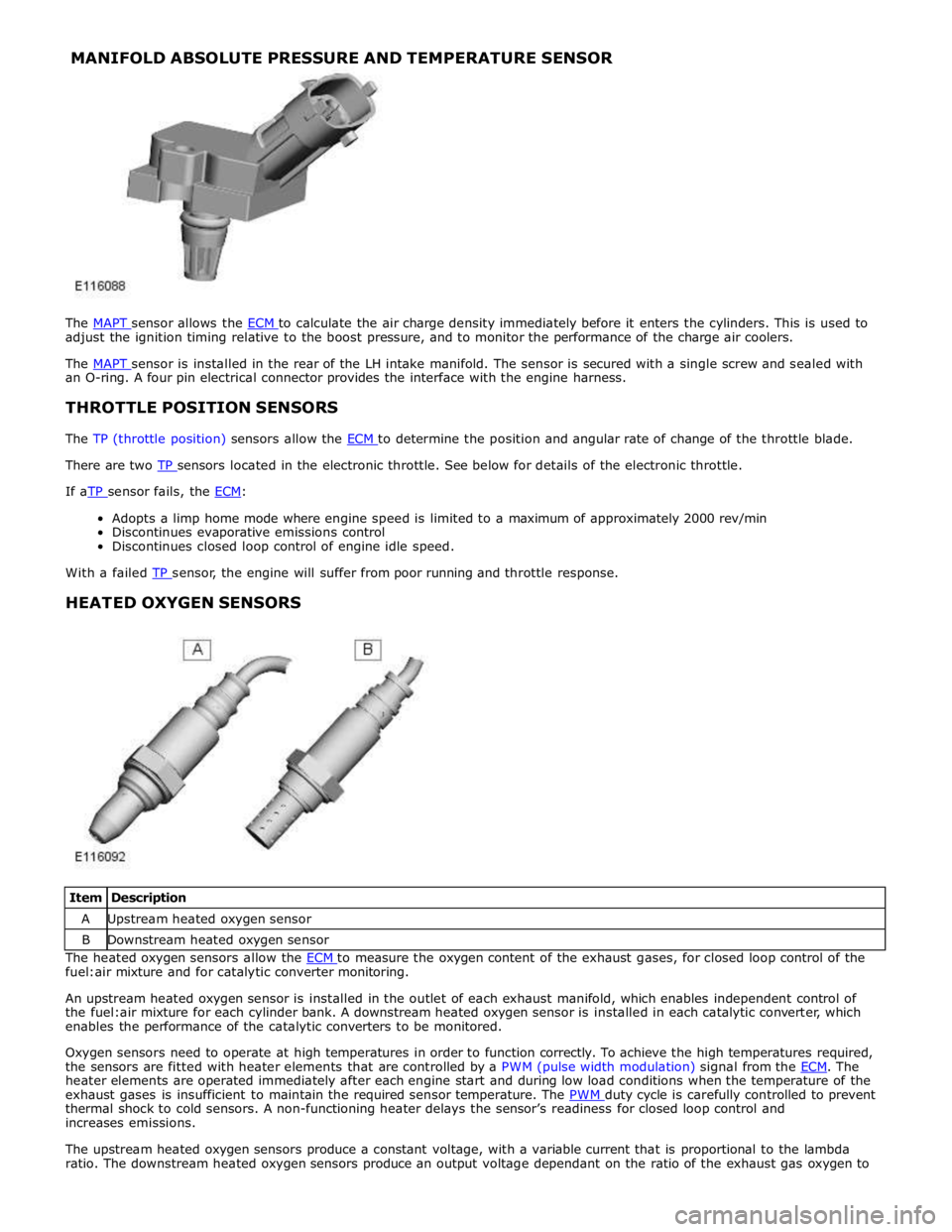
MANIFOLD ABSOLUTE PRESSURE AND TEMPERATURE SENSOR
The MAPT sensor allows the ECM to calculate the air charge density immediately before it enters the cylinders. This is used to adjust the ignition timing relative to the boost pressure, and to monitor the performance of the charge air coolers.
The MAPT sensor is installed in the rear of the LH intake manifold. The sensor is secured with a single screw and sealed with an O-ring. A four pin electrical connector provides the interface with the engine harness.
THROTTLE POSITION SENSORS
The TP (throttle position) sensors allow the ECM to determine the position and angular rate of change of the throttle blade. There are two TP sensors located in the electronic throttle. See below for details of the electronic throttle. If aTP sensor fails, the ECM:
Adopts a limp home mode where engine speed is limited to a maximum of approximately 2000 rev/min
Discontinues evaporative emissions control
Discontinues closed loop control of engine idle speed.
With a failed TP sensor, the engine will suffer from poor running and throttle response.
HEATED OXYGEN SENSORS
Item Description A Upstream heated oxygen sensor B Downstream heated oxygen sensor The heated oxygen sensors allow the ECM to measure the oxygen content of the exhaust gases, for closed loop control of the fuel:air mixture and for catalytic converter monitoring.
An upstream heated oxygen sensor is installed in the outlet of each exhaust manifold, which enables independent control of
the fuel:air mixture for each cylinder bank. A downstream heated oxygen sensor is installed in each catalytic converter, which
enables the performance of the catalytic converters to be monitored.
Oxygen sensors need to operate at high temperatures in order to function correctly. To achieve the high temperatures required,
the sensors are fitted with heater elements that are controlled by a PWM (pulse width modulation) signal from the ECM. The heater elements are operated immediately after each engine start and during low load conditions when the temperature of the
exhaust gases is insufficient to maintain the required sensor temperature. The PWM duty cycle is carefully controlled to prevent thermal shock to cold sensors. A non-functioning heater delays the sensor’s readiness for closed loop control and
increases emissions.
The upstream heated oxygen sensors produce a constant voltage, with a variable current that is proportional to the lambda
ratio. The downstream heated oxygen sensors produce an output voltage dependant on the ratio of the exhaust gas oxygen to
Page 1387 of 3039

Published: 19-Aug-2013
Electronic Engine Controls - V8 S/C 5.0L Petrol - Engine Coolant Temperature
(ECT) Sensor
Removal and Installation
Removal
NOTES:
Some variation in the illustrations may occur, but the essential information is always correct.
Removal steps in this procedure may contain installation details.
1. WARNING: Do not work on or under a vehicle supported only by a jack.
Always support the vehicle on safety stands.
Raise and support the vehicle.
2. Refer to: Cooling System Partial Draining, Filling and Bleeding (303-03B Engine Cooling - V6 3.0L Petrol, General Procedures).
3. Refer to: Catalytic Converter RH (309-00C Exhaust System - V8 5.0L Petrol/V8 S/C 5.0L Petrol, Removal and Installation).
4. Torque: 48 Nm
Page 1394 of 3039
Published: 11-May-2011
Electronic Engine Controls - V8 S/C 5.0L Petrol - Heated Oxygen Sensor
(HO2S) LH
Removal and Installation
Removal
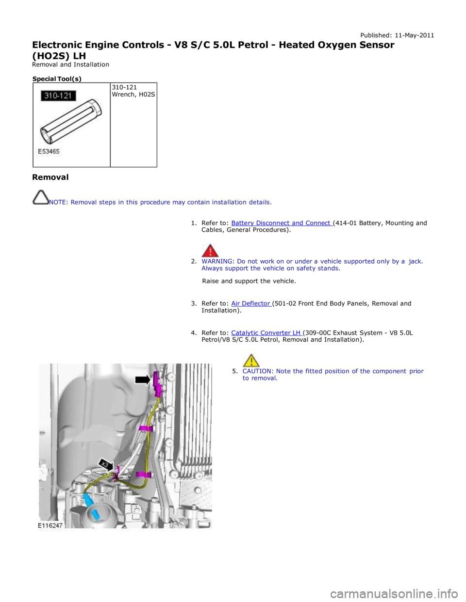
NOTE: Removal steps in this procedure may contain installation details.
1. Refer to: Battery Disconnect and Connect (414-01 Battery, Mounting and Cables, General Procedures).
2. WARNING: Do not work on or under a vehicle supported only by a jack.
Always support the vehicle on safety stands.
Raise and support the vehicle.
3. Refer to: Air Deflector (501-02 Front End Body Panels, Removal and Installation).
4. Refer to: Catalytic Converter LH (309-00C Exhaust System - V8 5.0L Petrol/V8 S/C 5.0L Petrol, Removal and Installation).
5. CAUTION: Note the fitted position of the component prior
to removal. 310-121
Wrench, H02S Special Tool(s)
Page 1396 of 3039
Published: 11-May-2011
Electronic Engine Controls - V8 S/C 5.0L Petrol - Heated Oxygen Sensor
(HO2S) RH
Removal and Installation
Removal
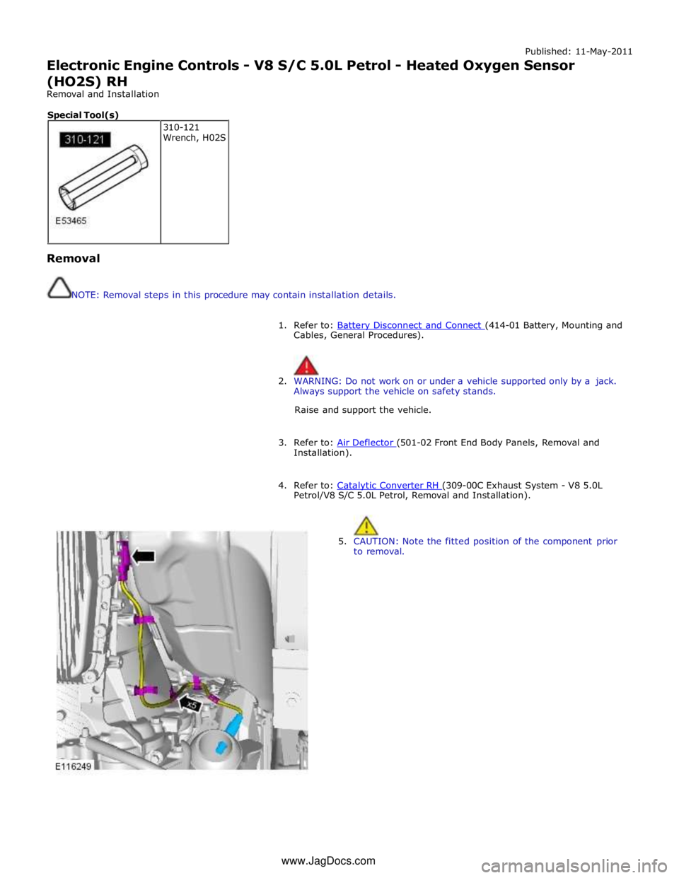
NOTE: Removal steps in this procedure may contain installation details.
1. Refer to: Battery Disconnect and Connect (414-01 Battery, Mounting and Cables, General Procedures).
2. WARNING: Do not work on or under a vehicle supported only by a jack.
Always support the vehicle on safety stands.
Raise and support the vehicle.
3. Refer to: Air Deflector (501-02 Front End Body Panels, Removal and Installation).
4. Refer to: Catalytic Converter RH (309-00C Exhaust System - V8 5.0L Petrol/V8 S/C 5.0L Petrol, Removal and Installation).
5. CAUTION: Note the fitted position of the component prior
to removal. 310-121
Wrench, H02S Special Tool(s) www.JagDocs.com
Page 1471 of 3039

Published: 12-Sep-2011
Automatic Transmission/Transaxle - TDV6 3.0L Diesel /V8 5.0L Petrol/V8 S/C 5.0L Petrol - Transmission, Transmission Fluid Cooler and Transmission Fluid
Cooler Tubes V8 5.0L Petrol/V8 S/C 5.0L Petrol
Removal and Installation
Removal
CAUTION: Make sure that all openings are sealed. Use new blanking caps.
NOTE: Some variation in the illustrations may occur, but the essential information is always correct.
1. Refer to: Battery Disconnect and Connect (414-01 Battery, Mounting and Cables, General Procedures).
2. WARNING: Make sure to support the vehicle with axle stands.
Raise and support the vehicle.
3. Refer to: Catalytic Converter RH (309-00C Exhaust System - V8 5.0L Petrol/V8 S/C 5.0L Petrol, Removal and Installation).
4. Refer to: Catalytic Converter LH (309-00C Exhaust System - V8 5.0L Petrol/V8 S/C 5.0L Petrol, Removal and Installation).
5.
Page 1486 of 3039

22.
23.
24.
Refer to: Catalytic Converter LH (309-00C Exhaust System - V8 5.0L Petrol/V8 S/C 5.0L Petrol, Removal and Installation).
25. Refer to: Catalytic Converter RH (309-00C Exhaust System - V8 5.0L Petrol/V8 S/C 5.0L Petrol, Removal and Installation).
26. Refer to: Battery Disconnect and Connect (414-01 Battery, Mounting and Cables, General Procedures).
27. Check and top up the cooling system as required.
28. Set the heater controls to HOT.
29. CAUTION: Observe the engine temperature warning light. If the
warning light is displayed, switch off immediately and allow to cool.
Failure to follow this instruction may cause damage to the vehicle.
Start the engine and allow to idle until hot air is emited at the face
registers.
Page 1488 of 3039

Published: 12-Sep-2011
Automatic Transmission/Transaxle - TDV6 3.0L Diesel /V8 5.0L Petrol/V8 S/C 5.0L Petrol - Transmission and Transmission Fluid Cooler V8 5.0L Petrol/V8 S/C 5.0L Petrol
Removal and Installation
Removal
CAUTION: Make sure that all openings are sealed. Use new blanking caps.
NOTE: Some variation in the illustrations may occur, but the essential information is always correct.
1. Refer to: Battery Disconnect and Connect (414-01 Battery, Mounting and Cables, General Procedures).
2. WARNING: Make sure to support the vehicle with axle stands.
Raise and support the vehicle.
3. Refer to: Catalytic Converter RH (309-00C Exhaust System - V8 5.0L Petrol/V8 S/C 5.0L Petrol, Removal and Installation).
4. Refer to: Catalytic Converter LH (309-00C Exhaust System - V8 5.0L Petrol/V8 S/C 5.0L Petrol, Removal and Installation).
5.
Page 1502 of 3039

20.
21.
22.
Refer to: Catalytic Converter LH (309-00C Exhaust System - V8 5.0L Petrol/V8 S/C 5.0L Petrol, Removal and Installation).
23. Refer to: Catalytic Converter RH (309-00C Exhaust System - V8 5.0L Petrol/V8 S/C 5.0L Petrol, Removal and Installation).
24. Refer to: Battery Disconnect and Connect (414-01 Battery, Mounting and Cables, General Procedures).
25. Check and top up the cooling system as required.
26. Set the heater controls to HOT.
27. CAUTION: Observe the engine temperature warning light. If the
warning light is displayed, switch off immediately and allow to cool.
Failure to follow this instruction may cause damage to the vehicle.
Start the engine and allow to idle until hot air is emited at the face
registers. www.JagDocs.com
Page 1504 of 3039

Published: 11-May-2011
Automatic Transmission/Transaxle - TDV6 3.0L Diesel /V8 5.0L Petrol/V8 S/C 5.0L Petrol - Transmission V8 5.0L Petrol/V8 S/C 5.0L Petrol
Removal
1. Refer to: Battery Disconnect and Connect (414-01 Battery, Mounting and Cables, General Procedures).
2. WARNING: Make sure to support the vehicle with axle stands.
Raise and support the vehicle.
3. Refer to: Catalytic Converter RH (309-00C Exhaust System - V8 5.0L Petrol/V8 S/C 5.0L Petrol, Removal and Installation).
4. Refer to: Catalytic Converter LH (309-00C Exhaust System - V8 5.0L Petrol/V8 S/C 5.0L Petrol, Removal and Installation).
5.
6.