navigation system JAGUAR XFR 2010 1.G Workshop Manual
[x] Cancel search | Manufacturer: JAGUAR, Model Year: 2010, Model line: XFR, Model: JAGUAR XFR 2010 1.GPages: 3039, PDF Size: 58.49 MB
Page 21 of 3039

Quiescent Drain
Battery Report Form – In Service Batteries OnlyDiagnosis and TestingCharging System414-01: Battery, Mounting and CablesSpecificationDescription and OperationComponent Location
Overview
System Operation and Component DescriptionDiagnosis and TestingBatteryGeneral ProceduresBattery Disconnect and ConnectRemoval and InstallationBattery414-02C: Generator and Regulator - V8 5.0L Petrol/V8 S/C 5.0L PetrolSpecificationDescription and OperationComponent Location
Overview
System Operation and Component DescriptionRemoval and InstallationGenerator - V8 S/C 5.0L Petrol415: Information and Entertainment Systems
415-00: Information and Entertainment System - General Information
Description and OperationNavigation System Map UpdatesDiagnosis and TestingInformation and Entertainment System
Cellular Phone
Navigation System415-01A: Information and Entertainment SystemSpecification
Description and OperationAudio SystemComponent Location
Overview
System Operation and Component DescriptionSpeakersComponent Location
Overview
Page 22 of 3039

Operation and
Component DescriptionCellular PhoneComponent
Location
Overview
System Operation
and Component DescriptionNavigation SystemComponent Location
Overview
System Operation and Component DescriptionVideo SystemComponent
Location
Overview
System Operation
and Component DescriptionDiagnosis and TestingInformation and Entertainment SystemRemoval and InstallationAudio Unit
Audio Unit Antenna Amplifier
Audio and Climate Control Assembly
Front Door Speaker
Information and Entertainment Display
Information and Entertainment Module
Instrument Panel Speaker
Rear Door Speaker
Steering Wheel Audio Controls
Subwoofer Amplifier
Subwoofer Speaker
Satellite Radio Tuner415-01B: Information and Entertainment System - DTC: Audio Input Control Module
Diagnosis and TestingAudio Input Control Module417: Lighting
417-01: Exterior LightingSpecificationDescription and OperationComponent Location
Overview
System Operation and Component DescriptionDiagnosis and TestingHeadlampsGeneral ProceduresHeadlamp Adjustment (86.40.18)
Page 24 of 3039

System Operation and Component DescriptionDiagnosis and TestingAnti-Theft - ActiveRemoval and InstallationAnti-Theft Alarm Horn (86.52.03)419-01B: Anti-Theft - Passive
Description and OperationComponent Location
Overview
System Operation and Component DescriptionDiagnosis and TestingAnti-Theft - Passive419-05: Telematics
Diagnosis and TestingTelematics419-07: Navigation System
Description and Operation Diagnosis and TestingNavigation SystemRemoval and InstallationNavigation System Antenna (86.62.06)
Navigation System Module (86.62.05)419-08: Cellular Phone
Removal and InstallationBluetooth Module419-10: Multifunction Electronic ModulesSpecificationDescription and OperationComponent Location
Overview
System Operation and Component DescriptionDiagnosis and TestingDriver Door Module (DDM)
Remote Keyless Entry (RKE) Module
Passenger Door Module (PDM)Removal and InstallationDriver Door Module (DDM)
Driver Seat Module (DSM)
Passenger Door Module (PDM)
Rear Door Module (RDM)5: Body and Paint
501: Body and Paint
501-02: Front End Body Panels
Page 251 of 3039
Published: 12-May-2014
General Information - Diagnostic Trouble Code (DTC) Index DTC: Touch
Screen Display (FCDIM)
Description and Operation
Touch Screen (TS)
CAUTION: Diagnosis by substitution from a donor vehicle is NOT acceptable. Substitution of control modules does not
guarantee confirmation of a fault, and may also cause additional faults in the vehicle being tested and/or the donor vehicle.
NOTES:
If a control module or a component is suspect and the vehicle remains under manufacturer warranty, refer to the Warranty
Policy and Procedures manual, or determine if any prior approval programme is in operation, prior to the installation of a new
module/component.
Generic scan tools may not read the codes listed, or may read only 5-digit codes. Match the 5 digits from the scan tool to
the first 5 digits of the 7-digit code listed to identify the fault (the last 2 digits give extra information read by the
manufacturer-approved diagnostic system).
When performing voltage or resistance tests, always use a digital multimeter accurate to three decimal places, and with
an up-to-date calibration certificate. When testing resistance always take the resistance of the digital multimeter leads into
account.
Check and rectify basic faults before beginning diagnostic routines involving pinpoint tests.
Inspect connectors for signs of water ingress, and pins for damage and/or corrosion.
If DTCs are recorded and, after performing the pinpoint tests, a fault is not present, an intermittent concern may be the
cause. Always check for loose connections and corroded terminals.
Check DDW for open campaigns. Refer to the corresponding bulletins and SSMs which may be valid for the specific
customer complaint and carry out the recommendations as required.
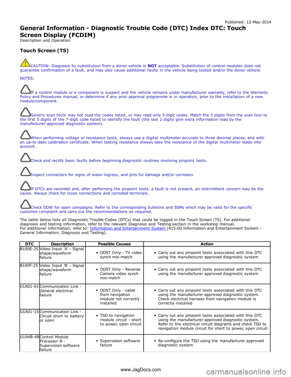
The table below lists all Diagnostic Trouble Codes (DTCs) that could be logged in the Touch Screen (TS). For additional
diagnosis and testing information, refer to the relevant Diagnosis and Testing section in the workshop manual.
For additional information, refer to: Information and Entertainment System (415-00 Information and Entertainment System - General Information, Diagnosis and Testing).
DTC Description Possible Causes Action B100E-25
Video Input 'A' - Signal
shape/waveform
failure
ODST Only - TV video
synch mis-match
Carry out any pinpoint tests associated with this DTC
using the manufacturer approved diagnostic system B100F-25
Video Input 'B' - Signal
shape/waveform
failure
ODST Only - Reverse
Camera video synch
mis-match
Carry out any pinpoint tests associated with this DTC
using the manufacturer approved diagnostic system U1A01-01
Communication Link -
General electrical
failure
ODST Only - cable
from navigation
module not correctly
installed
Carry out any pinpoint tests associated with this DTC
using the manufacturer approved diagnostic system.
Check electrical harness from navigation module is
correctly installed U1A01-15
Communication Link -
Circuit short to battery
or open
TSD to navigation
module circuit - short
to power, open circuit
Carry out any pinpoint tests associated with this DTC
using the manufacturer approved diagnostic system.
Refer to the electrical circuit diagrams and check TSD to
navigation module circuit for short to power, open circuit U1A4B-48
Control Module
Processor B -
Supervision software
failure
Supervision software
failure
Re-configure the TSD using the manufacturer approved
diagnostic system www.JagDocs.com
Page 276 of 3039

DTC Description Possible Causes Action circuit
Short circuit to ground
medium speed CAN positive
circuit
Short circuit between
medium speed CAN positive
circuit and medium speed
CAN negative circuit U0156-4A
Lost communication
with information
center "A" -
Incorrect component
installed
The information and
entertainment module has
detected a mismatch
between the hardware
connected and the expected
hardware
Module has incorrect serial
number
Suspect incorrect instrument cluster installed. Refer
to the warranty policy and procedures manual if
module is suspect. Check the system is operating
correctly and there are no DTCs U0159-00
Lost communication
with parking assist
control module "A" -
No sub type
information
General failure
Parking aid module, battery
supply circuit, open circuit
Parking aid module, ground
supply circuit, open circuit
Parking aid module medium
speed CAN negative circuit,
open circuit
parking aid module medium
speed CAN positive circuit,
open circuit
Carry out any pinpoint tests associated with this
DTC using the manufacturer approved diagnostic
system. Check parking aid module for DTCs and
refer to the relevant DTC Index. Refer to electrical
circuit diagrams, check battery and ground supplies,
to parking aid module for open circuit. Check
medium speed CAN negative and positive harness
to parking aid module, repair as necessary U0163-00
Lost communication
with navigation
control module - No
sub type
information
General failure
Navigation system module,
battery supply circuit, open
circuit
Navigation system module
ground supply circuit, open
circuit
Navigation system module,
MOST network, open circuit
Navigation system module
not configured
Navigation system module
failure
Check the navigation system module for DTCs and
refer to the relevant DTC index. Using the
manufacturing approved diagnostic system carry out
MOST ring test. Using the manufacturers approved
diagnostic system re-configure the navigation
system module. Refer to electrical circuit diagrams
check battery and ground supplies to navigation
system module for open circuit. Repair as necessary.
Refer to the warranty policy and procedures manual
if module is suspect. Check the system is operating
correctly and there are no DTCs U0163-4A
Lost communication
with navigation
control module -
Incorrect component
installed
The information and
entertainment module has
detected a mismatch
between the hardware
connected and the expected
hardware
Module has incorrect serial
number
Suspect incorrect navigation module installed. Refer
to the warranty policy and procedures manual if
module is suspect. Check the system is operating
correctly and there are no DTCs U0184-00
Lost communication
with radio - No sub
type information
General failure
Integrated audio module
battery supply circuit, open
circuit
Integrated audio module
ground supply circuit, open
circuit
Integrated audio module
MOST network, open circuit
Integrated audio module not
configured
Integrated audio module
failure
Check the integrated audio module for DTCs and
refer to the relevant DTC index. Using the
manufacturing approved diagnostic system carry out
MOST ring test. Using the manufacturers approved
diagnostic system re-configure the integrated audio
module. Refer to electrical circuit diagrams check
battery and ground supplies to integrated audio
module for open circuit. Repair as necessary. Refer
to the warranty policy and procedures manual if
module is suspect. Check the system is operating
correctly and there are no DTCs U0184-4A
Lost communication
with radio -
Incorrect component
installed
The information and
entertainment module has
detected a mismatch
between the hardware
connected and the expected
hardware
Suspect incorrect integrated audio module installed.
Refer to the warranty policy and procedures manual
if module is suspect. Check the system is operating
correctly and there are no DTCs
Page 1687 of 3039
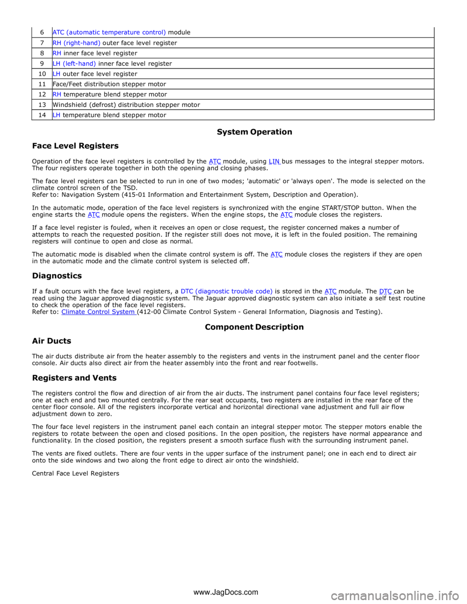
7 RH (right-hand) outer face level register 8 RH inner face level register 9 LH (left-hand) inner face level register 10 LH outer face level register 11 Face/Feet distribution stepper motor 12 RH temperature blend stepper motor 13 Windshield (defrost) distribution stepper motor 14 LH temperature blend stepper motor
Face Level Registers System Operation
Operation of the face level registers is controlled by the ATC module, using LIN bus messages to the integral stepper motors. The four registers operate together in both the opening and closing phases.
The face level registers can be selected to run in one of two modes; 'automatic' or 'always open'. The mode is selected on the
climate control screen of the TSD.
Refer to: Navigation System (415-01 Information and Entertainment System, Description and Operation).
In the automatic mode, operation of the face level registers is synchronized with the engine START/STOP button. When the
engine starts the ATC module opens the registers. When the engine stops, the ATC module closes the registers.
If a face level register is fouled, when it receives an open or close request, the register concerned makes a number of
attempts to reach the requested position. If the register still does not move, it is left in the fouled position. The remaining
registers will continue to open and close as normal.
The automatic mode is disabled when the climate control system is off. The ATC module closes the registers if they are open in the automatic mode and the climate control system is selected off.
Diagnostics
If a fault occurs with the face level registers, a DTC (diagnostic trouble code) is stored in the ATC module. The DTC can be read using the Jaguar approved diagnostic system. The Jaguar approved diagnostic system can also initiate a self test routine
to check the operation of the face level registers.
Refer to: Climate Control System (412-00 Climate Control System - General Information, Diagnosis and Testing).
Air Ducts Component Description
The air ducts distribute air from the heater assembly to the registers and vents in the instrument panel and the center floor
console. Air ducts also direct air from the heater assembly into the front and rear footwells.
Registers and Vents
The registers control the flow and direction of air from the air ducts. The instrument panel contains four face level registers;
one at each end and two mounted centrally. For the rear seat occupants, two registers are installed in the rear face of the
center floor console. All of the registers incorporate vertical and horizontal directional vane adjustment and full air flow
adjustment down to zero.
The four face level registers in the instrument panel each contain an integral stepper motor. The stepper motors enable the
registers to rotate between the open and closed positions. In the open position, the registers have normal appearance and
functionality. In the closed position, the registers present a smooth surface flush with the surrounding instrument panel.
The vents are fixed outlets. There are four vents in the upper surface of the instrument panel; one in each end to direct air
onto the side windows and two along the front edge to direct air onto the windshield.
Central Face Level Registers
www.JagDocs.com
Page 1820 of 3039

Published: 11-May-2011
Information and Message Center - Information and Message Center - Overview
Description and Operation
OVERVIEW
The message center is a LCD (liquid crystal display) located in a central position in the instrument cluster. The message center
receives CAN (controller area network) bus, LIN (local interconnect network) bus, and hardwired signals from other vehicle
system control modules to display current vehicle status information. Depending on message importance, the message center
will be backlit in white, amber or red.
The message center will display:
Fuel level
Trip computer information
Gear selected
Speed control information
Vehicle map
Clock
Turn by turn satellite navigation
Voice control text
JaguarDrive Control system messages.
Operation of the message center is controlled by software within the instrument cluster.
Refer to: Instrument Cluster (413-01 Instrument Cluster, Description and Operation).
Page 1826 of 3039
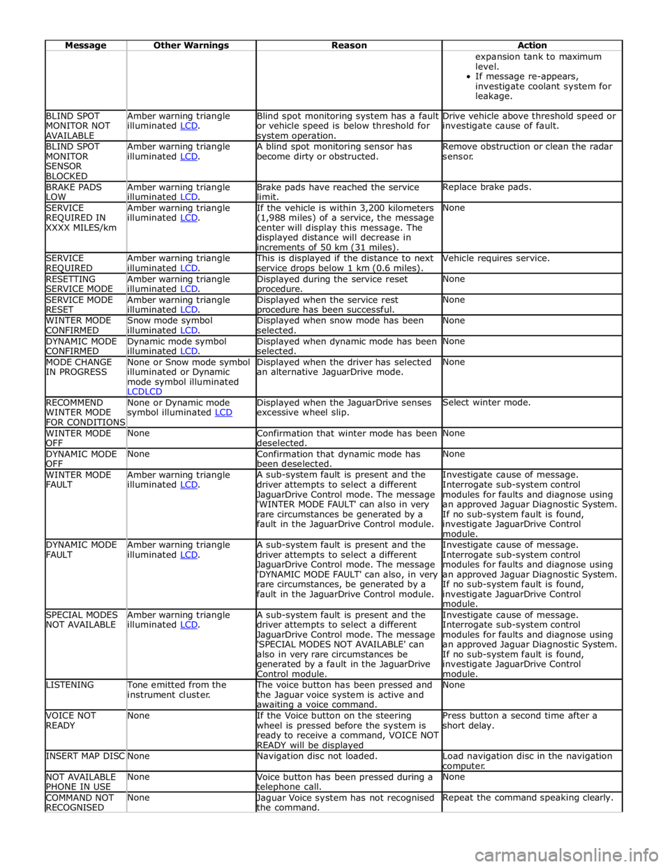
Message Other Warnings Reason Action expansion tank to maximum
level.
If message re-appears,
investigate coolant system for
leakage. BLIND SPOT
MONITOR NOT
AVAILABLE Amber warning triangle
illuminated LCD. Blind spot monitoring system has a fault
or vehicle speed is below threshold for system operation. Drive vehicle above threshold speed or
investigate cause of fault. BLIND SPOT
MONITOR
SENSOR
BLOCKED Amber warning triangle
illuminated LCD. A blind spot monitoring sensor has
become dirty or obstructed. Remove obstruction or clean the radar
sensor. BRAKE PADS
LOW Amber warning triangle
illuminated LCD. Brake pads have reached the service
limit. Replace brake pads. SERVICE
REQUIRED IN
XXXX MILES/km Amber warning triangle
illuminated LCD. If the vehicle is within 3,200 kilometers
(1,988 miles) of a service, the message
center will display this message. The
displayed distance will decrease in
increments of 50 km (31 miles). None SERVICE
REQUIRED Amber warning triangle
illuminated LCD. This is displayed if the distance to next
service drops below 1 km (0.6 miles). Vehicle requires service. RESETTING
SERVICE MODE Amber warning triangle
illuminated LCD. Displayed during the service reset procedure. None SERVICE MODE
RESET Amber warning triangle
illuminated LCD. Displayed when the service rest procedure has been successful. None WINTER MODE
CONFIRMED Snow mode symbol
illuminated LCD. Displayed when snow mode has been
selected. None DYNAMIC MODE
CONFIRMED Dynamic mode symbol
illuminated LCD. Displayed when dynamic mode has been
selected. None MODE CHANGE
IN PROGRESS None or Snow mode symbol
illuminated or Dynamic
mode symbol illuminated
LCDLCD Displayed when the driver has selected
an alternative JaguarDrive mode. None RECOMMEND
WINTER MODE
FOR CONDITIONS None or Dynamic mode
symbol illuminated LCD Displayed when the JaguarDrive senses
excessive wheel slip. Select winter mode. WINTER MODE
OFF None
Confirmation that winter mode has been
deselected. None DYNAMIC MODE
OFF None
Confirmation that dynamic mode has
been deselected. None WINTER MODE
FAULT Amber warning triangle
illuminated LCD. A sub-system fault is present and the
driver attempts to select a different
JaguarDrive Control mode. The message
'WINTER MODE FAULT' can also in very
rare circumstances be generated by a
fault in the JaguarDrive Control module. Investigate cause of message.
Interrogate sub-system control
modules for faults and diagnose using
an approved Jaguar Diagnostic System.
If no sub-system fault is found,
investigate JaguarDrive Control
module. DYNAMIC MODE
FAULT Amber warning triangle
illuminated LCD. A sub-system fault is present and the
driver attempts to select a different
JaguarDrive Control mode. The message
'DYNAMIC MODE FAULT' can also, in very
rare circumstances, be generated by a
fault in the JaguarDrive Control module. Investigate cause of message.
Interrogate sub-system control
modules for faults and diagnose using
an approved Jaguar Diagnostic System.
If no sub-system fault is found,
investigate JaguarDrive Control
module. SPECIAL MODES
NOT AVAILABLE Amber warning triangle
illuminated LCD. A sub-system fault is present and the
driver attempts to select a different
JaguarDrive Control mode. The message
'SPECIAL MODES NOT AVAILABLE' can
also in very rare circumstances be
generated by a fault in the JaguarDrive
Control module. Investigate cause of message.
Interrogate sub-system control
modules for faults and diagnose using
an approved Jaguar Diagnostic System.
If no sub-system fault is found,
investigate JaguarDrive Control
module. LISTENING Tone emitted from the
instrument cluster. The voice button has been pressed and
the Jaguar voice system is active and awaiting a voice command. None VOICE NOT
READY None
If the Voice button on the steering
wheel is pressed before the system is
ready to receive a command, VOICE NOT
READY will be displayed Press button a second time after a
short delay. INSERT MAP DISC None Navigation disc not loaded.
Load navigation disc in the navigation
computer. NOT AVAILABLE
PHONE IN USE None
Voice button has been pressed during a telephone call. None COMMAND NOT
RECOGNISED None
Jaguar Voice system has not recognised
the command. Repeat the command speaking clearly.
Page 1915 of 3039
Published: 24-Mar-2014
Information and Entertainment System - General Information - Navigation
System Map Updates
Description and Operation
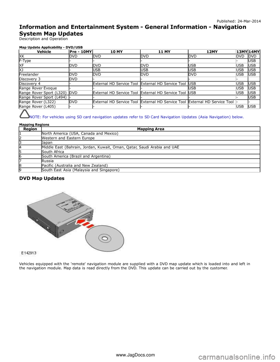
Map Update Applicability - DVD/USB
Vehicle Pre - 10MY 10 MY 11 MY 12MY 13MY 14MY XK DVD DVD DVD DVD DVD DVD F-Type - - - - - USB XF DVD DVD DVD USB USB USB XJ - USB USB USB USB USB Freelander DVD DVD DVD DVD USB USB Discovery 3 DVD - - - - Discovery 4 - External HD Service Tool External HD Service Tool USB USB USB Range Rover Evoque - - - USB USB USB Range Rover Sport (L320) DVD External HD Service Tool External HD Service Tool USB USB USB Range Rover Sport (L494) - - - - - USB Range Rover (L322) DVD External HD Service Tool External HD Service Tool External HD Service Tool - - Range Rover (L405) - - - - USB USB
NOTE: For vehicles using SD card navigation updates refer to SD Card Navigation Updates (Asia Navigation) below.
Mapping Regions
Region Mapping Area 1 North America (USA, Canada and Mexico) 2 Western and Eastern Europe 3 Japan 4 Middle East (Bahrain, Jordan, Kuwait, Oman, Qatar, Saudi Arabia and UAE 5 South Africa 6 South America (Brazil and Argentina) 7 Russia 8 Pacific (Australia and New Zealand) 9 South East Asia (Malaysia and Singapore)
DVD Map Updates
Vehicles equipped with the 'remote' navigation module are supplied with a DVD map update which is loaded into and left in
the navigation module. Map data is read directly from the DVD. This update can be carried out by the customer. www.JagDocs.com
Page 1930 of 3039
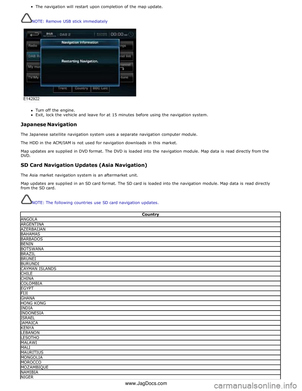
The navigation will restart upon completion of the map update.
NOTE: Remove USB stick immediately
Turn off the engine.
Exit, lock the vehicle and leave for at 15 minutes before using the navigation system.
Japanese Navigation
The Japanese satellite navigation system uses a separate navigation computer module.
The HDD in the ACM/IAM is not used for navigation downloads in this market.
Map updates are supplied in DVD format. The DVD is loaded into the navigation module. Map data is read directly from the
DVD.
SD Card Navigation Updates (Asia Navigation)
The Asia market navigation system is an aftermarket unit.
Map updates are supplied in an SD card format. The SD card is loaded into the navigation module. Map data is read directly
from the SD card.
NOTE: The following countries use SD card navigation updates.
Country ANGOLA ARGENTINA AZERBAIJAN BAHAMAS BARBADOS BENIN BOTSWANA BRAZIL BRUNEI BURUNDI CAYMAN ISLANDS CHILE CHINA COLOMBIA EGYPT FIJI GHANA HONG KONG INDIA INDONESIA ISRAEL JAMAICA KENYA LEBANON LESOTHO MALAWI MALI MAURITIUS MONGOLIA MOROCCO MOZAMBIQUE NAMIBIA NIGER www.JagDocs.com