warning light JAGUAR XFR 2010 1.G User Guide
[x] Cancel search | Manufacturer: JAGUAR, Model Year: 2010, Model line: XFR, Model: JAGUAR XFR 2010 1.GPages: 3039, PDF Size: 58.49 MB
Page 496 of 3039
JaguarDrive Control Sub-System Faults
If a fault occurs in a sub-system, the driver is alerted by the illumination of a warning indicator and/or an appropriate message
for that sub-system in the instrument cluster message center. No JaguarDrive Control message will be shown when a failed
sub-system displays its own message.
When a sub-system fault is present and the driver attempts to select a different JaguarDrive Control mode or at the next
ignition on cycle, a message 'WINTER MODE FAULT' or 'DYNAMIC MODE FAULT' will appear in the message center. This
generally implies that the JaguarDrive Control system has a fault, but only because a sub-system fault is preventing its
operation. This message will be displayed once per ignition cycle, but is repeated if a further selection is made by the driver
using the JaguarDrive Control buttons or at the next ignition on cycle.
NOTE: The message 'WINTER MODE FAULT' or 'DYNAMIC MODE FAULT' can also in very rare circumstances be generated
by a fault in the JaguarDrive Control module.
It is not possible for the JaguarDrive Control module to cause any fault behavior (warning indicator illumination or message
generation) in any of the sub-systems. Illumination of a sub-system warning indicator and/or a sub-system related message
will never be associated with a JaguarDrive Control module or JaguarDrive Control system fault.
The sub-system control modules can detect a fault with the CAN (controller area network) bus signal from the transmission
selector module. If a fault in the JaguarDrive Control system is detected, the sub-system control modules will operate in the
'special modes off' setting. The sub-system control modules will record a fault code for a failure of the JaguarDrive Control CAN signal. These faults can be retrieved using the Jaguar approved diagnostic tool and will provide useful information to indicate
investigation of the JaguarDrive Selector module or the CAN bus network. JaguarDrive Control System or Control Module Fault
If a fault occurs in the JaguarDrive Control system, all button icon LED (light emitting diode)'s will be turned off (background
illumination will remain on) and pressing of the JaguarDrive Control buttons is ignored. The instrument cluster message center
will display a message 'WINTER MODE FAULT' or 'DYNAMIC MODE FAULT' when the fault occurs, if the fault is present and the
driver attempts to select a special mode (if the control module is able to do this) or at the next ignition on cycle.
The JaguarDrive Control buttons and control module (JaguarDrive Selector module) are an integral unit. If a fault occurs in
either component, the whole unit will require replacement, however, this is extremely unlikely.
CAN Bus Faults
If a CAN bus fault exists and prevents JaguarDrive Control system operation, all of the JaguarDrive Control button icon LED's will be illuminated and rotation pressing of the JaguarDrive Control buttons is ignored.
If the instrument cluster does not receive a JaguarDrive Control system CAN bus message from the JaguarDrive Control module, the message 'SPECIAL MODE UNAVAILABLE' will be displayed when the fault occurs and will be repeated at every
ignition on cycle.
User Error
A special mode change while DSC or ABS is active (this includes ABS cycling) may be misinterpreted as a system fault.
Page 583 of 3039
If the concern becomes evident during this check, verify it fits the description given before the road test. If the concern is not
evident, attempt to duplicate the condition using the information from the description.
If a concern exists, use the Symptom Chart in order to isolate it to a specific sub-system and condition description. From this
description, a list of possible sources can be used to further narrow the cause to a specific component or condition.
Symptom Chart
Symptom Possible Cause Action Brakes noisy
Brake pads
Brake discs GO to Pinpoint Test A. Vibration when brakes are
applied
Wheels/tires out of balance
Wheel hub nuts loose
Brake caliper mounting bolts loose
Brake pads
Foreign material/scratches/corrosion
on brake disc contact surfaces
Excessive brake disc thickness
variation
Excessive brake disc runout
Wheel bearing wear or failure
Suspension bushing wear or failure
Steering bushing wear or failure GO to Pinpoint Test B. The brakes pull or drift
Tire pressures/wear
Brake calipers
Brake pads
Brake discs
Wheel alignment adjustment
Wheel bearing
Suspension bushings and ball joints GO to Pinpoint Test C. The pedal feels spongy
Air in brake hydraulic system
Leak in hydraulic system
Brake booster/master cylinder
Brake pads GO to Pinpoint Test D. The pedal goes down fast
Air in brake hydraulic system
Leak in hydraulic system
Brake booster/master cylinder
Brake pads GO to Pinpoint Test E. The pedal goes down
slowly
Air in brake hydraulic system
Brake booster/master cylinder GO to Pinpoint Test F. Excessive brake pedal
effort required
Brake pads
Brake booster GO to Pinpoint Test G. Brake lockup during light
brake pedal force
Brake pads
Brake calipers GO to Pinpoint Test H. Brakes drag
Parking brake control
applied/malfunction
Seized parking brake cables
Seized brake caliper slide pins
Seized brake caliper
Brake booster
Pedal gear GO to Pinpoint Test I. Excessive/Erratic brake
pedal travel
Hydraulic system
Brake pads Brake
discs
Hub and bearing assembly GO to Pinpoint Test J. The red brake warning
indicator is always on
Fluid level
Brake master cylinder fluid level
sensor
Parking brake control Fill the system to specification. Check for leaks.
Install a new brake master cylinder fluid reservoir as
required.
REFER to: Brake Fluid Reservoir (206-06 Hydraulic Brake Actuation, Removal and Installation).
Page 590 of 3039

Does the brake pedal return to its original position? Yes
No action required, vehicle is OK.
No
GO to K2. K2: CHECK FOR BRAKE PEDAL BINDING 1 Disconnect the brake booster from the brake pedal. Check the brake pedal to ensure free operation. Is the brake pedal operating freely? Yes
Install a new brake booster as required. REFER to:
Brake Booster (206-07 Power Brake Actuation, Removal and Installation), Brake Booster - RHD (206-07, Removal and Installation).
Re-test the system for normal operation.
No
Repair or install new brake pedal. Re-test the system for normal operation. Component Tests
Brake Booster
1. Check all hoses and connections. All unused vacuum connectors should be capped. Hoses and their connections should
be correctly secured and in good condition with no holes and no collapsed areas. Inspect the valve on the brake booster
for damage.
2. Check the hydraulic brake system for leaks or low fluid.
3. With the automatic transmission in PARK, stop the engine and apply the parking brake. Pump the brake pedal several
times to exhaust all vacuum in the system. With the engine switched off and all vacuum in the system exhausted,
apply the brake pedal and hold it down. Start the engine. If the vacuum system is operating, the brake pedal will tend
to move downward under constant foot pressure. If no motion is felt, the vacuum booster system is not functioning.
4. Remove the vacuum hose from the brake booster. Manifold vacuum should be available at the brake booster end of the
hose with the engine at idle speed and the automatic transmission in PARK. Make sure that all unused vacuum outlets
are correctly capped, hose connectors are correctly secured and vacuum hoses are in good condition. When it is
established that manifold vacuum is available to the brake booster, connect the vacuum hose to the brake booster and
repeat Step 3. If no downward movement of the brake pedal is felt, install a new brake booster.
5. Operate the engine for a minimum of 10 seconds at a fast idle. Stop the engine and allow the vehicle to stand for 10
minutes. Then, apply the brake pedal with approximately 89 N (20lb) of force. The pedal feel (brake application) should
be the same as that noted with the engine running. If the brake pedal feels hard (no power assist), install a new valve
and then repeat the test. If the brake pedal still feels hard, install a new brake booster. If the brake pedal movement
feels spongy, bleed the brake system.
REFER to: Brake System Bleeding (206-00 Brake System - General Information, General Procedures). Brake Master Cylinder
Usually, the first and strongest indicator of anything wrong in the brake system is a feeling through the brake pedal. In
diagnosing the condition of the brake master cylinder, check pedal feel as evidence of a brake concern. Check for brake warning
lamp illumination and the brake fluid level in the brake master cylinder reservoir.
Normal Conditions
The following conditions are considered normal and are not indications that the brake master cylinder is in need of repair.
Modern brake systems are designed to produce a pedal effort that is not as hard as in the past. Complaints of light
pedal efforts should be compared to the pedal efforts of another vehicle of the same model and year.
The fluid level will fall with brake pad wear.
Abnormal Conditions
Changes in the brake pedal feel or brake pedal travel are indicators that something could be wrong in the brake system. The
diagnostic procedure and techniques use brake pedal feel, warning indicator illumination and low brake fluid level as indicators
to diagnosing brake system concerns. The following conditions are considered abnormal and indicate that the brake master
cylinder is in need of repair:
NOTE: Prior to carrying out any diagnosis, make sure the brake system warning indicator is functional.
Brake pedal goes down fast. This could be caused by an external or internal leak.
Brake pedal goes down slowly. This could be caused by an internal or external leak.
Brake pedal is low or feels spongy. This condition may be caused by no fluid in the brake master cylinder, reservoir cap
vent holes clogged or air in the hydraulic system.
Brake pedal effort is excessive. This may be caused by a bind or obstruction in the pedal/linkage, a faulty non-return
valve, booster or insufficient booster vacuum.
Rear brakes lock up during light pedal force. This may be caused by damaged brake pads, a partially applied parking
brake, a damaged ABS sensor or bearing failure.
Brake pedal effort erratic. This condition could be caused by the brake booster or incorrectly installed brake pads.
Brake warning indicator is on. This may be caused by low fluid level or float assembly damaged. www.JagDocs.com
Page 610 of 3039
BRAKE CALIPERS System Operation
When hydraulic pressure is supplied to the caliper, the pistons extend to force the inner pad against the brake disc. The caliper
reacts and slides along two guide pins to bring the outer pad into contact with the brake disc.
BRAKE PAD WEAR SENSORS
When a brake pad incorporating a brake pad wear sensor is approximately 75% worn, the sensor wire within the pad material
is worn through and the brake pad wear sensor goes open circuit. When the instrument cluster detects the open circuit, it
illuminates the amber LED (light emitting diode) in the brake warning indicator, displays an appropriate warning in the
message center and sounds a warning chime.
Refer to: Instrument Cluster (413-01 Instrument Cluster, Description and Operation).
NOTE: A new pad wear sensor lead must be fitted whenever the brake pads are changed, irrespective of the brake pad
warning sensor being triggered.
BRAKE CALIPERS Component Description
Each caliper is mounted within a fixed carrier that is secured to the front wheel knuckle with two bolts. The inboard brake pad
of the LH (left-hand) brake incorporates a wear sensor.
Each outboard brake pad is installed with a pressed steel anti-rattle spring. On SC (supercharger) vehicles, a badge with the
'R' symbol is formed on the anti-rattle spring.
BRAKE PAD WEAR SENSORS
The brake pad wear sensor is wired in series with a wear sensor on the RH (right-hand) rear brake and the instrument cluster.
If the thickness of one of the brake pads connected to a wear sensor decreases to a predetermined limit, the instrument
cluster illuminates the brake warning indicator.
Page 632 of 3039
BRAKE CALIPERS System Operation
When hydraulic pressure is supplied to the caliper, the pistons extend to force the inner pad against the brake disc. The caliper
reacts and slides along two guide pins to bring the outer pad into contact with the brake disc.
BRAKE PAD WEAR SENSORS
When a brake pad incorporating a brake pad wear sensor is approximately 75% worn, the sensor wire within the pad material
is worn through and the brake pad wear sensor goes open circuit. When the instrument cluster detects the open circuit, it
illuminates the amber LED (light emitting diode) in the brake warning indicator, displays an appropriate warning in the
message center and sounds a warning chime.
Refer to: Instrument Cluster (413-01 Instrument Cluster, Description and Operation).
NOTE: A new pad wear sensor lead must be fitted whenever the brake pads are changed, irrespective of the brake pad
warning sensor being triggered.
BRAKE CALIPERS Component Description
Each caliper is mounted within a fixed carrier that is secured to the rear wheel knuckle with two bolts. Each outboard brake pad
is installed with a wire anti-rattle spring.
The brake calipers on SC (supercharger) vehicles are painted and also include a logo badge, secured with two screws, which
must be removed in order to change the brake pads.
The inboard brake pad of the RH (right-hand) brake incorporates a wear sensor.
BRAKE PAD WEAR SENSORS
The brake pad wear sensor is wired in series with a wear sensor on the LH (left-hand) front brake and the instrument cluster. If
the thickness of one of the brake pads connected to a wear sensor decreases to a predetermined limit, the instrument cluster
illuminates the brake warning indicator.
Page 692 of 3039
Published: 11-May-2011
Anti-Lock Control - Stability Assist - Anti-Lock Control - Stability Assist - Overview
Description and Operation
Overview
The ABS (anti-lock brake system) and DSC (dynamic stability control) system features a Bosch modulator, which is an
integrated four-channel HCU (hydraulic control unit) and ABS module. The unit is located in the rear of the engine compartment on the passenger side, and is installed in the brake hydraulic circuit between the brake master cylinder and the four brake
calipers.
The ABS module is connected to the high speed CAN (controller area network) bus, and actively interacts with other vehicle system control modules and associated sensors to receive and transmit current vehicle operating information.
When required, the ABS module will actively intervene and operate the HCU during braking or vehicle maneuvers to correct the vehicle attitude, stability, traction or speed. During incidents of vehicle correction, the ABS module may also request the ECM (engine control module) to control engine power in order to further stabilize and correct the vehicle.
To provide full system functionality, the ABS and DSC system comprise the following components: DSC switch.
Four wheel speed sensors.
Steering angle sensor.
Yaw rate and lateral acceleration sensor.
Stoplamp switch.
Instrument cluster indicator lamps.
Integrated ABS module and HCU. Brake booster vacuum sensor (3.0L vehicles only).
Two variants of ABS module are available, Bosch ESP®8.1 and Bosch ESP®plus8.1. The Bosch ESP®plus8.1 system is fitted to vehicles with ACC (adaptive cruise control) and incorporates a new feature to Jaguar known as 'electronic brake prefill'.
Electronic brake prefill, senses any rapid throttle lift off, activating a small brake hydraulic pressure build-up of approximately 3
to 5 bar (43.5 to 72.5 lbf/in²) in anticipation of the brakes being applied. This application produces a quicker brake pedal
response and consequently slightly shorter stopping distances. When the ECM detects rapid throttle lift off it signals the ABS module which controls the HCU to apply a low brake pressure to assist in a quicker brake application.
NOTE: All vehicles with ACC are supported by the Bosch ESP®plus8.1 system.
The ABS provides the following brake functions that are designed to assist the vehicle or aid the driver: ABS. DSC, including Trac DSC.
CBC (corner brake control).
EBD (electronic brake force distribution).
ETC (electronic traction control).
EBA (emergency brake assist).
EDC (engine drag-torque control).
Understeer control.
Electronic brake prefill (vehicles with ACC only).
Brake vacuum assist (3.0L vehicles only).
All the brake functions listed are automatically active when the ignition is in power mode and the engine is running. The DSC
system can be selected to off using the DSC switch.
WARNING: Although the vehicle is fitted with DSC, it remains the drivers responsibility to drive safely according to the
prevailing conditions.
Page 698 of 3039
center and an amber warning indicator will illuminate.
Refer to: Information and Message Center (413-08 Information and Message Center, Description and Operation).
As the wheel speed sensors are active devices, a return signal is available when the road wheels are not rotating. This enables
the ABS module to check the condition of the speed sensors while the vehicle is stationary.
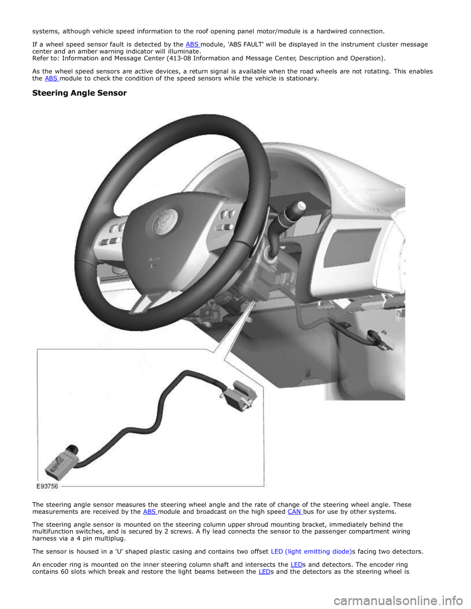
Steering Angle Sensor
The steering angle sensor measures the steering wheel angle and the rate of change of the steering wheel angle. These
measurements are received by the ABS module and broadcast on the high speed CAN bus for use by other systems.
The steering angle sensor is mounted on the steering column upper shroud mounting bracket, immediately behind the
multifunction switches, and is secured by 2 screws. A fly lead connects the sensor to the passenger compartment wiring
harness via a 4 pin multiplug.
The sensor is housed in a 'U' shaped plastic casing and contains two offset LED (light emitting diode)s facing two detectors.
An encoder ring is mounted on the inner steering column shaft and intersects the LEDs and detectors. The encoder ring contains 60 slots which break and restore the light beams between the LEDs and the detectors as the steering wheel is
Page 703 of 3039
Published: 09-Jul-2014
Anti-Lock Control - Stability Assist - Anti-Lock Control - Stability Assist
Diagnosis and Testing
Principle of Operation
For a detailed description of the Anti-Lock Control - Stability Assist system, refer to the relevant Description and Operation
sections in the workshop manual. REFER to: (206-09 Anti-Lock Control - Stability Assist)
Anti-Lock Control - Stability Assist (Description and Operation), Anti-Lock Control - Stability Assist (Description and Operation), Anti-Lock Control - Stability Assist (Description and Operation).
Inspection and Verification
CAUTION: Diagnosis by substitution from a donor vehicle is NOT acceptable. Substitution of control modules does not
guarantee confirmation of a fault, and may also cause additional faults in the vehicle being tested and/or the donor vehicle.
1. Verify the customer concern.
2. Confirm if the Anti-Lock Brake System (ABS) warning light was illuminated, or still is.
NOTE: An intermittent fault may allow the warning light to go off. This does not necessarily mean the fault is not
present. Some warnings will appear to clear when the ignition is cycled. This is often because the warning has flagged as a
result of one of the vehicle's on-board diagnostic routines having run to detect the fault. If the same routine is not run when
the ignition status is set to ON, the warning will not re-flag until the routine does run.
3. Visually inspect for obvious signs of damage and system integrity.
Visual Inspection
Mechanical Electrical
Brake fluid level
Vacuum system
Wheel speed sensor installation
Wheel speed sensor air gap
Magnetic pulse wheel(s) (damaged/contaminated)
Steering angle sensor
Yaw rate sensor and accelerometer cluster installation
Incorrect wheel or tire size
Warning light operation
Fuses
Wheel speed sensors
Connectors/Pins
Harnesses
Steering wheel rotation sensor
Yaw rate sensor and accelerometer cluster
Booster pressure sensor
Hydraulic Control Unit (HCU)
4. If an obvious cause for an observed or reported concern is found, correct the cause (if possible) before proceeding to
the next step.
5. If the cause is not visually evident check for Diagnostic Trouble Codes (DTCs) and refer to the DTC Index.
DTC Index
For a list of Diagnostic Trouble Codes (DTCs) that could be logged on this vehicle, please refer to Section 100-00.
REFER to: Diagnostic Trouble Code (DTC) Index - DTC: Anti-Lock Braking System (ABS) (100-00 General Information, Description and Operation).
Page 1177 of 3039
Fuel Charging and Controls - V8 S/C 5.0L Petrol -
WARNINGS: Published: 11-May-2011
Do not smoke or carry lighted tobacco or open flame of any type when working on or near any fuel related components.
Highly flammable vapors are always present and may ignite. Failure to follow these instructions may result in personal injury.
Before any work is carried out on the fuel system, ground the vehicle to earth and maintain the ground connection until
the work is complete.
CAUTION: Before disconnecting or removing components, make sure the area around the joint faces and connections are
clean. Plug open connections to prevent contamination.
NOTE: Tighten the fuel rail high pressure fuel pump fuel line unions and fuel rail crossover pipe unions as it is instructed
in service manual.
Description Nm lb-ft lb-in Ignition coil-on-plugs retaining bolts 7 - 62 Spark plugs 20 15 - Fuel rail retaining bolt Stage 1 - 20 Stage 2 - 30 Stage 1 - 15 Stage 2 - 22 - Fuel rail crossover pipe unions 21 15 - Fuel rail crossover pipe retaining bolts 12 9 - Fuel pressure regulator 33 24 - Fuel rail high pressure fuel pump fuel line unions 21 15 - Fuel rail high pressure fuel pump fuel line M8 bolt 25 18 - Fuel rail high pressure fuel pump fuel line M6 bolt 11 8 - Fuel rail high pressure fuel pump fuel line M5 nut 6 - 53 Fuel rail high pressure fuel pump fuel line shield M10 bolt 29 21 - Fuel rail high-pressure fuel pump fuel line shield M6 bolt 11 8 - Fuel rail high pressure fuel pump torx bolts 12 9 - Throttle body retaining bolts 10 7 - Accessory drive belt idler pulley retaining bolts 25 18 - Steering gear retaining bolts 100 74 - Steering column lower universal joint assembly bolts 35 26 - Coolant expansion tank retaining bolt 10 7 - Engine compartment brace retaining bolts 45 33 - www.JagDocs.com
Page 1189 of 3039
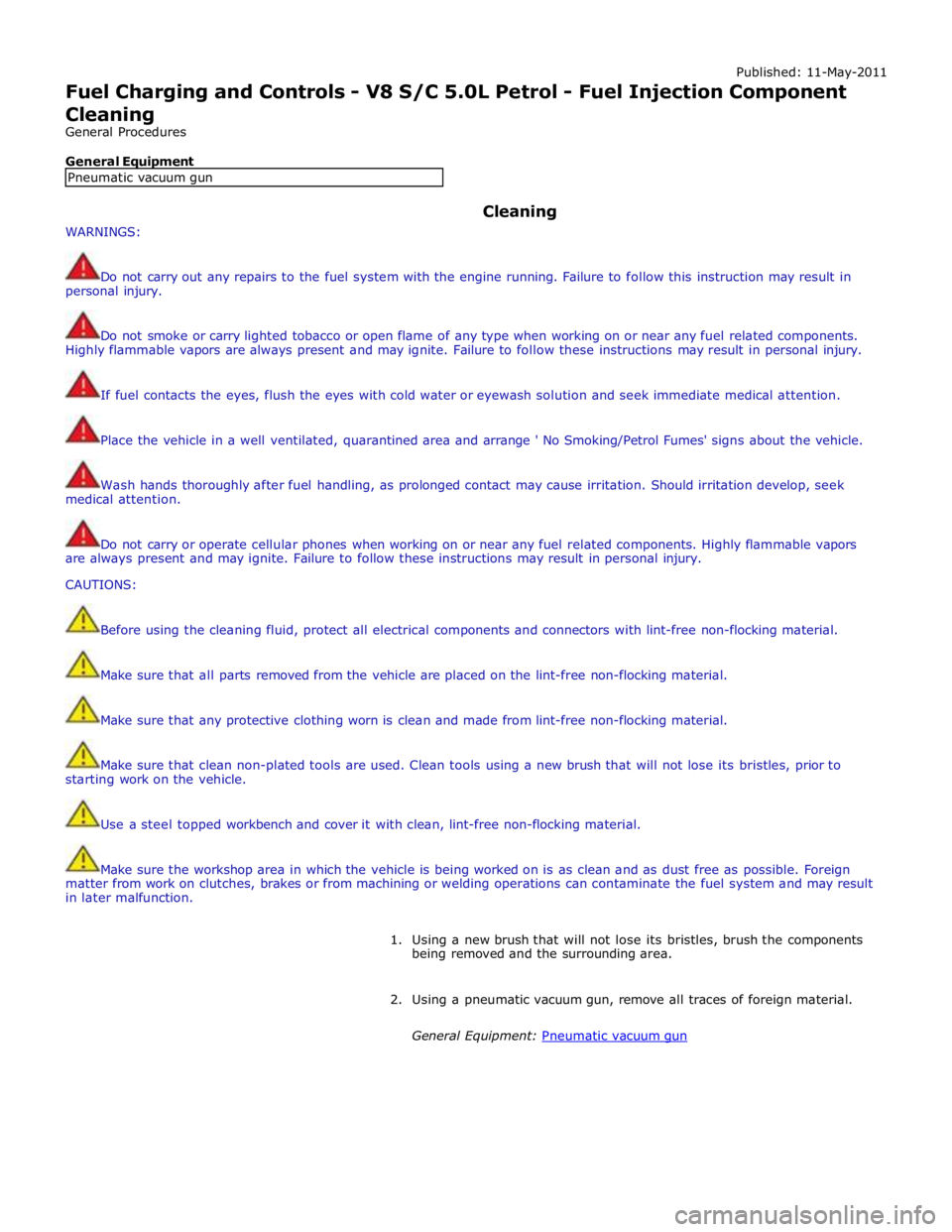
Published: 11-May-2011
Fuel Charging and Controls - V8 S/C 5.0L Petrol - Fuel Injection Component Cleaning
General Procedures
General Equipment
WARNINGS: Cleaning
Do not carry out any repairs to the fuel system with the engine running. Failure to follow this instruction may result in
personal injury.
Do not smoke or carry lighted tobacco or open flame of any type when working on or near any fuel related components.
Highly flammable vapors are always present and may ignite. Failure to follow these instructions may result in personal injury.
If fuel contacts the eyes, flush the eyes with cold water or eyewash solution and seek immediate medical attention.
Place the vehicle in a well ventilated, quarantined area and arrange ' No Smoking/Petrol Fumes' signs about the vehicle.
Wash hands thoroughly after fuel handling, as prolonged contact may cause irritation. Should irritation develop, seek
medical attention.
Do not carry or operate cellular phones when working on or near any fuel related components. Highly flammable vapors
are always present and may ignite. Failure to follow these instructions may result in personal injury.
CAUTIONS:
Before using the cleaning fluid, protect all electrical components and connectors with lint-free non-flocking material.
Make sure that all parts removed from the vehicle are placed on the lint-free non-flocking material.
Make sure that any protective clothing worn is clean and made from lint-free non-flocking material.
Make sure that clean non-plated tools are used. Clean tools using a new brush that will not lose its bristles, prior to
starting work on the vehicle.
Use a steel topped workbench and cover it with clean, lint-free non-flocking material.
Make sure the workshop area in which the vehicle is being worked on is as clean and as dust free as possible. Foreign
matter from work on clutches, brakes or from machining or welding operations can contaminate the fuel system and may result
in later malfunction.
1. Using a new brush that will not lose its bristles, brush the components
being removed and the surrounding area.
2. Using a pneumatic vacuum gun, remove all traces of foreign material.
General Equipment: Pneumatic vacuum gun Pneumatic vacuum gun