Dtc JAGUAR XFR 2010 1.G Workshop Manual
[x] Cancel search | Manufacturer: JAGUAR, Model Year: 2010, Model line: XFR, Model: JAGUAR XFR 2010 1.GPages: 3039, PDF Size: 58.49 MB
Page 468 of 3039
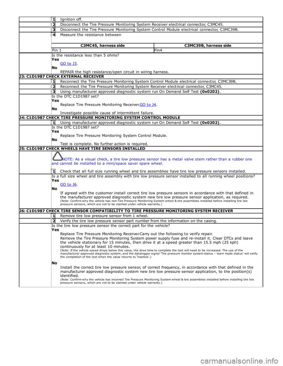
1 Ignition off. 2 Disconnect the Tire Pressure Monitoring System Receiver electrical connector, C3MC45. 3 Disconnect the Tire Pressure Monitoring System Control Module electrical connector, C3MC39B. 4 Measure the resistance between C3MC45, harness side C3MC39B, harness side Pin 1 Pin4 Is the resistance less than 5 ohms? Yes
GO to J3. No
REPAIR the high resistance/open circuit in wiring harness. J3: C1D1987 CHECK EXTERNAL RECEIVER 1 Reconnect the Tire Pressure Monitoring System Control Module electrical connector, C3MC39B. 2 Reconnect the Tire Pressure Monitoring System Receiver electrical connector, C3MC45. 3 Using manufacturer approved diagnostic system run On Demand Self Test (0x0202). Is the DTC C1D1987 set? Yes
Replace Tire Pressure Monitoring Receiver.GO to J4. No
Investigate possible cause of intermittent failure. J4: C1D1987 CHECK TIRE PRESSURE MONITORING SYSTEM CONTROL MODULE 1 Using manufacturer approved diagnostic system run On Demand Self Test (0x0202). Is the DTC C1D1987 set? Yes
Replace Tire Pressure Monitoring System Control Module.
No
Test is complete. No further action is required. J5: C1D1987 CHECK WHEELS HAVE TIRE SENSORS INSTALLED
NOTE: As a visual check, a tire low pressure sensor has a metal valve stem rather than a rubber one
and cannot be installed to a mini/space saver spare wheel. 1 Check that all full size running wheel and tire assemblies have tire low pressure sensors installed. Is a full size wheel and tire assembly with tire low pressure sensor installed to all running wheel positions? Yes
GO to J6. No
If agreed with the customer install correct tire low pressure sensors in accordance with that defined in
the manufacturer approved diagnostic system new tire low pressure sensor application, as required.
(Note: Confirm why the vehicle has non-Tire Pressure Monitoring System w he e l & tire assemblies installed before installing tire low
pressure sensors, which are not to be claimed under vehicle warranty.) J6: C1D1987 CHECK TIRE SENSOR COMPATIBILITY TO TIRE PRESSURE MONITORING SYSTEM RECEIVER 1 Remove tire low pressure sensor from 1 wheel. 2 Verify the tire low pressure sensor part number from the information on the casing. Is the tire low pressure sensor the correct part for the vehicle? Yes
Replace Tire Pressure Monitoring Receiver.Carry out the following to verify repair.
Remove the Tire Pressure Monitoring System power supply fuse and re-install it. Clear DTCs and leave
the vehicle stationary for 15 minutes, then drive it at a speed greater than 15.5 mph (25 kph)
continuously for at least 10 minutes.
(Note: If the vehicle spe e d drops below this value, the drive time to complete the test will need to be increased. The use of the manufacturer approved diagnostic system, and the datalogger signal ’Tire pressure monitor system status – learn mode status’ will verify the completion of the test w he n the value returns to ‘Inactive’.)
No
Install the correct tire low pressure sensor, of correct frequency, in accordance with that defined in the
manufacturer approved diagnostic system new tire low pressure sensor application, to the position(s)
identified.
(Note: Confirm why the vehicle has incorrect Tire Pressure Monitoring System w he e l & tire assemblies installed before installing tire low
pressure sensors, which are not to be claimed under vehicle warranty.)
Page 484 of 3039
each damper to the appropriate level to maintain a flat and level body.
Roll Rate Control – Uses CAN inputs. Predicts vehicle roll rate due to driver steering inputs 100 times a second and increases damping to reduce roll rate.
Pitch Rate Control – Uses CAN inputs. Predicts vehicle pitch rate due to driver throttle and braking inputs 100 times a second and increases damping to reduce pitch rate.
Bump Rebound Control – Uses suspension height sensor and CAN inputs. Monitors the position of the wheel 500 times a second and increases the damping rate as the damper approaches the end of its travel.
Wheel Hop Control – Uses suspension height sensor and CAN inputs. Monitors the position of the wheel 500 times a second and detects when the wheel is at its natural frequency and increases the dampingto reduce vertical wheel
motion.
Under normal road conditions when the vehicle is stationary with the engine running, the dampers are set to the firm condition
to reduce power consumption.
The adaptive damping module receives its power supply via a relay and fuse in the CJB. The relay remains energized for a period of time after the ignition is off. This allows the adaptive damping module to record and store any DTC (diagnostic
trouble code) relating to adaptive dynamics system faults.
DAMPERS Component Description
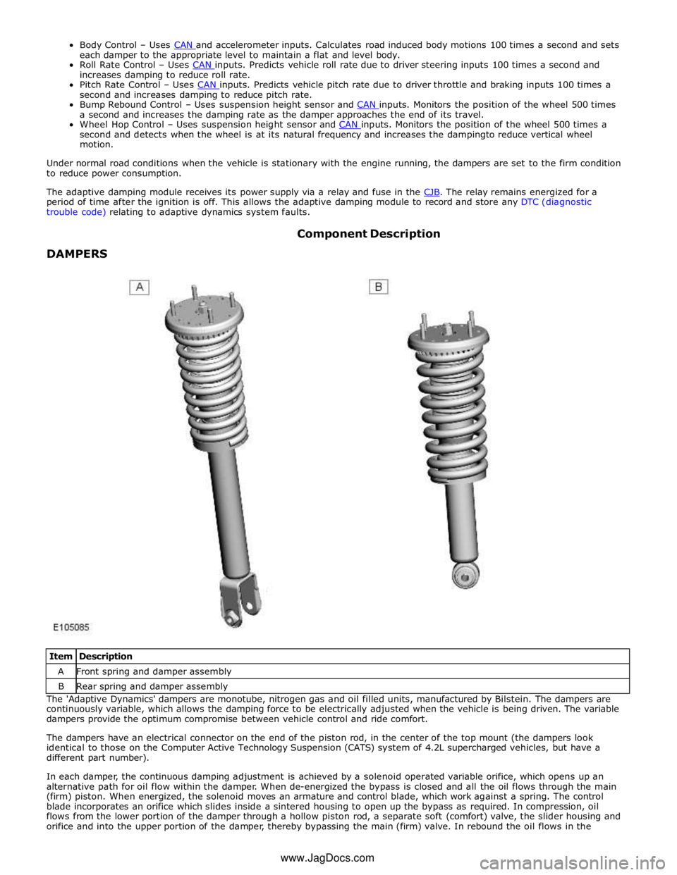
Item Description A Front spring and damper assembly B Rear spring and damper assembly The 'Adaptive Dynamics' dampers are monotube, nitrogen gas and oil filled units, manufactured by Bilstein. The dampers are
continuously variable, which allows the damping force to be electrically adjusted when the vehicle is being driven. The variable
dampers provide the optimum compromise between vehicle control and ride comfort.
The dampers have an electrical connector on the end of the piston rod, in the center of the top mount (the dampers look
identical to those on the Computer Active Technology Suspension (CATS) system of 4.2L supercharged vehicles, but have a
different part number).
In each damper, the continuous damping adjustment is achieved by a solenoid operated variable orifice, which opens up an
alternative path for oil flow within the damper. When de-energized the bypass is closed and all the oil flows through the main
(firm) piston. When energized, the solenoid moves an armature and control blade, which work against a spring. The control
blade incorporates an orifice which slides inside a sintered housing to open up the bypass as required. In compression, oil
flows from the lower portion of the damper through a hollow piston rod, a separate soft (comfort) valve, the slider housing and
orifice and into the upper portion of the damper, thereby bypassing the main (firm) valve. In rebound the oil flows in the www.JagDocs.com
Page 487 of 3039
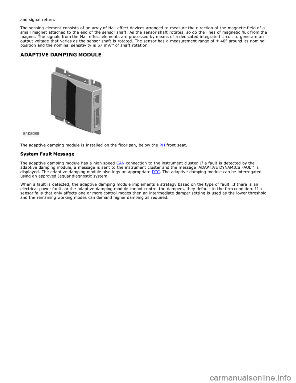
System Fault Message
The adaptive damping module has a high speed CAN connection to the instrument cluster. If a fault is detected by the adaptive damping module, a message is sent to the instrument cluster and the message 'ADAPTIVE DYNAMICS FAULT' is
displayed. The adaptive damping module also logs an appropriate DTC. The adaptive damping module can be interrogated using an approved Jaguar diagnostic system.
When a fault is detected, the adaptive damping module implements a strategy based on the type of fault. If there is an
electrical power fault, or the adaptive damping module cannot control the dampers, they default to the firm condition. If a
sensor fails that only affects one or more control modes then an intermediate damper setting is used as the lower threshold
and the remaining working modes can demand higher damping as required.
Page 488 of 3039

Vehicle Dynamic Suspension - Vehicle Dynamic Suspension
Diagnosis and Testing
Principle of Operation Published: 09-Jul-2014
For a detailed description of the adaptive damping system operation, refer to the relevant Description and Operation section of
the workshop manual. REFER to: (204-05 Vehicle Dynamic Suspension)
Vehicle Dynamic Suspension - V8 5.0L Petrol/V8 S/C 5.0L Petrol (Description and Operation),
Inspection and Verification
1. Verify the customer concern.
2. Visually inspect for obvious signs of damage and system integrity.
Visual Inspection
Mechanical Electrical
Coil spring(s)
Shock absorber(s)
Accelerometer(s) installation
Height sensor(s) installation
Fuse(s)
Wiring harness/electrical connectors
Accelerometer(s)
Adaptive Damping Control Module
Height sensor(s)
3. If an obvious cause for an observed or reported concern is found, correct the cause (if possible) before proceeding to
the next step.
4. If the cause is not visually evident, check the system for any logged Diagnostic Trouble Codes (DTCs) and refer to the
DTC index.
DTC Index
For a list of Diagnostic Trouble Codes (DTCs) that could be logged on this vehicle, please refer to Section 100-00.
REFER to: Diagnostic Trouble Code (DTC) Index - DTC: Adaptive Damping Module (SUMB) (100-00 General Information, Description and Operation).
Page 538 of 3039
Rear Drive Axle/Differential - Rear Drive Axle and Differential
Diagnosis and Testing
Principle of Operation Published: 12-May-2014
For a detailed description of the Rear Drive Axle and Differential, refer to the relevant Description and Operation section in the
workshop manual. REFER to: Rear Drive Axle and Differential (205-02 Rear Drive Axle/Differential, Description and Operation).
Inspection and Verification
CAUTION: Diagnosis by substitution from a donor vehicle is NOT acceptable. Substitution of control modules does not
guarantee confirmation of a fault, and may also cause additional faults in the vehicle being tested and/or the donor vehicle.
1. Verify the customer concern.
2. Visually inspect for obvious signs of damage and system integrity.
Mechanical Electrical
Fixings that secure Rear Differential Control Module (Heat path
for Module Heatsink)
Fuses/Relays
Damaged, Loose or Corroded Connector(s)
Damage to Wiring Loom/Incorrect Location,
Stretched or Taught
3. If an obvious cause for an observed or reported concern is found, correct the cause (if possible) before proceeding to
the next step.
4. If the cause is not visually evident, check the system for any logged Diagnostic Trouble Codes (DTCs) and refer to the
DTC index.
DTC Index
For a list of diagnostic trouble codes that could be logged on this vehicle, please refer to Section 100-00. REFER to: Diagnostic Trouble Code (DTC) Index - DTC: Rear Differential Control Module (RDCM) (100-00 General Information, Description and Operation).
Page 653 of 3039
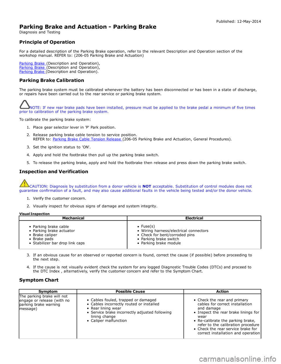
Parking Brake and Actuation - Parking Brake
Diagnosis and Testing
Principle of Operation Published: 12-May-2014
For a detailed description of the Parking Brake operation, refer to the relevant Description and Operation section of the
workshop manual. REFER to: (206-05 Parking Brake and Actuation)
Parking Brake (Description and Operation), Parking Brake (Description and Operation), Parking Brake (Description and Operation).
Parking Brake Calibration
The parking brake system must be calibrated whenever the battery has been disconnected or has been in a state of discharge,
or repairs have been carried out to the rear service or parking brake system.
NOTE: If new rear brake pads have been installed, pressure must be applied to the brake pedal a minimum of five times
prior to calibration of the parking brake system.
To calibrate the parking brake system:
1. Place gear selector lever in 'P' Park position.
2. Release parking brake cable tension to service position.
REFER to: Parking Brake Cable Tension Release (206-05 Parking Brake and Actuation, General Procedures).
3. Set the ignition status to 'ON'.
4. Apply and hold the footbrake then pull up the parking brake switch.
5. To release the parking brake, apply and hold the footbrake then release and press down the parking brake switch.
Inspection and Verification
CAUTION: Diagnosis by substitution from a donor vehicle is NOT acceptable. Substitution of control modules does not
guarantee confirmation of a fault, and may also cause additional faults in the vehicle being tested and/or the donor vehicle.
1. Verify the customer concern.
2. Visually inspect for obvious signs of damage and system integrity.
Visual Inspection
Mechanical Electrical
Parking brake cable
Parking brake actuator
Brake caliper
Brake pads
Stabilizer bar drop link caps
Fuse(s)
Wiring harness/electrical connectors
Check for bent/corroded pins
Parking brake switch
Parking brake module
3. If an obvious cause for an observed or reported concern is found, correct the cause (if possible) before proceeding to
the next step.
4. If the cause is not visually evident check the system for any logged Diagnostic Trouble Codes (DTCs) and proceed to
the DTC Index , alternatively, verify the customer concern and refer to the Symptom Chart.
Symptom Chart
Symptom Possible Cause Action The parking brake will not
engage or release (with no
parking brake warning
message)
Cables fouled, trapped or damaged
Cables incorrectly routed or installed
Rear lining wear
Service brake incorrectly adjusted following
lining change
Caliper malfunction
Check the rear and primary
cables for correct installation
and damage
Inspect the rear brake linings for
wear
Re-calibrate the parking brake,
refer to the calibration procedure
Check the rear service brake for
correct installation and operation
Page 654 of 3039

Symptom Possible Cause Action The parking brake will not
engage or release (with
parking brake warning
message)
Cables fouled, trapped or damaged
Cables incorrectly routed or installed
Rear lining wear
Actuator malfunction
Caliper malfunction
Check the rear and primary
cables for correct installation
and damage
Inspect the rear brake linings for
wear
Re-calibrate the parking brake,
refer to the calibration procedure
Check the rear service brake for
correct installation and operation No communication with the
parking brake module
Fuse
Module off Bus
CAN network error
Parking brake module fault
Check fuses
Ensure battery is fully charged
and in serviceable condition.
Check battery voltage at parking
brake module
Check CAN network using
manufacturer approved
diagnostic system 'Park brake Fault' displayed on
message center with
associated warning lamps
Parking brake system fault
Check the parking brake module
for DTCs and refer to DTC Index Brakes drag
Parking brake not re-calibrated after battery has
been disconnected or has been in a state of
discharge, or repairs have been carried out to
the rear service or parking brake system
Service brake system fault
Re-calibrate parking brake, refer
to the calibration procedure
Check the service brake for
correct operation DTC Index
For a list of diagnostic trouble codes that could be logged on this vehicle, please refer to Section 100-00.
REFER to: Diagnostic Trouble Code (DTC) Index - DTC: Electric Parking Brake (PBM) (100-00 General Information, Description and Operation).
Page 656 of 3039

3. WARNING: Failure to follow this instruction may result in a
diagnostic trouble code (DTC) being generated.
Disconnect the 2 electrical connectors from the parking
brake module, in the sequence illustrated.
4. NOTE: Some variation in the illustrations may occur,
but the essential information is always correct.
Connect the special tool to the parking brake module.
5. Release the parking brake cable tension.
An audible 'click', signals complete parking brake cable
tension release.
6. Remove the special tool and carry out any necessary repairs on the
system.
Page 663 of 3039
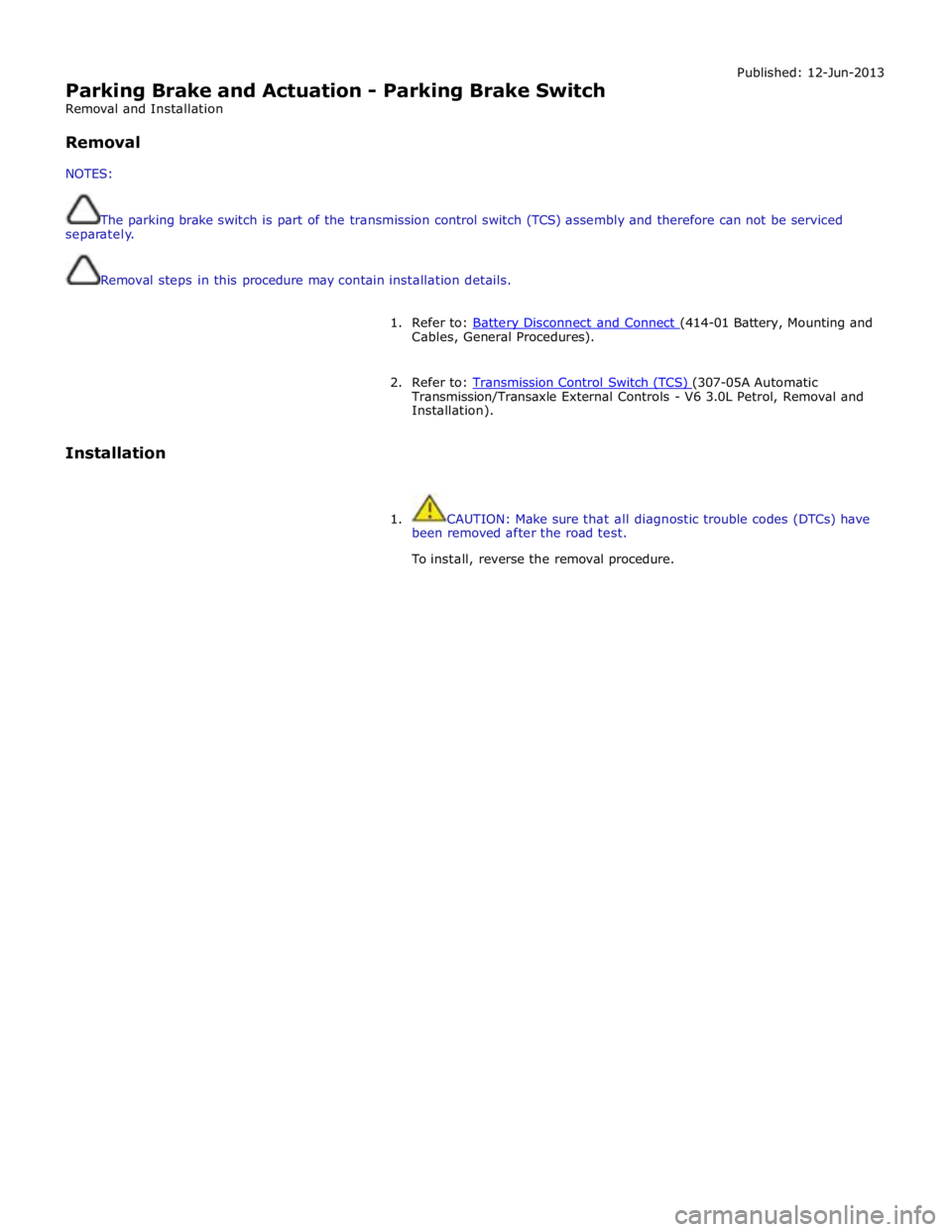
Parking Brake and Actuation - Parking Brake Switch
Removal and Installation
Removal
NOTES: Published: 12-Jun-2013
The parking brake switch is part of the transmission control switch (TCS) assembly and therefore can not be serviced
separately.
Removal steps in this procedure may contain installation details.
1. Refer to: Battery Disconnect and Connect (414-01 Battery, Mounting and Cables, General Procedures).
2. Refer to: Transmission Control Switch (TCS) (307-05A Automatic Transmission/Transaxle External Controls - V6 3.0L Petrol, Removal and
Installation).
Installation
1. CAUTION: Make sure that all diagnostic trouble codes (DTCs) have
been removed after the road test.
To install, reverse the removal procedure.
Page 703 of 3039
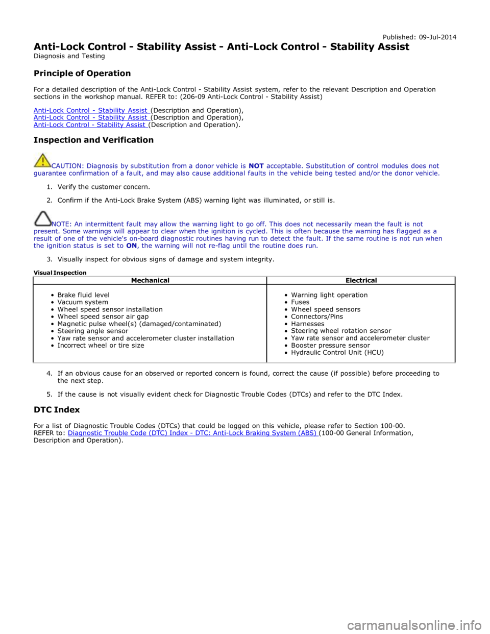
Published: 09-Jul-2014
Anti-Lock Control - Stability Assist - Anti-Lock Control - Stability Assist
Diagnosis and Testing
Principle of Operation
For a detailed description of the Anti-Lock Control - Stability Assist system, refer to the relevant Description and Operation
sections in the workshop manual. REFER to: (206-09 Anti-Lock Control - Stability Assist)
Anti-Lock Control - Stability Assist (Description and Operation), Anti-Lock Control - Stability Assist (Description and Operation), Anti-Lock Control - Stability Assist (Description and Operation).
Inspection and Verification
CAUTION: Diagnosis by substitution from a donor vehicle is NOT acceptable. Substitution of control modules does not
guarantee confirmation of a fault, and may also cause additional faults in the vehicle being tested and/or the donor vehicle.
1. Verify the customer concern.
2. Confirm if the Anti-Lock Brake System (ABS) warning light was illuminated, or still is.
NOTE: An intermittent fault may allow the warning light to go off. This does not necessarily mean the fault is not
present. Some warnings will appear to clear when the ignition is cycled. This is often because the warning has flagged as a
result of one of the vehicle's on-board diagnostic routines having run to detect the fault. If the same routine is not run when
the ignition status is set to ON, the warning will not re-flag until the routine does run.
3. Visually inspect for obvious signs of damage and system integrity.
Visual Inspection
Mechanical Electrical
Brake fluid level
Vacuum system
Wheel speed sensor installation
Wheel speed sensor air gap
Magnetic pulse wheel(s) (damaged/contaminated)
Steering angle sensor
Yaw rate sensor and accelerometer cluster installation
Incorrect wheel or tire size
Warning light operation
Fuses
Wheel speed sensors
Connectors/Pins
Harnesses
Steering wheel rotation sensor
Yaw rate sensor and accelerometer cluster
Booster pressure sensor
Hydraulic Control Unit (HCU)
4. If an obvious cause for an observed or reported concern is found, correct the cause (if possible) before proceeding to
the next step.
5. If the cause is not visually evident check for Diagnostic Trouble Codes (DTCs) and refer to the DTC Index.
DTC Index
For a list of Diagnostic Trouble Codes (DTCs) that could be logged on this vehicle, please refer to Section 100-00.
REFER to: Diagnostic Trouble Code (DTC) Index - DTC: Anti-Lock Braking System (ABS) (100-00 General Information, Description and Operation).