Rke module JAGUAR XFR 2010 1.G Owner's Manual
[x] Cancel search | Manufacturer: JAGUAR, Model Year: 2010, Model line: XFR, Model: JAGUAR XFR 2010 1.GPages: 3039, PDF Size: 58.49 MB
Page 1788 of 3039
gage, odometer, trip distance and trip computer readouts. The trip distance and trip computer information is derived from
information supplied on the high speed CAN bus to the instrument cluster from the ABS module and the ECM.
The area above the message center displays the transmission gear position information and speed control related information.
The transmission information is supplied on the high speed CAN bus from the TCM (transmission control module).
NOTE: There is no engine coolant temperature gage displayed. If the engine coolant temperature increases to above a
predetermined threshold, a warning message is displayed in the message center. The message is sent from the ECM in a high speed CAN message to the instrument cluster.
TRANSMISSION GEAR SELECTION POSITION
The gear position display shows JaguarDrive selector position or selected gear when using the Jaguar Sequential Shift. The gear
selector module transmits a CAN message to the instrument cluster for gear selector lever position. The module also outputs a 'not in park' signal to the instrument cluster. The TCM transmits a high speed CAN message to the instrument cluster with data containing the selected gear when in Jaguar Sequential Shift mode.
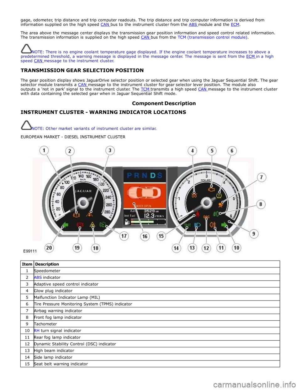
Component Description INSTRUMENT CLUSTER - WARNING INDICATOR LOCATIONS
NOTE: Other market variants of instrument cluster are similar.
EUROPEAN MARKET - DIESEL INSTRUMENT CLUSTER
Item Description 1 Speedometer 2 ABS indicator 3 Adaptive speed control indicator 4 Glow plug indicator 5 Malfunction Indicator Lamp (MIL) 6 Tire Pressure Monitoring System (TPMS) indicator 7 Airbag warning indicator 8 Front fog lamp indicator 9 Tachometer 10 RH turn signal indicator 11 Rear fog lamp indicator 12 Dynamic Stability Control (DSC) indicator 13 High beam indicator 14 Side lamp indicator 15 Seat belt warning indicator
Page 1789 of 3039

17 Automatic Speed Limiter (ASL) indicator 18 Forward alert indicator 19 Brake warning indicator 20 LH turn signal indicator NAS MARKET - V8 NORMALLY ASPIRATED INSTRUMENT CLUSTER
Item Description 1 Speedometer 2 ABS indicator (NAS) 3 ABS indicator (ROW) 4 Adaptive speed control indicator 5 Tachometer 6 Malfunction Indicator Lamp (MIL) 7 Tire Pressure Monitoring System (TPMS) indicator 8 Airbag warning indicator 9 Front fog lamp indicator 10 RH turn signal indicator 11 Rear fog lamp indicator 12 Dynamic Stability Control (DSC) indicator 13 High beam indicator 14 Seat belt warning indicator 15 Side lamp indicator 16 Message center 17 Automatic Speed Limiter (ASL) indicator 18 Forward alert indicator 19 Brake warning indicator (NAS) 20 Brake warning indicator (ROW) 21 LH turn signal indicator The warning indicators are located in various positions in the instrument cluster. The indicators can be split into two groups;
instrument cluster controlled and externally controlled.
Instrument cluster controlled warning indicators are dependent on software logic within the instrument cluster for activation.
The cluster software controls the indicator illumination check at ignition on (power mode 6).
Externally controlled indicators are supplied with current from another vehicle system control module or illuminated by the
instrument cluster software on receipt of a bus message from another vehicle sub-system. The indicator illumination check at
ignition on (powermode 6) is also controlled by the sub-system module for these indicators.
Page 1799 of 3039

DTC Description Possible Cause Action B100C67
Column Lock
Supply
Authorisation
Instrument cluster power and
ground supply circuits - short,
open circuit
LS CAN fault
CJB power and ground supply
circuits - short, open circuit
Vehicle speed present when
attempting to power ESCL
Engine speed present when
attempting to power ESCL
PowerMode status > 4 when
attempting to perform lock
action Carry out any pinpoint tests associated with this DTC using
the manufacturer approved diagnostic system. Refer to the
electrical circuit diagrams and check CJB power and ground
supply circuits for short, open circuit and instrument cluster
power and ground supply circuits for short, open circuit.
Check CAN communications between CJB and instrument
cluster. Check for invalid vehicle speed signal from
ABS/instrument cluster gateway. Check for invalid engine
speed signal from ECM/instrument cluster gateway. Check for
invalid signal from CJB B100C87
Column Lock
Supply
Authorisation
Instrument cluster power and
ground supply circuits - short,
open circuit
LS CAN fault
CJB power and ground supply
circuits - short, open circuit Carry out any pinpoint tests associated with this DTC using
the manufacturer approved diagnostic system. Refer to the
electrical circuit diagrams and check CJB power and ground
supply circuits for short, open circuit and instrument cluster
power and ground supply circuits for short, open circuit.
Check CAN communications between CJB and instrument
cluster B100D62
Column Lock
Authorisation
CAN fault
ESCL power and ground supply
circuits - short, open circuit
Instrument cluster power and
ground supply circuits - short,
open circuit
Incorrect ESCL or instrument
cluster installed
Target SID synchronization
error following re-programming
Noise/EMC related error Carry out any pinpoint tests associated with this DTC using
the manufacturer approved diagnostic system. Check CAN
communication between Electronic Steering Column Lock and
instrument cluster. Refer to the electrical circuit diagrams
and check Electronic Steering Column Lock power and ground
supply circuits for short, open circuit and Instrument cluster
power and ground supply circuits for short, open circuit.
Check correct Electronic Steering Column Lock and instrument
cluster installed. Perform the Immobilisation application from
the Set-up menu using the manufacturer approved diagnostic
system. Check CAN network for interference/EMC related
issues B100D64
Column Lock
Authorisation
Algorithm based failure-signal
plausibility failure
CAN fault
ESCL power and ground supply
circuits - short, open circuit
Instrument cluster power and
ground supply circuits - short,
open circuit If the customer has not reported a non start issue, clear the
DTC and check vehicle starts correctly. If a non start issue
has been reported run the manufacturers approved
diagnostic system Start Authorisation Application and follow
the actions required for this DTC. Carry out any pinpoint
tests associated with this DTC using the manufacturer
approved diagnostic system. Check CAN communication
between Electronic Steering Column Lock and instrument
cluster (check transmission out speed, vehicle speed, engine
speed, gear position and powermode signals to Electronic
Steering Column Lock). Refer to the electrical circuit
diagrams and check Electronic Steering Column Lock power
and ground supply circuits for short, open circuit and
Instrument cluster power and ground supply circuits for
short, open circuit. B100D87
Column Lock
Authorisation -
Missing message
Missing message
CAN fault
No response from electric
steering column lock control
module, instrument cluster,
central junction box Battery
voltage at electric
steering column lock control
module too low
Electric steering column lock
control module, instrument
cluster, central junction box
fault
Clear DTC, repeatedly lock and unlock car using the
key fob and retest. Check for related DTCs and refer
to the relevant DTC index
If the fault is cleared, notify the customer that the
steering column lock may fail to unlock if the vehicle
is parked with a high steering angle or with the road
wheel against a curb. If the column lock is failing to
disengage, the customer may be able to rectify this
by rotating the steering wheel while pressing the
engine start button
If fault persists, complete a CAN network integrity
test using the manufacturers approved diagnostic
system. Alternatively, refer to the electrical circuit
diagrams and check CAN circuits between the central
junction box, the instrument cluster and the
electronic steering column lock. Refer to the electrical
circuit diagrams and check the central junction box,
the instrument cluster and the electronic steering
column lock power and ground supply circuits for short
circuit to ground, short circuit to power, open circuit,
high resistance. Repair circuit(s) as required. Clear
DTC, perform an on demand self-test and retest
If fault persists, check that the vehicle battery supply
voltage is between 9-16 volts. Rectify as required
Page 1800 of 3039

DTC Description Possible Cause Action B100D96
Column Lock
Authorisation -
Component
internal failure
Battery voltage at electric
steering column lock control
module too low
Torque load on steering
column
CAN fault
Electric steering column lock
control module - Internal
failure
Clear DTC, repeatedly lock and unlock car using the
key fob and retest
If fault persists, check that the vehicle battery supply
voltage is between 9-16 volts. Rectify as required
Ensure the column lock bolt movement is not
obstructed or restricted (the parked position of the
road wheels may be exerting a turning force through
the steering column, preventing the lock from
releasing. The steering wheel may need to be held
against the force to allow the column lock to
release). Clear DTC, repeatedly lock and unlock car
using the key fob and retest
If fault persists, complete a CAN network integrity
test using the manufacturers approved diagnostic
system. Alternatively, refer to the electrical circuit
diagrams and check CAN circuits between the central
junction box, the instrument cluster and the
electronic steering column lock. Refer to the electrical
circuit diagrams and check the central junction box,
the instrument cluster and the electronic steering
column lock power and ground supply circuits for short
circuit to ground, short circuit to power, open circuit,
high resistance. Repair circuit(s) as required. Clear
DTC, perform an on demand self-test and retest
If fault persists, check and install a new electric
steering column lock control module as required B102487 Start Control Unit
Smart card docking station
failure - slave node not
responding Carry out any pinpoint tests associated with this DTC using
the manufacturer approved diagnostic system. Refer to the
electrical circuit diagrams and check the smart card docking
station LIN circuit for short, open circuit. Suspect the smart
card docking station, check and install a new docking station
as required, refer to the new module/component installation
note at the top of the DTC Index B104611
Front Fog Lamp
Control Switch
Fog lamp switch circuit - short
to ground Refer to the electrical circuit diagrams and check fog lamp
switch circuit for short to ground B104615
Front Fog Lamp
Control Switch
Fog lamp switch circuit - short
to power, open circuit Refer to the electrical circuit diagrams and check fog lamp
switch circuit for short to power, open circuit B104811
Brake Fluid Level
Switch
Brake fluid level switch circuit
- short to ground Refer to the electrical circuit diagrams and check brake fluid
level switch circuit for short to ground B10A011
Wiper/ Washer
Switch
Wash/wipe circuit - short to
ground Refer to the electrical circuit diagrams and check wash/wipe
circuit for short to ground B10A015
Wiper/ Washer
Switch
Wash/wipe circuit - short to
power, open circuit Carry out any pinpoint tests associated with this DTC using
the manufacturer approved diagnostic system. Refer to the
electrical circuit diagrams and check wash/wipe circuit for
short to power, open circuit B10A611 Main Light Switch
Master lighting switch circuit -
short to ground Refer to the electrical circuit diagrams and check master
lighting switch circuit for short to ground B10A615 Main Light Switch
Master lighting switch circuit -
short to power, open circuit Carry out any pinpoint tests associated with this DTC using
the manufacturer approved diagnostic system. Refer to the
electrical circuit diagrams and check master lighting switch
circuit for short to power, open circuit B112B87
Steering Wheel
Module
Steering wheel module failure
- slave node not responding Carry out any pinpoint tests associated with this DTC using
the manufacturer approved diagnostic system. Refer to the
electrical circuit diagrams and check the clockspring LIN
circuit for short, open circuit. Suspect the clockspring, check
and install a new clockspring as required, refer to the new
module/component installation note at the top of the DTC
Index B115C7A
Transfer Fuel
Pump
Fuel pump system fault Check for fuel system jet pump or jet pump fuel level sensor
fault B1A8515
Ambient Light
Sensor
Autolamp sensor circuit - short
to power, open circuit Carry out any pinpoint tests associated with this DTC using
the manufacturer approved diagnostic system. Refer to the
electrical circuit diagrams and check autolamp sensor circuit
for short to power, open circuit
Page 1824 of 3039
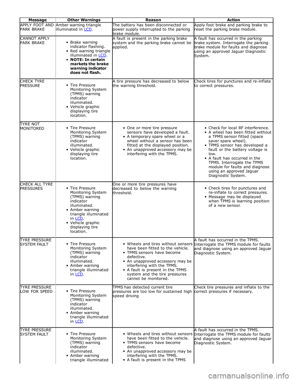
Message Other Warnings Reason Action APPLY FOOT AND
PARK BRAKE Amber warning triangle
illuminated in LCD. The battery has been disconnected or
power supply interrupted to the parking
brake module. Apply foot brake and parking brake to
reset the parking brake module. CANNOT APPLY
PARK BRAKE
Brake warning
indicator flashing.
Red warning triangle
illuminated in LCD. NOTE: In certain
markets the brake
warning indicator
does not flash. A fault is present in the parking brake
system and the parking brake cannot be
applied. A fault has occurred in the parking
brake system. Interrogate the parking
brake module for faults and diagnose
using an approved Jaguar Diagnostic
System. CHECK TYRE
PRESSURE
Tire Pressure
Monitoring System
(TPMS) warning
indicator
illuminated.
Vehicle graphic
displaying tire
location. A tire pressure has decreased to below
the warning threshold. Check tires for punctures and re-inflate
to correct pressures. TYRE NOT
MONITORED
Tire Pressure
Monitoring System
(TPMS) warning
indicator
illuminated.
Vehicle graphic
displaying tire
location.
One or more tire pressure
sensors have developed a fault.
A temporary spare wheel or a
wheel without a sensor has been
fitted at the displayed position.
An unapproved accessory may be
interfering with the TPMS.
Check for local RF interference.
A wheel has been fitted without
a TPMS sensor fitted (space
saver spare wheel).
TPMS sensor has developed a
fault or the battery voltage is
low.
A fault has occurred in the
TPMS. Interrogate the TPMS
module for faults and diagnose
using an approved Jaguar
Diagnostic System. CHECK ALL TYRE
PRESSURES
Tire Pressure
Monitoring System
(TPMS) warning
indicator
illuminated.
Amber warning
triangle illuminated
in LCD. Vehicle graphic
displaying tire
location. One or more tire pressures have
decreased to below the warning
threshold.
Check tires for punctures and
re-inflate to correct pressures.
Message may be displayed
when TPMS is learning position
of a new sensor. TYRE PRESSURE
SYSTEM FAULT
Tire Pressure
Monitoring System
(TPMS) warning
indicator
illuminated.
Amber warning
triangle illuminated
in LCD.
Wheels and tires without sensors
have been fitted to the vehicle.
TPMS sensors have become
defective.
An unapproved accessory may be
interfering with the TPMS.
A fault is present in the TPMS
system and the tire pressures
cannot be monitored. A fault has occurred in the TPMS.
Interrogate the TPMS module for faults
and diagnose using an approved Jaguar
Diagnostic System. TYRE PRESSURE
LOW FOR SPEED
Tire Pressure
Monitoring System
(TPMS) warning
indicator
illuminated.
Amber warning
triangle illuminated
in LCD. TPMS has detected current tire
pressures are too low for sustained high
speed driving Check tire pressures and inflate to the
correct pressures if necessary. TYRE PRESSURE
SYSTEM FAULT
Tire Pressure
Monitoring System
(TPMS) warning
indicator
illuminated.
Amber warning
triangle illuminated
Wheels and tires without sensors
have been fitted to the vehicle.
TPMS sensors have become
defective.
An unapproved accessory may be
interfering with the TPMS.
A fault is present in the TPMS A fault has occurred in the TPMS.
Interrogate the TPMS module for faults
and diagnose using an approved Jaguar
Diagnostic System.
Page 1866 of 3039
Published: 07-Aug-2014
Battery and Charging System - General Information - Battery Care
Requirements
Description and Operation
1. INTRODUCTION
This document defines the requirements for care and maintenance of batteries, and the standard of battery care at dealers and
retailers for new vehicles.
This applies to all types of 12 Volt Lead Acid Batteries used in Jaguar and Land Rover vehicles whether they are conventional
flooded technology or Absorbed Glass Mat (AGM – also known as Valve Regulated Lead Acid (VRLA)) technology and also
applies to both Primary, Secondary and Auxiliary Batteries. AGM batteries offer improved resistance to cycling as seen in stop
start applications.
In order to prevent damage to the battery and ensure a satisfactory service life, all processes detailed within this document
must be rigorously adhered to.
It is equally important therefore to note the following key points:
All new vehicles leave the factory with either a transit relay installed and/or have a transit mode programmed into the
vehicle control modules. The transit relay must be removed and the transit mode disabled (where applicable) using an
approved diagnostic system, NOT MORE THAN 72 HOURS before the customer takes delivery.
The battery can be discharged by the following mechanisms:
- Self Discharge: - A lead acid battery will very slowly discharge itself due to its own internal chemical processes
whether it is connected to a vehicle or not.
- Quiescent Discharge: - The vehicle electrical systems when connected to the battery will draw charge from the
battery.
12 Volt Lead Acid Batteries rely on internal chemical processes to create a voltage and deliver current. These processes and
the internal chemical structure of the battery can be damaged if the battery is allowed to discharge over a number of weeks /
months, or is left in a discharged state for a lengthy time period.
On vehicles with conventional ignition keys, these must not be left in the ignition lock barrel when the transit relay
has been removed, otherwise quiescent current will increase and the battery will discharge more rapidly.
For keyless vehicles, the Smart Key must be stored at least 5m (16 ft) away from the vehicle when the vehicle is
parked or stored.
AGM Batteries are fully sealed and cannot have the electrolyte level topped up.
NOTE: Dealers and retailers involved in the storage / handling of vehicles and replacement batteries have a responsibility
to ensure that only a fully charged battery may be processed through the distribution selling chain.
2. GENERAL RULES FOR BATTERY CARE
2.1 Dealer Demonstration Vehicles
Vehicles used as dealer demonstrator(s), in a showroom, must be connected to a JLR approved showroom conditioner capable
of delivering 50 Amps. This will prevent the battery from being damaged.
2.2 Software Reflash, SDD work or Ignition On related workshop activities
Due to the high electrical current demand and high depth of discharge that can occur during vehicle software re-flash activities,
SDD work or ignition on (power mode 6) related work in the workshop, vehicles that are undergoing such activities MUST have a
JLR approved power supply capable of delivering 50 Amps or more.
2.3 Extended Vehicle Rework
For any extended vehicle rework that results in consuming vehicle power, either the battery should be disconnected or a JLR
approved power supply connected.
2.4 Jump Starting New vehicles before they have been delivered to the customer
It is the dealer / retailers responsibility to make sure the battery is not allowed to discharge by following the
instructions and processes defined in this manual.
However, if circumstances dictate that a new vehicle must be jump started due to a discharged battery whilst the
vehicle is in the dealer / retailers care, the battery on this vehicle must be replaced with a new one prior to delivery
to the customer at the dealer / retailers liability.
The vehicle should also undergo investigation as to why the battery became discharged.
Do not connect the jump starting cable to the negative (-) terminal of the battery. Always connect to the recommended
earth point. As defined in the owners handbook or service documentation for that vehicle. 2.5 AGM Batteries
AGM batteries must not be charged above 14.8 Volts. Doing so will damage them.
AGM Batteries must be tested with a capable battery tester as detailed in the Equipment section (Section 5) of this
Page 1930 of 3039
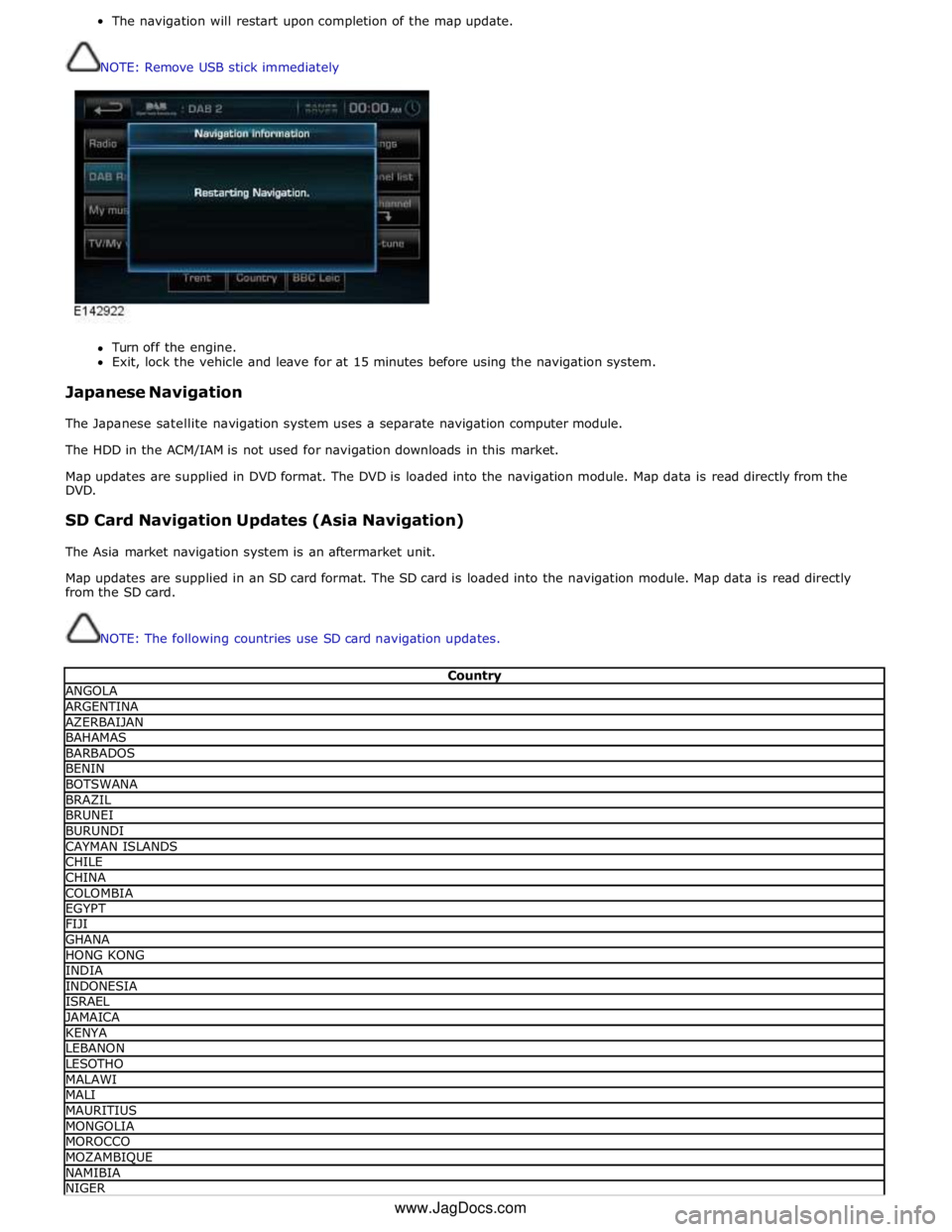
The navigation will restart upon completion of the map update.
NOTE: Remove USB stick immediately
Turn off the engine.
Exit, lock the vehicle and leave for at 15 minutes before using the navigation system.
Japanese Navigation
The Japanese satellite navigation system uses a separate navigation computer module.
The HDD in the ACM/IAM is not used for navigation downloads in this market.
Map updates are supplied in DVD format. The DVD is loaded into the navigation module. Map data is read directly from the
DVD.
SD Card Navigation Updates (Asia Navigation)
The Asia market navigation system is an aftermarket unit.
Map updates are supplied in an SD card format. The SD card is loaded into the navigation module. Map data is read directly
from the SD card.
NOTE: The following countries use SD card navigation updates.
Country ANGOLA ARGENTINA AZERBAIJAN BAHAMAS BARBADOS BENIN BOTSWANA BRAZIL BRUNEI BURUNDI CAYMAN ISLANDS CHILE CHINA COLOMBIA EGYPT FIJI GHANA HONG KONG INDIA INDONESIA ISRAEL JAMAICA KENYA LEBANON LESOTHO MALAWI MALI MAURITIUS MONGOLIA MOROCCO MOZAMBIQUE NAMIBIA NIGER www.JagDocs.com
Page 1936 of 3039
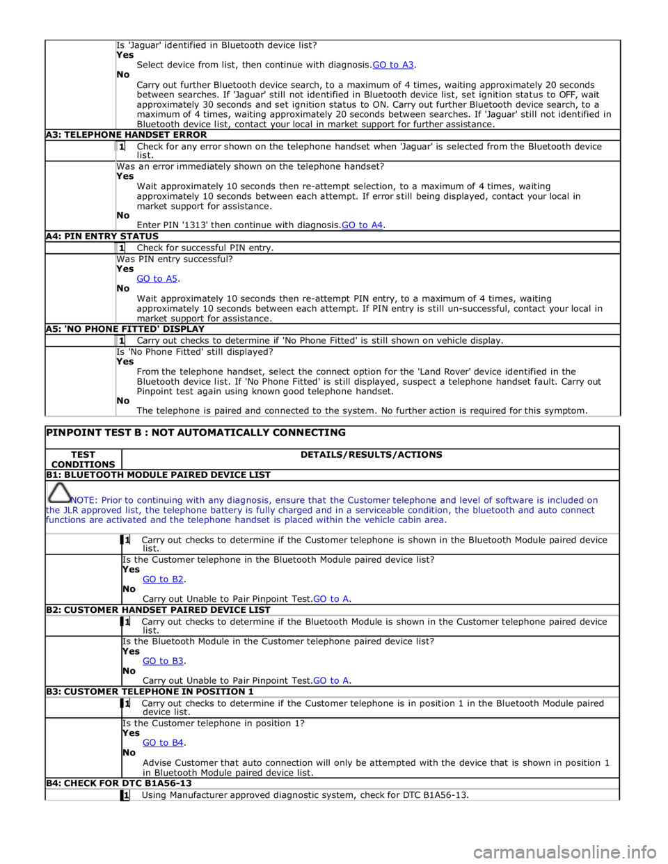
Is 'Jaguar' identified in Bluetooth device list? Yes
Select device from list, then continue with diagnosis.GO to A3. No
Carry out further Bluetooth device search, to a maximum of 4 times, waiting approximately 20 seconds
between searches. If 'Jaguar' still not identified in Bluetooth device list, set ignition status to OFF, wait
approximately 30 seconds and set ignition status to ON. Carry out further Bluetooth device search, to a
maximum of 4 times, waiting approximately 20 seconds between searches. If 'Jaguar' still not identified in
Bluetooth device list, contact your local in market support for further assistance. A3: TELEPHONE HANDSET ERROR 1 Check for any error shown on the telephone handset when 'Jaguar' is selected from the Bluetooth device list. Was an error immediately shown on the telephone handset? Yes
Wait approximately 10 seconds then re-attempt selection, to a maximum of 4 times, waiting
approximately 10 seconds between each attempt. If error still being displayed, contact your local in
market support for assistance.
No
Enter PIN '1313' then continue with diagnosis.GO to A4. A4: PIN ENTRY STATUS 1 Check for successful PIN entry. Was PIN entry successful? Yes
GO to A5. No
Wait approximately 10 seconds then re-attempt PIN entry, to a maximum of 4 times, waiting
approximately 10 seconds between each attempt. If PIN entry is still un-successful, contact your local in
market support for assistance. A5: 'NO PHONE FITTED' DISPLAY 1 Carry out checks to determine if 'No Phone Fitted' is still shown on vehicle display. Is 'No Phone Fitted' still displayed? Yes
From the telephone handset, select the connect option for the 'Land Rover' device identified in the
Bluetooth device list. If 'No Phone Fitted' is still displayed, suspect a telephone handset fault. Carry out
Pinpoint test again using known good telephone handset.
No
The telephone is paired and connected to the system. No further action is required for this symptom.
PINPOINT TEST B : NOT AUTOMATICALLY CONNECTING TEST
CONDITIONS DETAILS/RESULTS/ACTIONS B1: BLUETOOTH MODULE PAIRED DEVICE LIST
NOTE: Prior to continuing with any diagnosis, ensure that the Customer telephone and level of software is included on
the JLR approved list, the telephone battery is fully charged and in a serviceable condition, the bluetooth and auto connect
functions are activated and the telephone handset is placed within the vehicle cabin area. 1 Carry out checks to determine if the Customer telephone is shown in the Bluetooth Module paired device list. Is the Customer telephone in the Bluetooth Module paired device list?
Yes
GO to B2. No
Carry out Unable to Pair Pinpoint Test.GO to A. B2: CUSTOMER HANDSET PAIRED DEVICE LIST 1 Carry out checks to determine if the Bluetooth Module is shown in the Customer telephone paired device list. Is the Bluetooth Module in the Customer telephone paired device list?
Yes
GO to B3. No
Carry out Unable to Pair Pinpoint Test.GO to A. B3: CUSTOMER TELEPHONE IN POSITION 1 1 Carry out checks to determine if the Customer telephone is in position 1 in the Bluetooth Module paired device list. Is the Customer telephone in position 1?
Yes
GO to B4. No
Advise Customer that auto connection will only be attempted with the device that is shown in position 1
in Bluetooth Module paired device list. B4: CHECK FOR DTC B1A56-13 1 Using Manufacturer approved diagnostic system, check for DTC B1A56-13.
Page 1937 of 3039
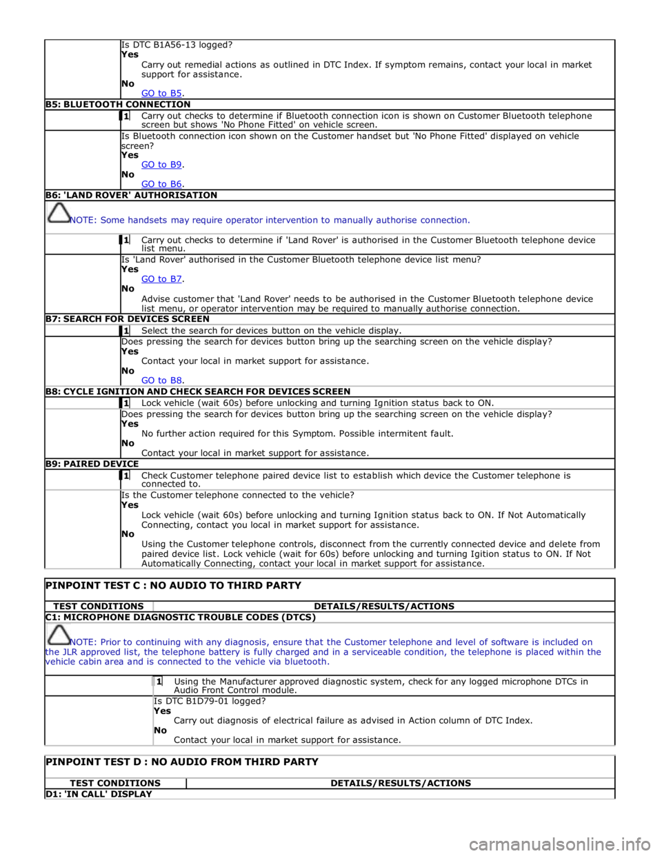
Is DTC B1A56-13 logged?
Yes
Carry out remedial actions as outlined in DTC Index. If symptom remains, contact your local in market
support for assistance.
No
GO to B5. B5: BLUETOOTH CONNECTION 1 Carry out checks to determine if Bluetooth connection icon is shown on Customer Bluetooth telephone screen but shows 'No Phone Fitted' on vehicle screen. Is Bluetooth connection icon shown on the Customer handset but 'No Phone Fitted' displayed on vehicle
screen?
Yes
GO to B9. No
GO to B6. B6: 'LAND ROVER' AUTHORISATION
NOTE: Some handsets may require operator intervention to manually authorise connection. 1 Carry out checks to determine if 'Land Rover' is authorised in the Customer Bluetooth telephone device list menu. Is 'Land Rover' authorised in the Customer Bluetooth telephone device list menu?
Yes
GO to B7. No
Advise customer that 'Land Rover' needs to be authorised in the Customer Bluetooth telephone device
list menu, or operator intervention may be required to manually authorise connection. B7: SEARCH FOR DEVICES SCREEN 1 Select the search for devices button on the vehicle display. Does pressing the search for devices button bring up the searching screen on the vehicle display?
Yes
Contact your local in market support for assistance.
No
GO to B8. B8: CYCLE IGNITION AND CHECK SEARCH FOR DEVICES SCREEN 1 Lock vehicle (wait 60s) before unlocking and turning Ignition status back to ON. Does pressing the search for devices button bring up the searching screen on the vehicle display?
Yes
No further action required for this Symptom. Possible intermitent fault.
No
Contact your local in market support for assistance. B9: PAIRED DEVICE 1 Check Customer telephone paired device list to establish which device the Customer telephone is connected to. Is the Customer telephone connected to the vehicle?
Yes
Lock vehicle (wait 60s) before unlocking and turning Ignition status back to ON. If Not Automatically
Connecting, contact you local in market support for assistance.
No
Using the Customer telephone controls, disconnect from the currently connected device and delete from
paired device list. Lock vehicle (wait for 60s) before unlocking and turning Igition status to ON. If Not Automatically Connecting, contact your local in market support for assistance.
PINPOINT TEST C : NO AUDIO TO THIRD PARTY TEST CONDITIONS DETAILS/RESULTS/ACTIONS C1: MICROPHONE DIAGNOSTIC TROUBLE CODES (DTCS)
NOTE: Prior to continuing with any diagnosis, ensure that the Customer telephone and level of software is included on
the JLR approved list, the telephone battery is fully charged and in a serviceable condition, the telephone is placed within the
vehicle cabin area and is connected to the vehicle via bluetooth. 1 Using the Manufacturer approved diagnostic system, check for any logged microphone DTCs in Audio Front Control module. Is DTC B1D79-01 logged? Yes
Carry out diagnosis of electrical failure as advised in Action column of DTC Index.
No
Contact your local in market support for assistance.
PINPOINT TEST D : NO AUDIO FROM THIRD PARTY TEST CONDITIONS DETAILS/RESULTS/ACTIONS D1: 'IN CALL' DISPLAY
Page 1940 of 3039
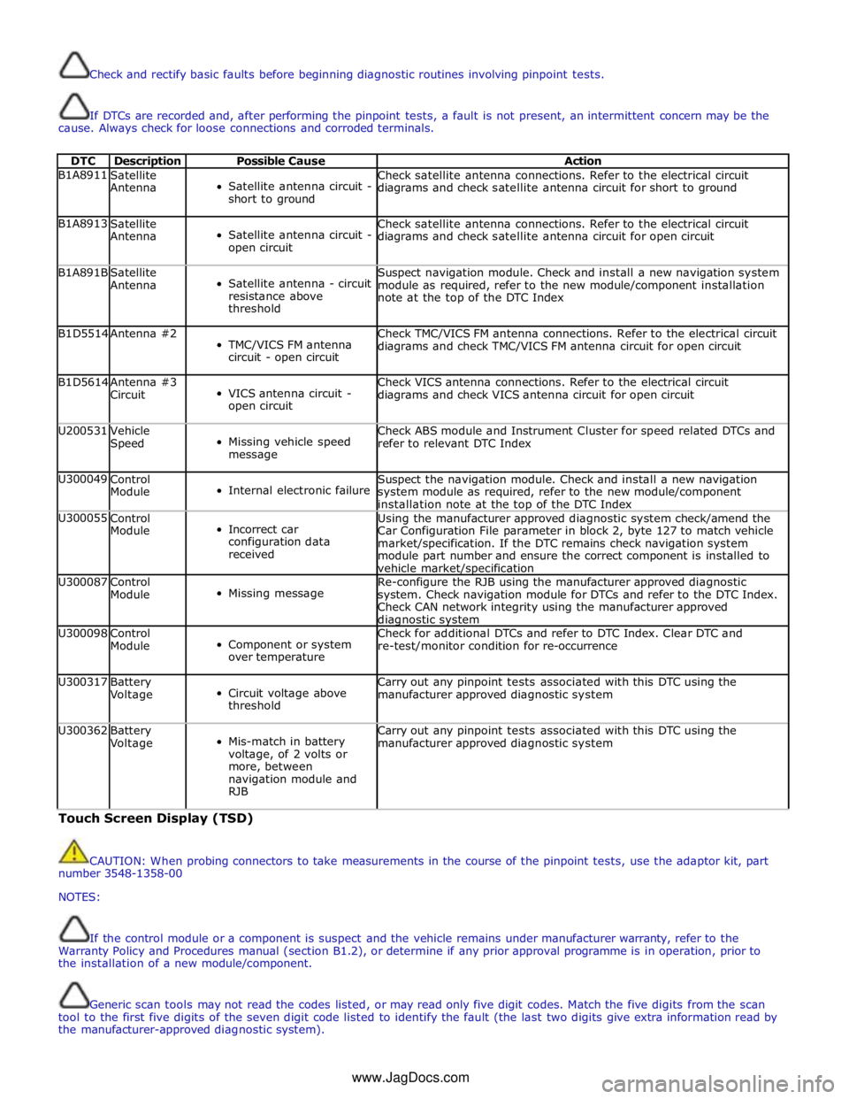
Check and rectify basic faults before beginning diagnostic routines involving pinpoint tests.
If DTCs are recorded and, after performing the pinpoint tests, a fault is not present, an intermittent concern may be the
cause. Always check for loose connections and corroded terminals.
DTC Description Possible Cause Action B1A8911
Satellite
Antenna
Satellite antenna circuit -
short to ground Check satellite antenna connections. Refer to the electrical circuit
diagrams and check satellite antenna circuit for short to ground B1A8913
Satellite
Antenna
Satellite antenna circuit -
open circuit Check satellite antenna connections. Refer to the electrical circuit
diagrams and check satellite antenna circuit for open circuit B1A891B
Satellite
Antenna
Satellite antenna - circuit
resistance above
threshold Suspect navigation module. Check and install a new navigation system
module as required, refer to the new module/component installation
note at the top of the DTC Index B1D5514 Antenna #2
TMC/VICS FM antenna
circuit - open circuit Check TMC/VICS FM antenna connections. Refer to the electrical circuit
diagrams and check TMC/VICS FM antenna circuit for open circuit B1D5614
Antenna #3
Circuit
VICS antenna circuit -
open circuit Check VICS antenna connections. Refer to the electrical circuit
diagrams and check VICS antenna circuit for open circuit U200531
Vehicle
Speed
Missing vehicle speed
message Check ABS module and Instrument Cluster for speed related DTCs and
refer to relevant DTC Index U300049
Control
Module
Internal electronic failure Suspect the navigation module. Check and install a new navigation
system module as required, refer to the new module/component
installation note at the top of the DTC Index U300055
Control
Module
Incorrect car
configuration data
received Using the manufacturer approved diagnostic system check/amend the
Car Configuration File parameter in block 2, byte 127 to match vehicle
market/specification. If the DTC remains check navigation system
module part number and ensure the correct component is installed to
vehicle market/specification U300087
Control
Module
Missing message Re-configure the RJB using the manufacturer approved diagnostic
system. Check navigation module for DTCs and refer to the DTC Index.
Check CAN network integrity using the manufacturer approved diagnostic system U300098
Control
Module
Component or system
over temperature Check for additional DTCs and refer to DTC Index. Clear DTC and
re-test/monitor condition for re-occurrence U300317
Battery
Voltage
Circuit voltage above
threshold Carry out any pinpoint tests associated with this DTC using the
manufacturer approved diagnostic system U300362
Battery
Voltage
Mis-match in battery
voltage, of 2 volts or
more, between
navigation module and
RJB Carry out any pinpoint tests associated with this DTC using the
manufacturer approved diagnostic system Touch Screen Display (TSD)
CAUTION: When probing connectors to take measurements in the course of the pinpoint tests, use the adaptor kit, part
number 3548-1358-00
NOTES:
If the control module or a component is suspect and the vehicle remains under manufacturer warranty, refer to the
Warranty Policy and Procedures manual (section B1.2), or determine if any prior approval programme is in operation, prior to
the installation of a new module/component.
Generic scan tools may not read the codes listed, or may read only five digit codes. Match the five digits from the scan
tool to the first five digits of the seven digit code listed to identify the fault (the last two digits give extra information read by
the manufacturer-approved diagnostic system).
www.JagDocs.com