diagnostic menu JAGUAR XFR 2010 1.G Owner's Manual
[x] Cancel search | Manufacturer: JAGUAR, Model Year: 2010, Model line: XFR, Model: JAGUAR XFR 2010 1.GPages: 3039, PDF Size: 58.49 MB
Page 2013 of 3039

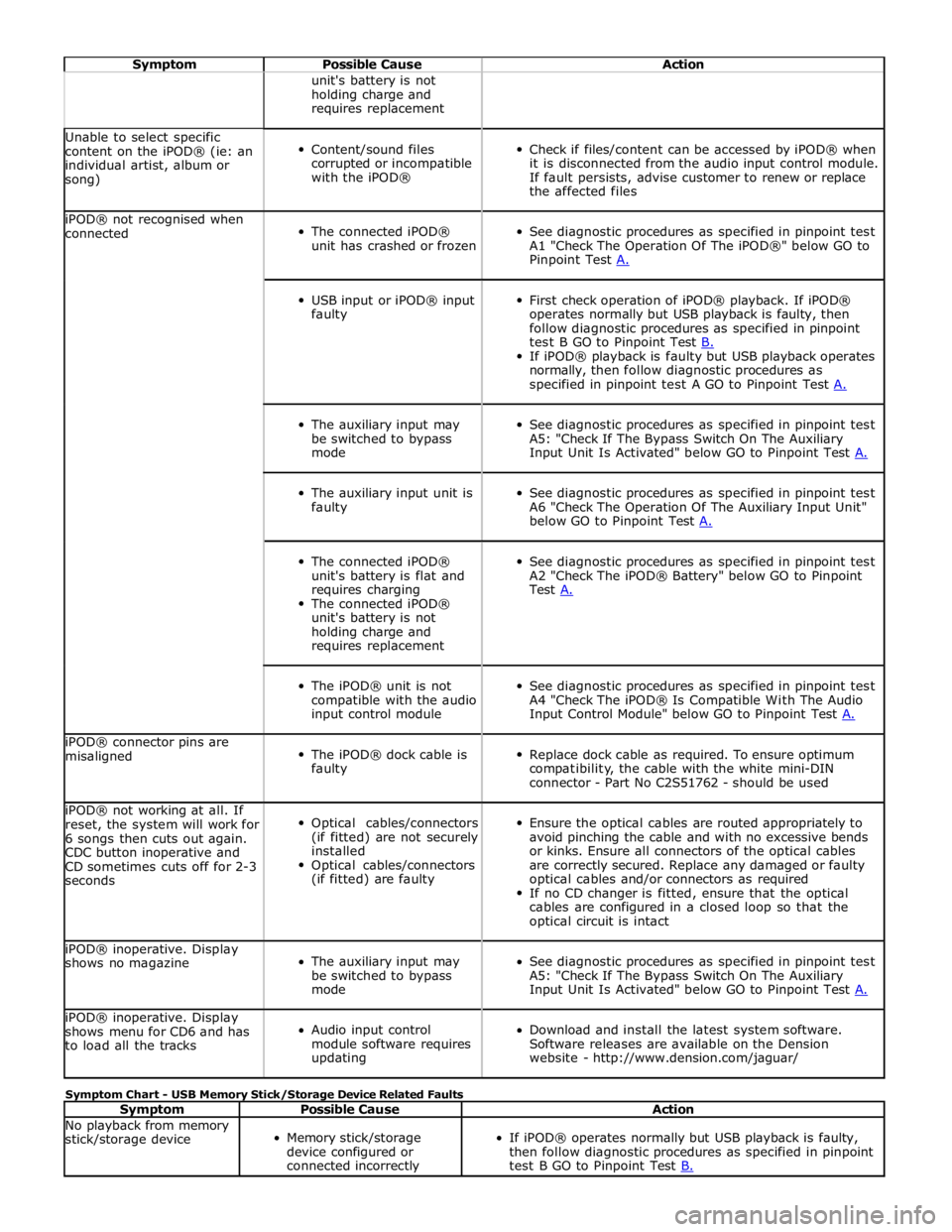
Symptom Possible Cause Action unit's battery is not
holding charge and
requires replacement Unable to select specific
content on the iPOD® (ie: an
individual artist, album or
song)
Content/sound files
corrupted or incompatible
with the iPOD®
Check if files/content can be accessed by iPOD® when
it is disconnected from the audio input control module.
If fault persists, advise customer to renew or replace
the affected files iPOD® not recognised when
connected
The connected iPOD®
unit has crashed or frozen
See diagnostic procedures as specified in pinpoint test
A1 "Check The Operation Of The iPOD®" below GO to
Pinpoint Test A.
USB input or iPOD® input
faulty
First check operation of iPOD® playback. If iPOD®
operates normally but USB playback is faulty, then
follow diagnostic procedures as specified in pinpoint
test B GO to Pinpoint Test B. If iPOD® playback is faulty but USB playback operates
normally, then follow diagnostic procedures as
specified in pinpoint test A GO to Pinpoint Test A.
The auxiliary input may
be switched to bypass
mode
See diagnostic procedures as specified in pinpoint test
A5: "Check If The Bypass Switch On The Auxiliary
Input Unit Is Activated" below GO to Pinpoint Test A.
The auxiliary input unit is
faulty
See diagnostic procedures as specified in pinpoint test
A6 "Check The Operation Of The Auxiliary Input Unit"
below GO to Pinpoint Test A.
The connected iPOD®
unit's battery is flat and
requires charging
The connected iPOD®
unit's battery is not
holding charge and
requires replacement
See diagnostic procedures as specified in pinpoint test
A2 "Check The iPOD® Battery" below GO to Pinpoint
Test A.
The iPOD® unit is not
compatible with the audio
input control module
See diagnostic procedures as specified in pinpoint test
A4 "Check The iPOD® Is Compatible With The Audio
Input Control Module" below GO to Pinpoint Test A. iPOD® connector pins are
misaligned
The iPOD® dock cable is
faulty
Replace dock cable as required. To ensure optimum
compatibility, the cable with the white mini-DIN
connector - Part No C2S51762 - should be used iPOD® not working at all. If
reset, the system will work for
6 songs then cuts out again.
CDC button inoperative and
CD sometimes cuts off for 2-3
seconds
Optical cables/connectors
(if fitted) are not securely
installed
Optical cables/connectors
(if fitted) are faulty
Ensure the optical cables are routed appropriately to
avoid pinching the cable and with no excessive bends
or kinks. Ensure all connectors of the optical cables
are correctly secured. Replace any damaged or faulty
optical cables and/or connectors as required
If no CD changer is fitted, ensure that the optical
cables are configured in a closed loop so that the
optical circuit is intact iPOD® inoperative. Display
shows no magazine
The auxiliary input may
be switched to bypass
mode
See diagnostic procedures as specified in pinpoint test
A5: "Check If The Bypass Switch On The Auxiliary
Input Unit Is Activated" below GO to Pinpoint Test A. iPOD® inoperative. Display
shows menu for CD6 and has
to load all the tracks
Audio input control
module software requires
updating
Download and install the latest system software.
Software releases are available on the Dension
website - http://www.dension.com/jaguar/ Symptom Chart - USB Memory Stick/Storage Device Related Faults
Symptom Possible Cause Action No playback from memory
stick/storage device
Memory stick/storage
device configured or
connected incorrectly
If iPOD® operates normally but USB playback is faulty,
then follow diagnostic procedures as specified in pinpoint
test B GO to Pinpoint Test B.
Page 2150 of 3039

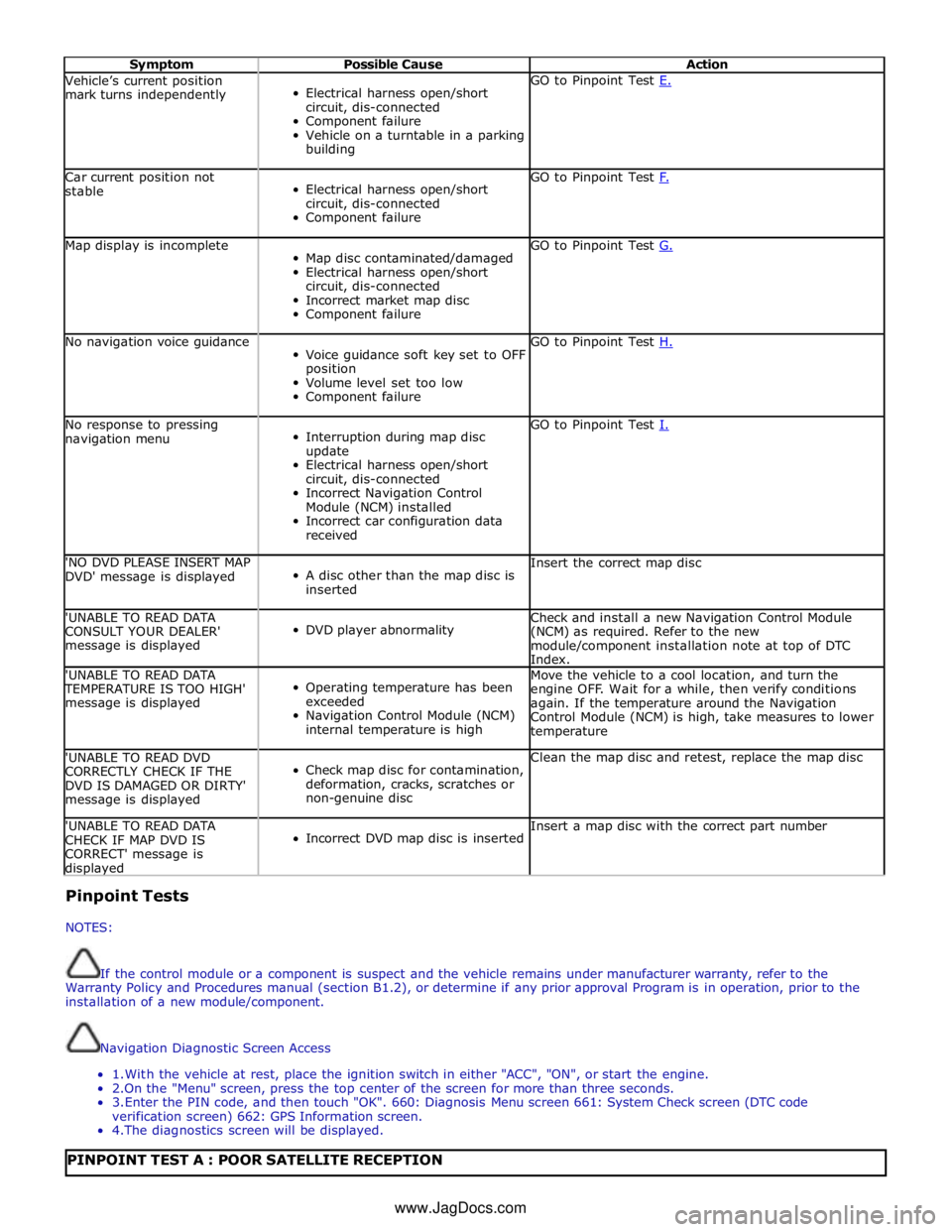
Symptom Possible Cause Action Vehicle’s current position
mark turns independently
Electrical harness open/short
circuit, dis-connected
Component failure
Vehicle on a turntable in a parking
building GO to Pinpoint Test E. Car current position not
stable
Electrical harness open/short
circuit, dis-connected
Component failure GO to Pinpoint Test F. Map display is incomplete
Map disc contaminated/damaged
Electrical harness open/short
circuit, dis-connected
Incorrect market map disc
Component failure GO to Pinpoint Test G. No navigation voice guidance
Voice guidance soft key set to OFF
position
Volume level set too low
Component failure GO to Pinpoint Test H. No response to pressing
navigation menu
Interruption during map disc
update
Electrical harness open/short
circuit, dis-connected
Incorrect Navigation Control
Module (NCM) installed
Incorrect car configuration data
received GO to Pinpoint Test I. 'NO DVD PLEASE INSERT MAP
DVD' message is displayed
A disc other than the map disc is
inserted Insert the correct map disc 'UNABLE TO READ DATA
CONSULT YOUR DEALER'
message is displayed
DVD player abnormality Check and install a new Navigation Control Module
(NCM) as required. Refer to the new
module/component installation note at top of DTC
Index. 'UNABLE TO READ DATA TEMPERATURE IS TOO HIGH'
message is displayed
Operating temperature has been
exceeded
Navigation Control Module (NCM)
internal temperature is high Move the vehicle to a cool location, and turn the
engine OFF. Wait for a while, then verify conditions
again. If the temperature around the Navigation
Control Module (NCM) is high, take measures to lower
temperature 'UNABLE TO READ DVD
CORRECTLY CHECK IF THE
DVD IS DAMAGED OR DIRTY'
message is displayed
Check map disc for contamination,
deformation, cracks, scratches or
non-genuine disc Clean the map disc and retest, replace the map disc 'UNABLE TO READ DATA
CHECK IF MAP DVD IS
CORRECT' message is displayed
Incorrect DVD map disc is inserted Insert a map disc with the correct part number Pinpoint Tests
NOTES:
If the control module or a component is suspect and the vehicle remains under manufacturer warranty, refer to the
Warranty Policy and Procedures manual (section B1.2), or determine if any prior approval Program is in operation, prior to the
installation of a new module/component.
Navigation Diagnostic Screen Access
1. With the vehicle at rest, place the ignition switch in either "ACC", "ON", or start the engine.
2.On the "Menu" screen, press the top center of the screen for more than three seconds.
3. Enter the PIN code, and then touch "OK". 660: Diagnosis Menu screen 661: System Check screen (DTC code
verification screen) 662: GPS Information screen.
4. The diagnostics screen will be displayed.
PINPOINT TEST A : POOR SATELLITE RECEPTION www.JagDocs.com
Page 2152 of 3039

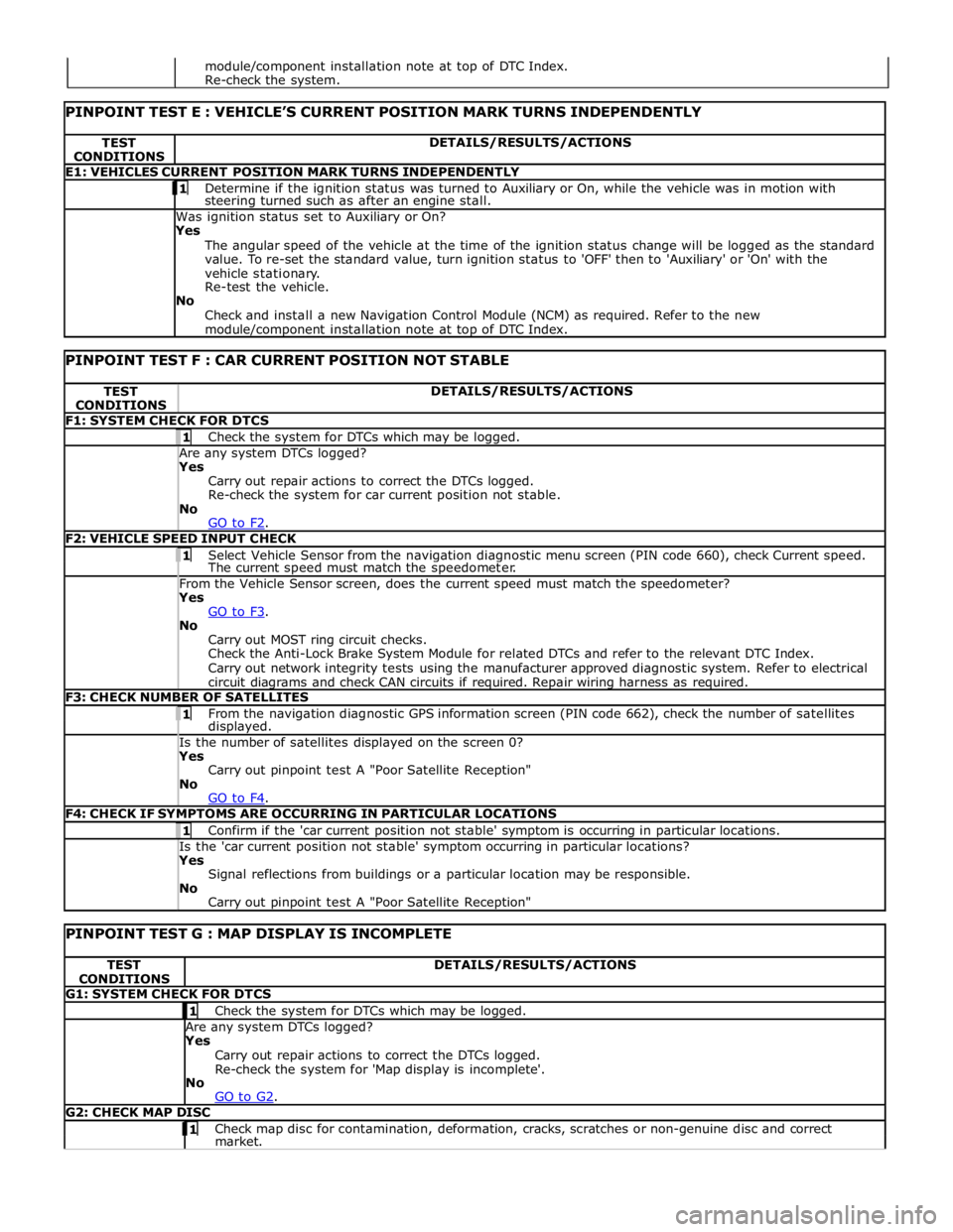
TEST
CONDITIONS DETAILS/RESULTS/ACTIONS E1: VEHICLES CURRENT POSITION MARK TURNS INDEPENDENTLY 1 Determine if the ignition status was turned to Auxiliary or On, while the vehicle was in motion with steering turned such as after an engine stall. Was ignition status set to Auxiliary or On?
Yes
The angular speed of the vehicle at the time of the ignition status change will be logged as the standard
value. To re-set the standard value, turn ignition status to 'OFF' then to 'Auxiliary' or 'On' with the
vehicle stationary.
Re-test the vehicle.
No
Check and install a new Navigation Control Module (NCM) as required. Refer to the new module/component installation note at top of DTC Index.
PINPOINT TEST F : CAR CURRENT POSITION NOT STABLE TEST
CONDITIONS DETAILS/RESULTS/ACTIONS F1: SYSTEM CHECK FOR DTCS 1 Check the system for DTCs which may be logged. Are any system DTCs logged? Yes
Carry out repair actions to correct the DTCs logged.
Re-check the system for car current position not stable.
No
GO to F2. F2: VEHICLE SPEED INPUT CHECK 1 Select Vehicle Sensor from the navigation diagnostic menu screen (PIN code 660), check Current speed. The current speed must match the speedometer. From the Vehicle Sensor screen, does the current speed must match the speedometer? Yes
GO to F3. No
Carry out MOST ring circuit checks.
Check the Anti-Lock Brake System Module for related DTCs and refer to the relevant DTC Index.
Carry out network integrity tests using the manufacturer approved diagnostic system. Refer to electrical
circuit diagrams and check CAN circuits if required. Repair wiring harness as required. F3: CHECK NUMBER OF SATELLITES 1 From the navigation diagnostic GPS information screen (PIN code 662), check the number of satellites displayed. Is the number of satellites displayed on the screen 0? Yes
Carry out pinpoint test A "Poor Satellite Reception"
No
GO to F4. F4: CHECK IF SYMPTOMS ARE OCCURRING IN PARTICULAR LOCATIONS 1 Confirm if the 'car current position not stable' symptom is occurring in particular locations. Is the 'car current position not stable' symptom occurring in particular locations? Yes
Signal reflections from buildings or a particular location may be responsible.
No
Carry out pinpoint test A "Poor Satellite Reception"
PINPOINT TEST G : MAP DISPLAY IS INCOMPLETE TEST
CONDITIONS DETAILS/RESULTS/ACTIONS G1: SYSTEM CHECK FOR DTCS 1 Check the system for DTCs which may be logged. Are any system DTCs logged? Yes
Carry out repair actions to correct the DTCs logged.
Re-check the system for 'Map display is incomplete'.
No
GO to G2. G2: CHECK MAP DISC 1 Check map disc for contamination, deformation, cracks, scratches or non-genuine disc and correct market. module/component installation note at top of DTC Index.
Re-check the system.
Page 2154 of 3039

Check the "Loading" button on the navigation diagnostics screen (PIN code 660) has been pressed, and "YES" has been selected. Has the "Loading" button on the navigation diagnostics screen been pressed, and has "YES" been selected? Yes
Check the correct map disc is inserted into the Navigation Control Module (NCM). Start the engine and
allow to idle for 15 minutesTurn the engine 'OFF', and then start the engine again.
No
Refer to electrical circuit diagrams and check integrity of navigation system wiring harness and
connectors.
GO to I4. I4: SYSTEM CHECK FOR DTCS 1 Check the system for DTCs which may be logged. Is DTC U300055 logged? Yes
Using the manufacturer approved diagnostic system check/amend the Car Configuration File parameter in
block 2, byte 127 to match vehicle market/specification. If the DTC remains check navigation system
module part number and ensure the correct component is installed to vehicle market/specification.
No
GO to I5. I5: NO RESPONSE TO PRESSING NAVIGATION MENU 1 Turn the engine 'OFF', wait for a moment, and then turn the engine 'ON' again. Does the navigation screen fail to display even if the navigation button is pressed? Yes
Check the HLDF is installed correctly.
Check the Navigation Control Module (NCM) is installed correctly.
No
Operation is normal. DTC Index
For a list of Diagnostic Trouble Codes (DTCs) that could be logged on this vehicle, please refer to Section 100-00.
REFER to: Diagnostic Trouble Code (DTC) Index - DTC: Navigation Control Module (NCM) (100-00, Description and Operation).