display JAGUAR XFR 2010 1.G Owner's Manual
[x] Cancel search | Manufacturer: JAGUAR, Model Year: 2010, Model line: XFR, Model: JAGUAR XFR 2010 1.GPages: 3039, PDF Size: 58.49 MB
Page 610 of 3039
BRAKE CALIPERS System Operation
When hydraulic pressure is supplied to the caliper, the pistons extend to force the inner pad against the brake disc. The caliper
reacts and slides along two guide pins to bring the outer pad into contact with the brake disc.
BRAKE PAD WEAR SENSORS
When a brake pad incorporating a brake pad wear sensor is approximately 75% worn, the sensor wire within the pad material
is worn through and the brake pad wear sensor goes open circuit. When the instrument cluster detects the open circuit, it
illuminates the amber LED (light emitting diode) in the brake warning indicator, displays an appropriate warning in the
message center and sounds a warning chime.
Refer to: Instrument Cluster (413-01 Instrument Cluster, Description and Operation).
NOTE: A new pad wear sensor lead must be fitted whenever the brake pads are changed, irrespective of the brake pad
warning sensor being triggered.
BRAKE CALIPERS Component Description
Each caliper is mounted within a fixed carrier that is secured to the front wheel knuckle with two bolts. The inboard brake pad
of the LH (left-hand) brake incorporates a wear sensor.
Each outboard brake pad is installed with a pressed steel anti-rattle spring. On SC (supercharger) vehicles, a badge with the
'R' symbol is formed on the anti-rattle spring.
BRAKE PAD WEAR SENSORS
The brake pad wear sensor is wired in series with a wear sensor on the RH (right-hand) rear brake and the instrument cluster.
If the thickness of one of the brake pads connected to a wear sensor decreases to a predetermined limit, the instrument
cluster illuminates the brake warning indicator.
Page 632 of 3039
BRAKE CALIPERS System Operation
When hydraulic pressure is supplied to the caliper, the pistons extend to force the inner pad against the brake disc. The caliper
reacts and slides along two guide pins to bring the outer pad into contact with the brake disc.
BRAKE PAD WEAR SENSORS
When a brake pad incorporating a brake pad wear sensor is approximately 75% worn, the sensor wire within the pad material
is worn through and the brake pad wear sensor goes open circuit. When the instrument cluster detects the open circuit, it
illuminates the amber LED (light emitting diode) in the brake warning indicator, displays an appropriate warning in the
message center and sounds a warning chime.
Refer to: Instrument Cluster (413-01 Instrument Cluster, Description and Operation).
NOTE: A new pad wear sensor lead must be fitted whenever the brake pads are changed, irrespective of the brake pad
warning sensor being triggered.
BRAKE CALIPERS Component Description
Each caliper is mounted within a fixed carrier that is secured to the rear wheel knuckle with two bolts. Each outboard brake pad
is installed with a wire anti-rattle spring.
The brake calipers on SC (supercharger) vehicles are painted and also include a logo badge, secured with two screws, which
must be removed in order to change the brake pads.
The inboard brake pad of the RH (right-hand) brake incorporates a wear sensor.
BRAKE PAD WEAR SENSORS
The brake pad wear sensor is wired in series with a wear sensor on the LH (left-hand) front brake and the instrument cluster. If
the thickness of one of the brake pads connected to a wear sensor decreases to a predetermined limit, the instrument cluster
illuminates the brake warning indicator.
Page 648 of 3039

7 Instrument cluster 8 Parking brake switch 9 Parking brake actuator
Static Apply System Operation
The EPB module receives a vehicle speed signal from the ABS (anti-lock brake system) module on the high speed CAN bus. If the parking brake switch is pulled to the 'Apply' position and vehicle speed is less than 2 mph (3 km/h), the EPB module will
instigate its 'Static Apply' mode and drive the actuator to apply full parking brake force to the rear wheels.
The EPB module monitors the current drawn by the actuator and compares this to information held within its configuration
software to determine when full braking force has been applied.
Dynamic Apply
There are two 'Dynamic Apply' modes; low speed dynamic and high speed dynamic. The low speed dynamic mode operates at
speeds between 2 mph (3 km/h) and 20 mph (32 km/h). The high speed dynamic mode operates at speeds above 20 mph (32
km/h).
If the parking brake switch is pulled up to the 'Apply' position and vehicle speed is within the low speed dynamic range, the
EPB module drives the actuator to apply full parking brake force to the rear wheels.
If the parking brake switch is pulled up to the 'Apply' position and vehicle speed is within the high speed dynamic range, the
EPB module will apply braking force to the rear wheels at a slower rate until full braking load is reached or the switch is
released. The rate with which braking force is applied is controlled by the EPB module, which monitors both current drawn by
the actuator and positional information from the actuator hall sensor and compares this to information held within its
configuration software.
Drive Away Release
The EPB module will initiate its 'Drive Away Release' function and automatically release the parking brake if the following
conditions are detected:
The engine is running.
Drive , or reverse is selected.
Positive throttle movement is detected.
The EPB module receives messages of gear selector position and throttle angle over the high speed CAN bus from the TCM (transmission control module) and the ECM (engine control module) respectively.
Release from Park
The EPB module will initiate its 'Release from Park' function and automatically release the parking brake if the gear selector is
moved from Park to any position except Neutral.
Repairs
Before carrying out any work on the parking brake system, the Jaguar approved diagnostic system must be connected and the
'parking brake unjam' routine run. The routine can be found in the 'Vehicle Configuration' area, under the 'Set-up and
Configuration' menu. After any work has been carried out on the parking brake, the system will require resetting.
CAUTION: Do not use the 'Emergency Release' tool to allow work to be carried out on the parking brake. Work can only be
carried out on the parking brake system after the 'parking brake unjam' routine has been run.
Resetting
If the electrical supply is disconnected from the EPB module, the actuator will loose its position memory. On battery
re-connection and ignition on, 'APPLY FOOT AND PARK BRAKE' will be displayed in the instrument cluster message center
indicating the parking brake requires resetting.
Refer to: Parking Brake (206-05, Diagnosis and Testing).
Operating Voltages
The EPB module will only operate the actuator if the power supply from the battery is between 9 V and 16 V. At any voltage
within this range, the actuator is able to fully tighten and release the brake cables. If the power supply falls outside of the
range, a fault code is stored in the EPB module and can be retrieved using the Jaguar approved diagnostic system.
Page 654 of 3039

Symptom Possible Cause Action The parking brake will not
engage or release (with
parking brake warning
message)
Cables fouled, trapped or damaged
Cables incorrectly routed or installed
Rear lining wear
Actuator malfunction
Caliper malfunction
Check the rear and primary
cables for correct installation
and damage
Inspect the rear brake linings for
wear
Re-calibrate the parking brake,
refer to the calibration procedure
Check the rear service brake for
correct installation and operation No communication with the
parking brake module
Fuse
Module off Bus
CAN network error
Parking brake module fault
Check fuses
Ensure battery is fully charged
and in serviceable condition.
Check battery voltage at parking
brake module
Check CAN network using
manufacturer approved
diagnostic system 'Park brake Fault' displayed on
message center with
associated warning lamps
Parking brake system fault
Check the parking brake module
for DTCs and refer to DTC Index Brakes drag
Parking brake not re-calibrated after battery has
been disconnected or has been in a state of
discharge, or repairs have been carried out to
the rear service or parking brake system
Service brake system fault
Re-calibrate parking brake, refer
to the calibration procedure
Check the service brake for
correct operation DTC Index
For a list of diagnostic trouble codes that could be logged on this vehicle, please refer to Section 100-00.
REFER to: Diagnostic Trouble Code (DTC) Index - DTC: Electric Parking Brake (PBM) (100-00 General Information, Description and Operation).
Page 695 of 3039
Press and hold the DSC switch for less than 10 seconds.
The message center will temporarily display either Trac DSC or DSC ON.
The warning indicator in the instrument panel will illuminate while Trac DSC is selected.
The warning indicator will flash when DSC or Trac DSC is active.
NOTE: If cruise control is engaged, it will automatically disengage if DSC activates.
Refer to: Speed Control (310-03 Speed Control - 2.7L V6 - TdV6, Description and Operation).
Corner Brake Control
CBC (corner brake control) influences the brake pressures, below and within DSC and ABS thresholds, to counteract the yawing moment produced when braking in a corner. CBC produces a correction torque by limiting the brake pressure on one side of the
vehicle.
Electronic Brake Force Distribution
EBD (electronic brake force distribution) limits the brake pressure applied to the rear wheels. When the brakes are applied, the
weight of the vehicle transfers forwards, reducing the ability of the rear wheels to transfer braking effort to the road surface.
This may cause the rear wheels to slip and make the vehicle unstable.
EBD uses the ABS braking hardware to automatically optimize the pressure to the rear brakes, below the point where ABS is normally invoked.
NOTE: Only the rear brakes are controlled by the EBD function.
Electronic Traction Control
ETC (electronic traction control) attempts to optimize forward traction by reducing engine torque, or by applying the brake of a
spinning wheel until traction is regained.
ETC is activated if an individual wheel speed is above that of the vehicle reference speed (positive slip) and the brake pedal is
not pressed. The brake is applied to the spinning wheel, allowing the excess torque to be transmitted to the non-spinning
wheel through the drive line. If necessary, the ABS module also sends a high speed CAN bus message to the ECM to request a reduction in engine torque.
When the DSC function is selected off using the DSC switch, the braking and engine torque reduction features are both
disabled, except when the JaguarDrive control is in winter mode. When the JaguarDrive control is in winter mode, selecting the
DSC function off retains the braking and engine torque reduction features, but reduces intervention levels compared to DSC
and Trac DSC modes.
Emergency Brake Assist
EBA (emergency brake assist) assists the driver in emergency braking situations by automatically increasing the applied
braking effort. The ABS module invokes EBA when: The brake pedal is rapidly pressed.
The brake pedal is pressed hard enough to bring the front brakes into ABS operation.
When the brake pedal is rapidly pressed, the ABS module increases the hydraulic pressure to all of the brakes until the threshold for ABS operation is reached. This action applies the maximum braking effort for the available traction. The ABS module monitors for the sudden application of the brakes, using inputs from the brake pedal switch and from the pressure
sensor within the HCU (hydraulic control unit). With the brake pedal pressed, if the rate of increase of hydraulic pressure
exceeds the predetermined limit, the ABS module invokes emergency braking.
When the brake pedal is pressed hard enough to bring the front brakes into ABS operation, the ABS module increases the hydraulic pressure to the rear brakes up to the ABS threshold.
EBA operation continues until the driver releases the brake pedal, sufficiently for the hydraulic pressure in the HCU to drop below a threshold value stored in the ABS module.
Engine Drag-Torque Control
EDC (engine drag-torque control) prevents wheel slip caused by any of the following: A
sudden decrease in engine torque when the accelerator is suddenly released.
A downshift using the Jaguar sequential shift function on automatic transmission vehicles.
When the ABS module detects the onset of wheel slip without the brakes being applied, the ABS module signals the ECM via the high speed CAN bus to request a momentary increase in engine torque.
Understeer Control
Understeer Logic Control is a proactive system which monitors the vehicle for understeer by comparing signals from the yaw
rate and lateral acceleration sensor with signals from the steering angle sensor and wheel speed sensors. www.JagDocs.com
Page 697 of 3039
DSC becomes active whenever the engine is running. A momentary press of the switch allows the driver to toggle between the
standard DSC settings and the optimized 'Trac DSC' settings. The message 'Trac DSC' or 'DSC on' will temporarily be displayed
in the instrument cluster message center. The amber DSC warning indicator in the instrument cluster remains illuminated while
'Trac DSC' is selected.
The DSC can be switched off by pressing and holding the switch for more than 10 seconds.
In each case the message 'DSC OFF' will be displayed in the instrument cluster message center to confirm DSC has been
switched off. The amber DSC warning indicator in the instrument cluster will remain illuminated. The system can be switched
back on again by simply pressing and releasing the switch. The message 'DSC ON' will then temporarily appear in the
instrument cluster message center to confirm the system is on.
NOTE: Switch requests may be delayed if the switch is pressed while a DSC operation is taking place. The switch request
will be displayed in the instrument cluster but the ABS module will not initiate any stability changes until it is safe to do so.
If a fault is detected with the DSC switch, the ABS module defaults to the 'DSC ON' setting and any switch requests are ignored.
WARNING: It is recommended that when using snow chains, Trac DSC is switched off and JaguarDrive control winter mode
is selected.
Wheel Speed Sensors
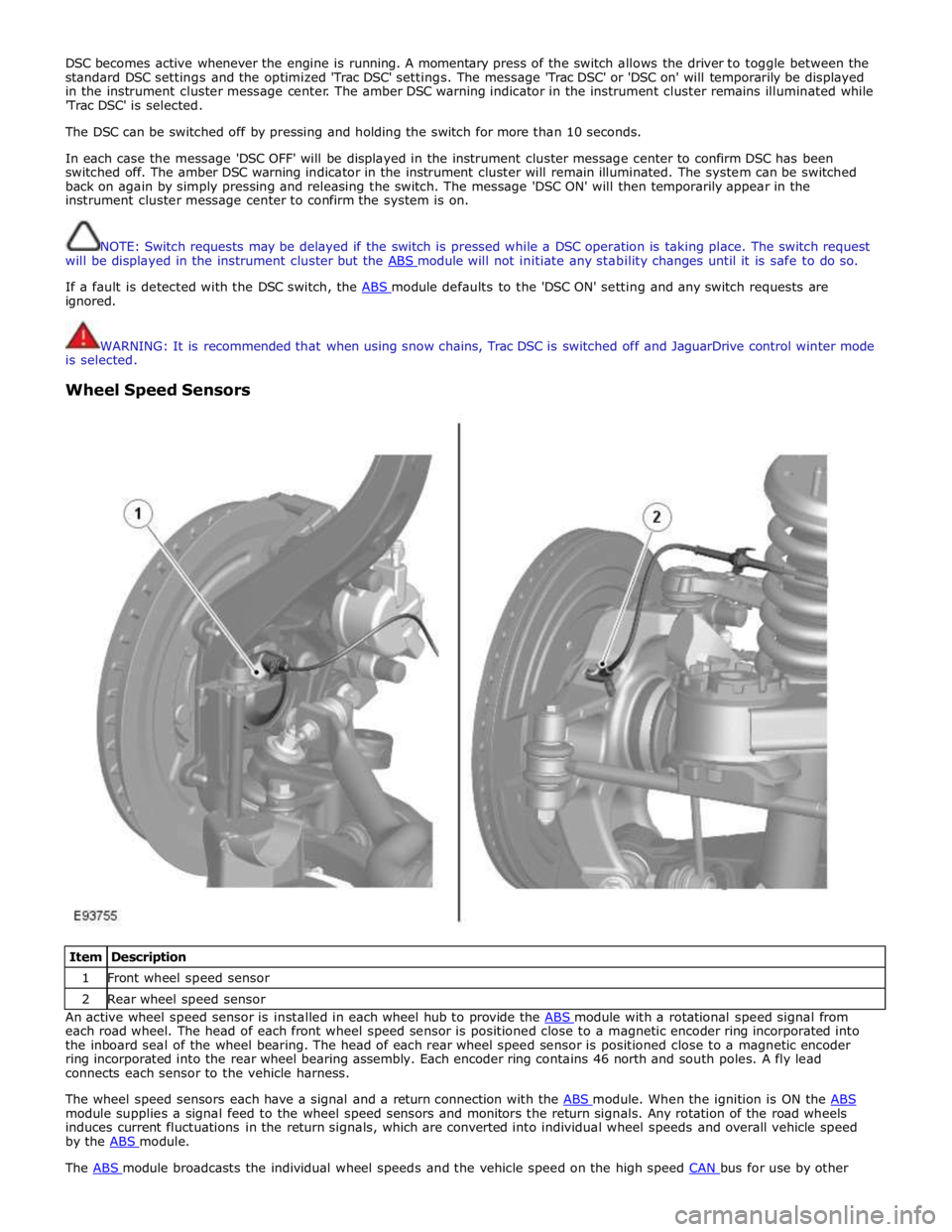
Item Description 1 Front wheel speed sensor 2 Rear wheel speed sensor An active wheel speed sensor is installed in each wheel hub to provide the ABS module with a rotational speed signal from each road wheel. The head of each front wheel speed sensor is positioned close to a magnetic encoder ring incorporated into
the inboard seal of the wheel bearing. The head of each rear wheel speed sensor is positioned close to a magnetic encoder
ring incorporated into the rear wheel bearing assembly. Each encoder ring contains 46 north and south poles. A fly lead
connects each sensor to the vehicle harness.
The wheel speed sensors each have a signal and a return connection with the ABS module. When the ignition is ON the ABS module supplies a signal feed to the wheel speed sensors and monitors the return signals. Any rotation of the road wheels
induces current fluctuations in the return signals, which are converted into individual wheel speeds and overall vehicle speed
by the ABS module. The ABS module broadcasts the individual wheel speeds and the vehicle speed on the high speed CAN bus for use by other
Page 699 of 3039
beams change state. The LEDs and detectors are mounted in such a way that only one beam will change state, either to broken or restored, at any one time.
The center (straight ahead) position of the steering wheel has to be learned by the ABS module every time the ignition is switched ON. The steering angle sensor is unable to determine the center position so inputs from the yaw rate and lateral
acceleration sensor and wheel speed signals are also used by the ABS module to help it perform this process. If extreme weather conditions are present, for example ice causing extreme wheel spin or understeer/oversteer, the ABS module may not be able to determine the center position of the steering wheel. In this situation 'DSC NOT AVAILABLE' will be displayed in the
instrument cluster message center and the amber warning indicator will illuminate.
Refer to: Information and Message Center (413-08 Information and Message Center, Description and Operation).
'DSC NOT AVAILABLE' will also be displayed if the ABS module detects a steering angle sensor fault. The amber warning indicator will illuminate until the fault is rectified.
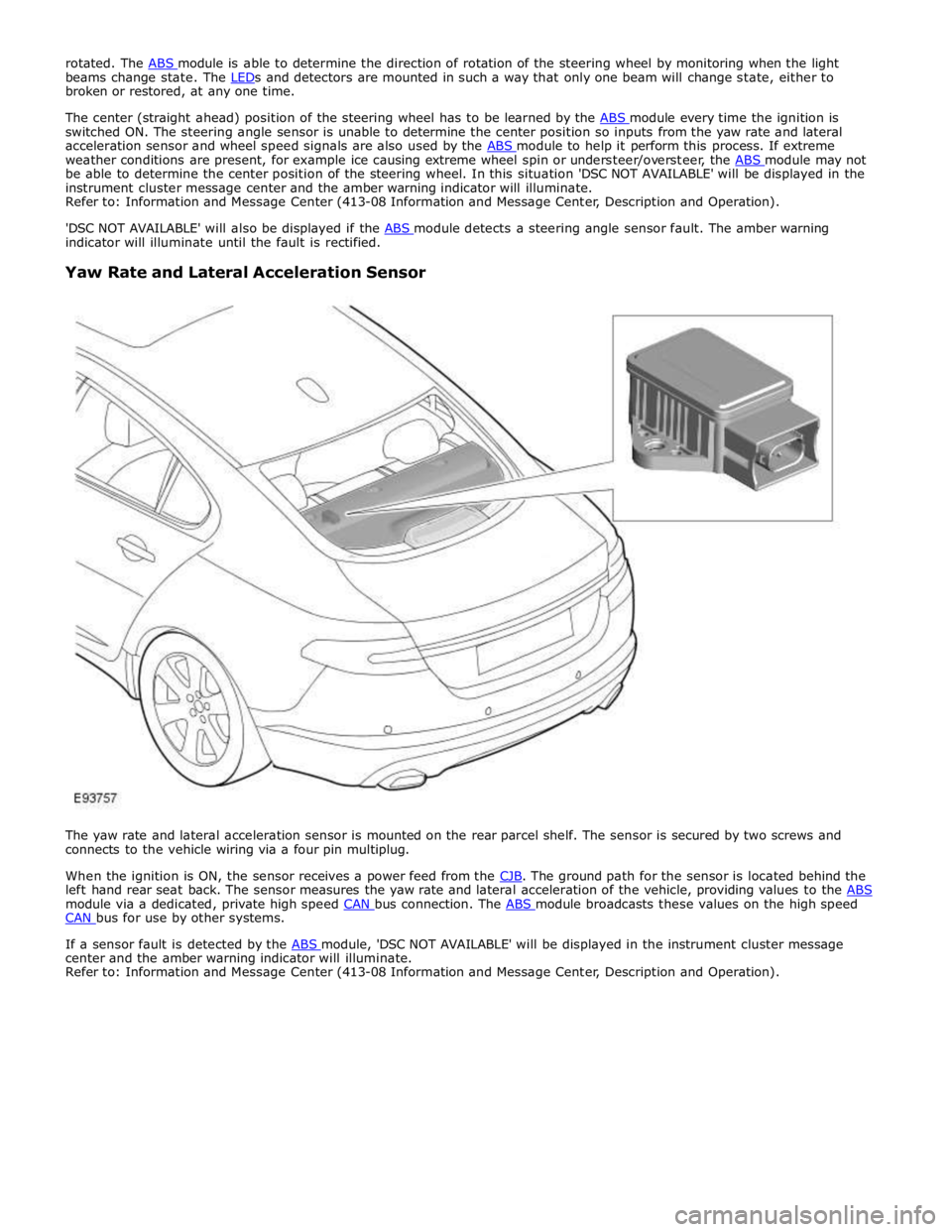
Yaw Rate and Lateral Acceleration Sensor
The yaw rate and lateral acceleration sensor is mounted on the rear parcel shelf. The sensor is secured by two screws and
connects to the vehicle wiring via a four pin multiplug.
When the ignition is ON, the sensor receives a power feed from the CJB. The ground path for the sensor is located behind the left hand rear seat back. The sensor measures the yaw rate and lateral acceleration of the vehicle, providing values to the ABS module via a dedicated, private high speed CAN bus connection. The ABS module broadcasts these values on the high speed CAN bus for use by other systems.
If a sensor fault is detected by the ABS module, 'DSC NOT AVAILABLE' will be displayed in the instrument cluster message center and the amber warning indicator will illuminate.
Refer to: Information and Message Center (413-08 Information and Message Center, Description and Operation).
Page 701 of 3039
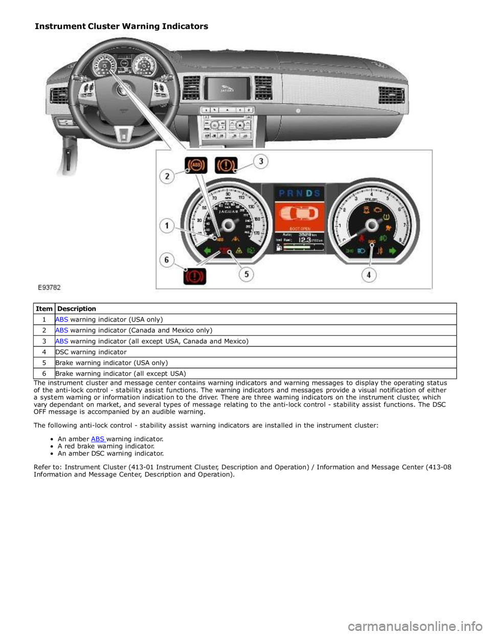
Item Description 1 ABS warning indicator (USA only) 2 ABS warning indicator (Canada and Mexico only) 3 ABS warning indicator (all except USA, Canada and Mexico) 4 DSC warning indicator 5 Brake warning indicator (USA only) 6 Brake warning indicator (all except USA) The instrument cluster and message center contains warning indicators and warning messages to display the operating status
of the anti-lock control - stability assist functions. The warning indicators and messages provide a visual notification of either
a system warning or information indication to the driver. There are three warning indicators on the instrument cluster, which
vary dependant on market, and several types of message relating to the anti-lock control - stability assist functions. The DSC
OFF message is accompanied by an audible warning.
The following anti-lock control - stability assist warning indicators are installed in the instrument cluster:
An amber ABS warning indicator. A red brake warning indicator.
An amber DSC warning indicator.
Refer to: Instrument Cluster (413-01 Instrument Cluster, Description and Operation) / Information and Message Center (413-08
Information and Message Center, Description and Operation). Instrument Cluster Warning Indicators
Page 702 of 3039
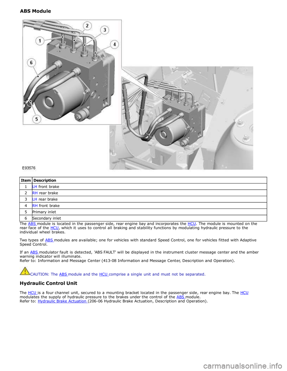
ABS Module
Item Description 1 LH front brake 2 RH rear brake 3 LH rear brake 4 RH front brake 5 Primary inlet 6 Secondary inlet The ABS module is located in the passenger side, rear engine bay and incorporates the HCU. The module is mounted on the rear face of the HCU, which it uses to control all braking and stability functions by modulating hydraulic pressure to the individual wheel brakes.
Two types of ABS modules are available; one for vehicles with standard Speed Control, one for vehicles fitted with Adaptive Speed Control.
If an ABS modulator fault is detected, 'ABS FAULT' will be displayed in the instrument cluster message center and the amber warning indicator will illuminate.
Refer to: Information and Message Center (413-08 Information and Message Center, Description and Operation).
CAUTION: The ABS module and the HCU comprise a single unit and must not be separated.
Hydraulic Control Unit
The HCU is a four channel unit, secured to a mounting bracket located in the passenger side, rear engine bay. The HCU modulates the supply of hydraulic pressure to the brakes under the control of the ABS module. Refer to: Hydraulic Brake Actuation (206-06 Hydraulic Brake Actuation, Description and Operation).
Page 797 of 3039

Published: 11-May-2011
Steering Column Switches - Steering Column Switches - Overview
Description and Operation
OVERVIEW
The steering column multifunction switch is situated on the steering column and consists of the wiper switch, the turn signal
indicator/lighting switch and the trip computer switch.
The RH (right-hand) multifunction switch controls the following windshield wiper functions:
Flick wipe
Intermittent wipe
Slow speed wipe
High speed wipe
Wash/Wipe
Headlamp powerwash
Rain sensing / variable wipe selection.
The LH (left-hand) multifunction switch controls the following functions:
Turn signal indicators
Side lamps
Headlamps
Auto lamps
High/low beam
Headlamp flash
Headlamp timer
Trip computer.
The steering column adjustment switch is located in the steering column lower shroud on the LH side. The switch is a 4 position 'joystick' which controls reach and rake adjustment.
The trip button allows the driver to cycle though an option menu and also reset trip cycle mileage calculations. The trip
computer information is displayed in the instrument cluster message centre.
Steering wheel mounted switches on the LH side of the driver's airbag, control the audio and telephone functions. Switches on the RH side of the driver's airbag, control the speed control functions. The steering wheel has an internal heating element. This is controlled by the driver via the Touch Screen Display (TSD). www.JagDocs.com