display JAGUAR XFR 2010 1.G Owner's Guide
[x] Cancel search | Manufacturer: JAGUAR, Model Year: 2010, Model line: XFR, Model: JAGUAR XFR 2010 1.GPages: 3039, PDF Size: 58.49 MB
Page 803 of 3039

automatically reset once the applicable remote handset has been detected by the vehicle security systems.
STEERING WHEEL HEATER
On certain models the rim of the steering wheel contains a heater element. Operation of the heater is selected using the
Touch Screen Display (TSD).
The heater temperature is controlled by a heated steering wheel control module located within the steering wheel. Power for
the heater element is supplied to the steering wheel via 2 contacts on the clockspring and a slip ring mounted on the steering
wheel.
Page 828 of 3039

5. NOTE: A flashing green light indicates low battery voltage.
In this case, place the battery on charge and make sure
that the battery is fully charged before using the smoke
test equipment.
Observe the power indicator lamp on the smoke test
equipment. Make sure that a continuous green light is
displayed.
6. NOTES:
In some cases it may be necessary to remove the air
cleaner(s) to allow access to the air cleaner outlet pipes.
In some cases it will be necessary to cap one of the
air cleaner outlet pipes. Use the blanking caps supplied in
the kit to cap the open orifice.
Disconnect the air cleaner outlet pipe(s).
Page 840 of 3039

4. NOTE: Dry cylinder compression test.
Install the compression test gauge.
5. NOTES:
This step requires the aid of another technician.
Print graphic number E164747 in step 11. Use this
graphic to record each cylinder compression figure.
The vehicle battery must be in good condition and fully
charged before carrying out this procedure.
Crank the engine for 10 seconds and record the figure
displayed on the compression test gauge. Make sure the
pressure is released from the compression test gauge after
each cylinder recording. Repeat the process for all cylinders.
Page 842 of 3039
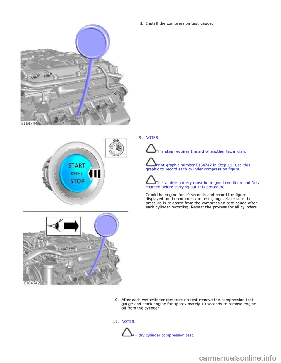
8. Install the compression test gauge.
9. NOTES:
This step requires the aid of another technician.
Print graphic number E164747 in Step 11. Use this
graphic to record each cylinder compression figure.
The vehicle battery must be in good condition and fully
charged before carrying out this procedure.
Crank the engine for 10 seconds and record the figure
displayed on the compression test gauge. Make sure the
pressure is released from the compression test gauge after
each cylinder recording. Repeat the process for all cylinders.
10.
After each wet cylinder compression test remove the compression test
gauge and crank engine for approximately 10 seconds to remove engine
oil from the cylinder
11. NOTES:
A= dry cylinder compression test.
Page 868 of 3039
cooling jets and the timing chain lubrication jets.
The oil returns to the oil pan under gravity. Large drain holes through the cylinder heads and cylinder block ensure the rapid
return of the oil to the sump pan. System replenishment is through the oil filler cap on the LH cylinder head cover.
An oil evacuation tube is installed to allow oil to be drawn from the sump pan. The upper end of the oil evacuation tube is
located under the oil filler cap.
An oil drain plug is installed in the RH side of the sump pan.
Oil Pump Nominal Operating Pressures
Engine Speed, rev/min Temperature, °C (°F) Pressure, bar (lbf/in2
) Idle 20 (68) 2.0 (29.0) 1500 20 (68) 6.0 (87.0) 3000 40 (104) 6.2 (90.0) 3000 110 (230) 5.0 (72.5) 3000 130 (266) 4.0 (58.0) Oil Level Monitoring
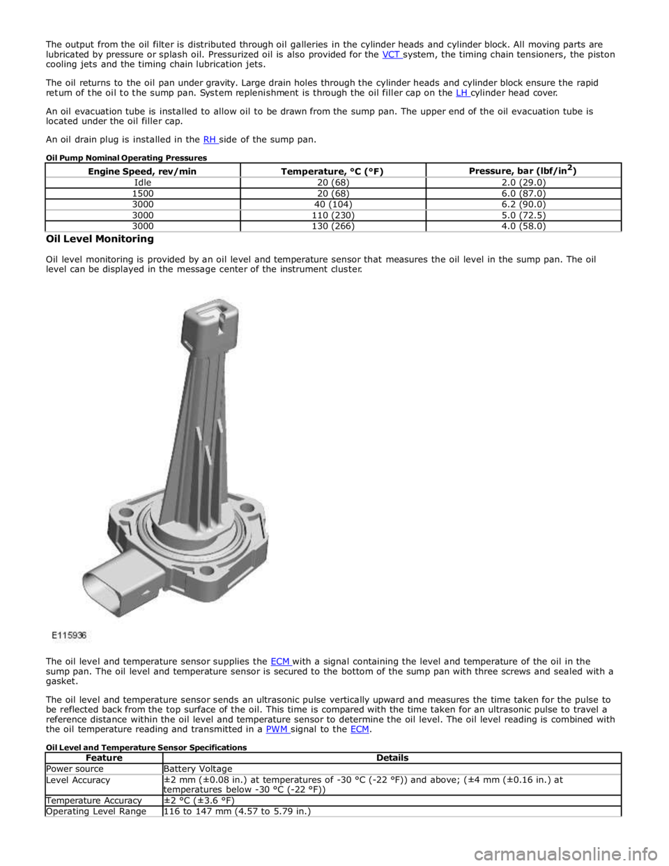
Oil level monitoring is provided by an oil level and temperature sensor that measures the oil level in the sump pan. The oil
level can be displayed in the message center of the instrument cluster.
The oil level and temperature sensor supplies the ECM with a signal containing the level and temperature of the oil in the sump pan. The oil level and temperature sensor is secured to the bottom of the sump pan with three screws and sealed with a
gasket.
The oil level and temperature sensor sends an ultrasonic pulse vertically upward and measures the time taken for the pulse to
be reflected back from the top surface of the oil. This time is compared with the time taken for an ultrasonic pulse to travel a
reference distance within the oil level and temperature sensor to determine the oil level. The oil level reading is combined with
the oil temperature reading and transmitted in a PWM signal to the ECM.
Oil Level and Temperature Sensor Specifications
Feature Details Power source Battery Voltage Level Accuracy ±2 mm (±0.08 in.) at temperatures of -30 °C (-22 °F)) and above; (±4 mm (±0.16 in.) at
temperatures below -30 °C (-22 °F)) Temperature Accuracy ±2 °C (±3.6 °F) Operating Level Range 116 to 147 mm (4.57 to 5.79 in.)
Page 869 of 3039
Operating Temperature Range -40 to 160 °C (-40 to 320 °F) Oil Level Check
For additional information, refer to Engine Oil Draining and Filling (303-01A, General Procedures).
For accuracy, oil level checks should be performed with the vehicle on level ground when the oil is hot. The vehicle needs to
stand for approximately 10 minutes, after the engine is switched off, to allow the oil to drain back into the sump pan and the
oil level to stabilize. The oil level system will not give a reading until the oil level has stabilized.
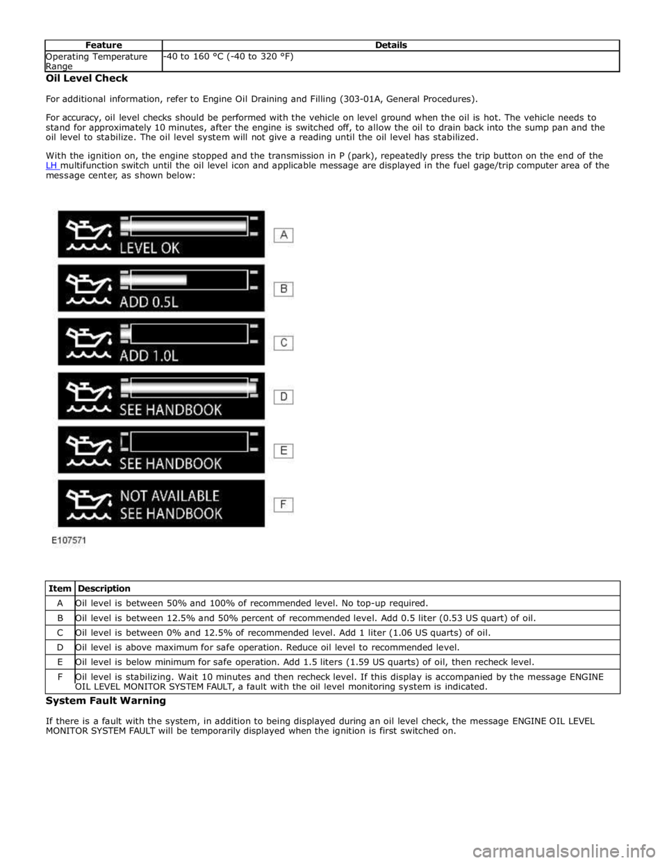
With the ignition on, the engine stopped and the transmission in P (park), repeatedly press the trip button on the end of the
LH multifunction switch until the oil level icon and applicable message are displayed in the fuel gage/trip computer area of the message center, as shown below:
Item Description A Oil level is between 50% and 100% of recommended level. No top-up required. B Oil level is between 12.5% and 50% percent of recommended level. Add 0.5 liter (0.53 US quart) of oil. C Oil level is between 0% and 12.5% of recommended level. Add 1 liter (1.06 US quarts) of oil. D Oil level is above maximum for safe operation. Reduce oil level to recommended level. E Oil level is below minimum for safe operation. Add 1.5 liters (1.59 US quarts) of oil, then recheck level. F Oil level is stabilizing. Wait 10 minutes and then recheck level. If this display is accompanied by the message ENGINE OIL LEVEL MONITOR SYSTEM FAULT, a fault with the oil level monitoring system is indicated. System Fault Warning
If there is a fault with the system, in addition to being displayed during an oil level check, the message ENGINE OIL LEVEL
MONITOR SYSTEM FAULT will be temporarily displayed when the ignition is first switched on.
Page 876 of 3039
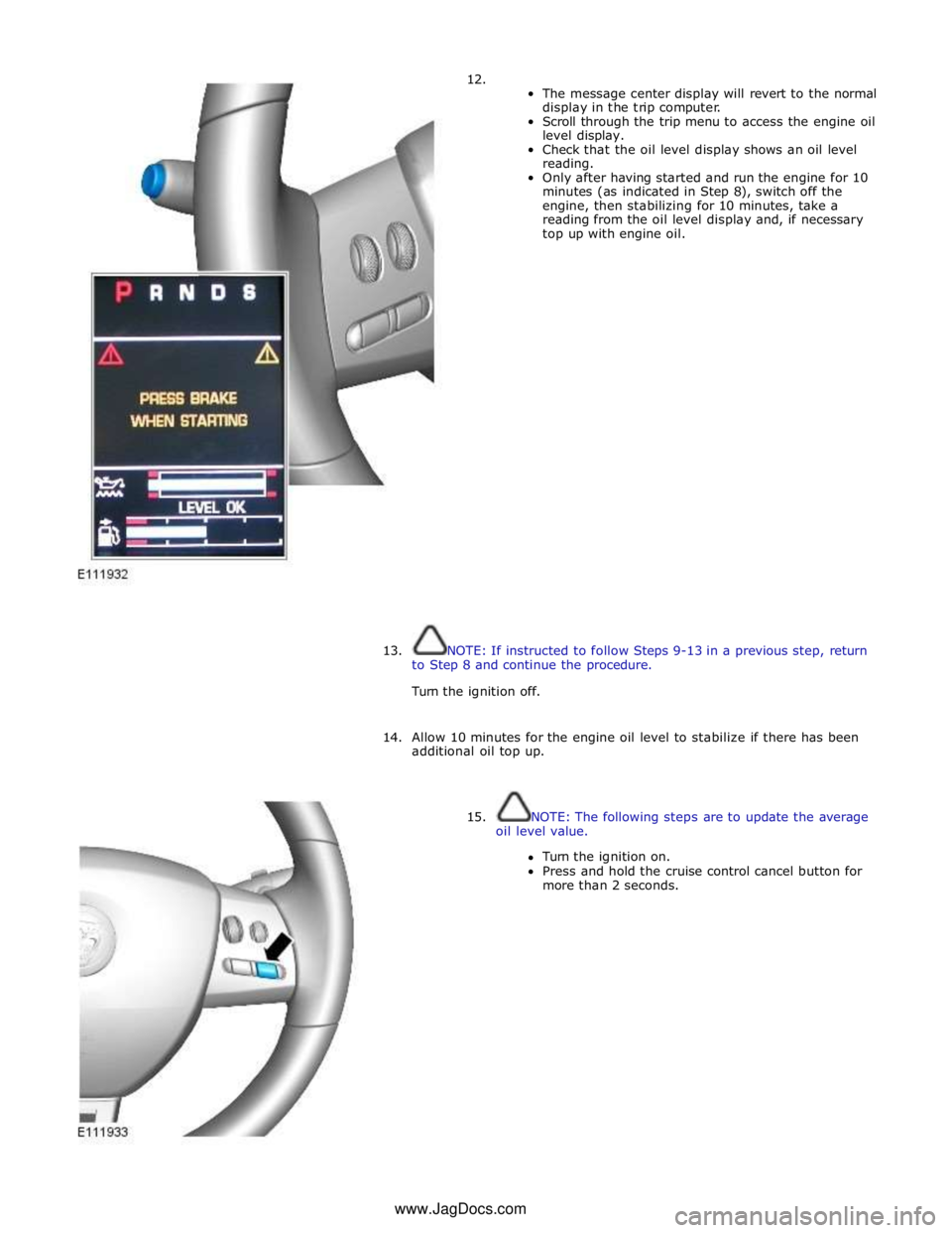
12.
The message center display will revert to the normal
display in the trip computer.
Scroll through the trip menu to access the engine oil
level display.
Check that the oil level display shows an oil level
reading.
Only after having started and run the engine for 10
minutes (as indicated in Step 8), switch off the
engine, then stabilizing for 10 minutes, take a
reading from the oil level display and, if necessary
top up with engine oil.
13. NOTE: If instructed to follow Steps 9-13 in a previous step, return
to Step 8 and continue the procedure.
Turn the ignition off.
14. Allow 10 minutes for the engine oil level to stabilize if there has been
additional oil top up.
15. NOTE: The following steps are to update the average
oil level value.
Turn the ignition on.
Press and hold the cruise control cancel button for
more than 2 seconds. www.JagDocs.com
Page 883 of 3039
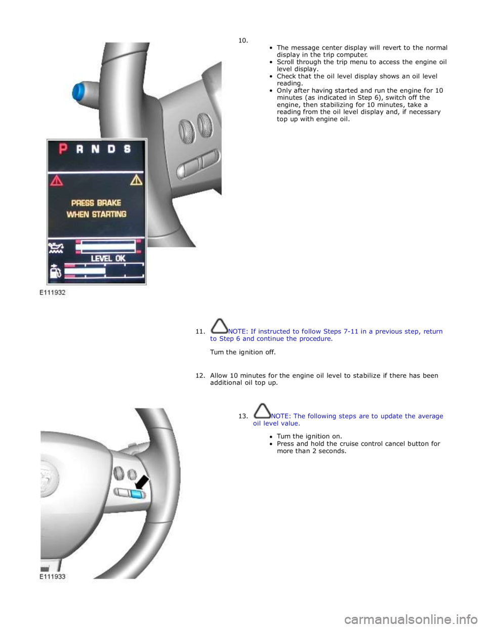
10.
The message center display will revert to the normal
display in the trip computer.
Scroll through the trip menu to access the engine oil
level display.
Check that the oil level display shows an oil level
reading.
Only after having started and run the engine for 10
minutes (as indicated in Step 6), switch off the
engine, then stabilizing for 10 minutes, take a
reading from the oil level display and, if necessary
top up with engine oil.
11. NOTE: If instructed to follow Steps 7-11 in a previous step, return
to Step 6 and continue the procedure.
Turn the ignition off.
12. Allow 10 minutes for the engine oil level to stabilize if there has been
additional oil top up.
13. NOTE: The following steps are to update the average
oil level value.
Turn the ignition on.
Press and hold the cruise control cancel button for
more than 2 seconds.
Page 891 of 3039
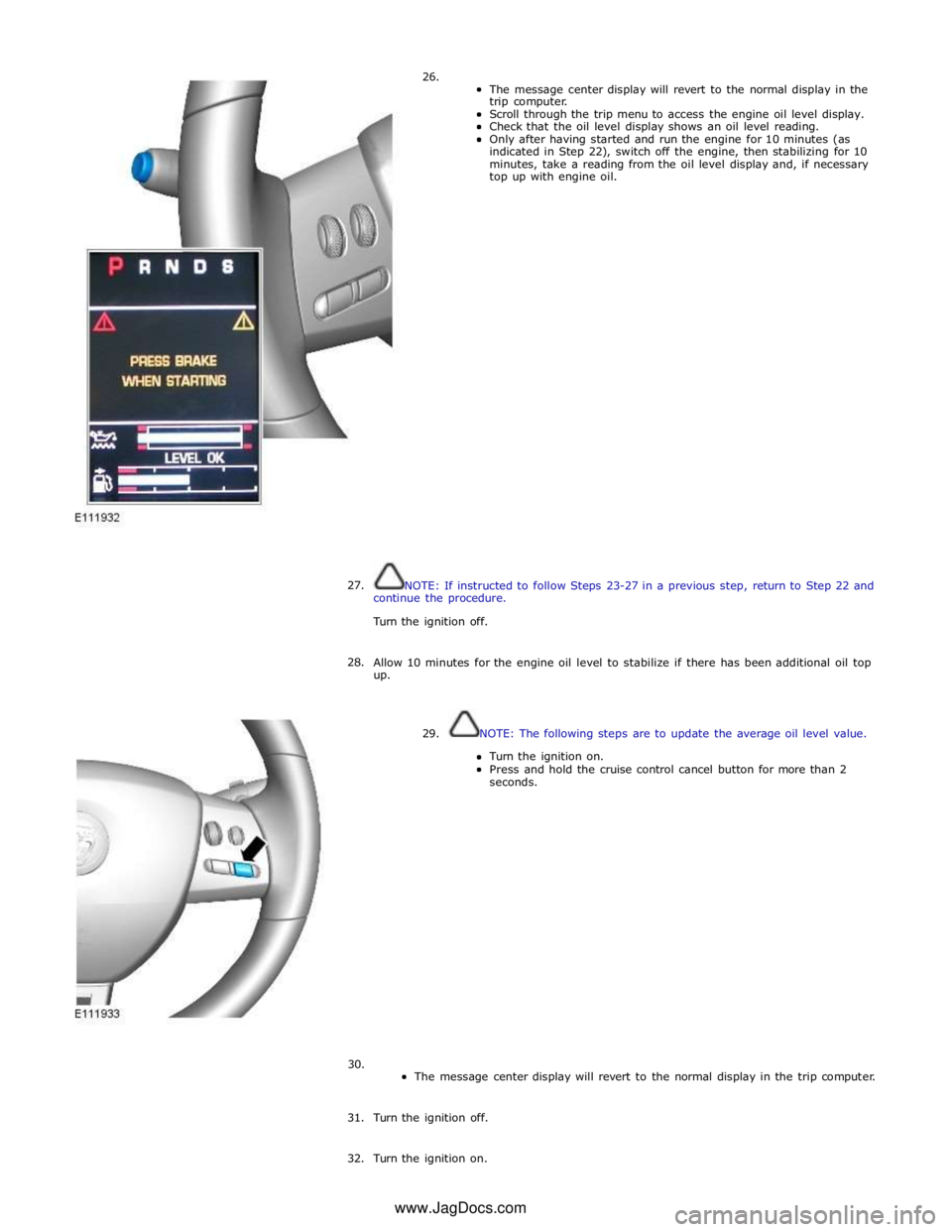
26.
The message center display will revert to the normal display in the
trip computer.
Scroll through the trip menu to access the engine oil level display.
Check that the oil level display shows an oil level reading.
Only after having started and run the engine for 10 minutes (as
indicated in Step 22), switch off the engine, then stabilizing for 10
minutes, take a reading from the oil level display and, if necessary
top up with engine oil.
27.
NOTE: If instructed to follow Steps 23-27 in a previous step, return to Step 22 and
continue the procedure.
Turn the ignition off.
28.
Allow 10 minutes for the engine oil level to stabilize if there has been additional oil top
up.
29. NOTE: The following steps are to update the average oil level value.
Turn the ignition on.
Press and hold the cruise control cancel button for more than 2
seconds.
30.
The message center display will revert to the normal display in the trip computer.
31. Turn the ignition off.
32. Turn the ignition on. www.JagDocs.com
Page 896 of 3039
Refer to: Specifications (303-01D Engine - V8 S/C 5.0L Petrol, Specifications).
Clean any residual engine oil from the oil filler cap area.
13. CAUTION: Make sure that the vehicle has been left for 5 minutes
from filling with oil.
Follow the Steps 15-19 before starting the engine.
14.
Start the engine and allow to run for 10 minutes, stop the
engine.
Check for leaks.
15. CAUTIONS:
Make sure that the selector lever and the gearshift mechanism are
in the park (P) position.
Make sure that the hood is open.
Turn the ignition on.
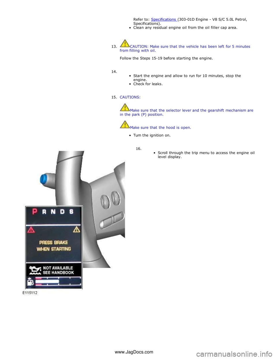
16.
Scroll through the trip menu to access the engine oil
level display. www.JagDocs.com