low oil pressure JAGUAR XFR 2010 1.G Owner's Manual
[x] Cancel search | Manufacturer: JAGUAR, Model Year: 2010, Model line: XFR, Model: JAGUAR XFR 2010 1.GPages: 3039, PDF Size: 58.49 MB
Page 1181 of 3039
to deliver the correct mass of fuel to the combustion chambers.
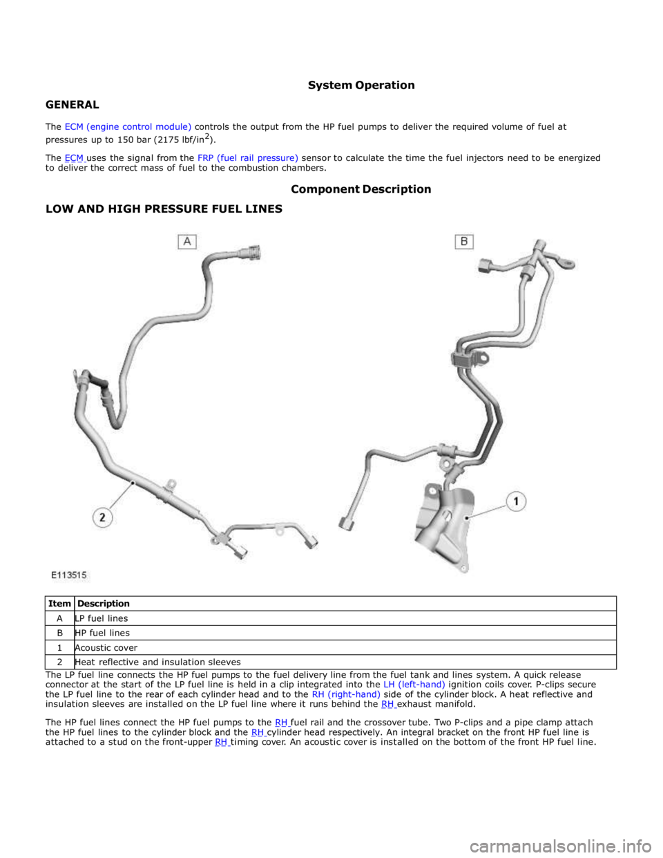
LOW AND HIGH PRESSURE FUEL LINES Component Description
Item Description A LP fuel lines B HP fuel lines 1 Acoustic cover 2 Heat reflective and insulation sleeves The LP fuel line connects the HP fuel pumps to the fuel delivery line from the fuel tank and lines system. A quick release
connector at the start of the LP fuel line is held in a clip integrated into the LH (left-hand) ignition coils cover. P-clips secure
the LP fuel line to the rear of each cylinder head and to the RH (right-hand) side of the cylinder block. A heat reflective and
insulation sleeves are installed on the LP fuel line where it runs behind the RH exhaust manifold.
The HP fuel lines connect the HP fuel pumps to the RH fuel rail and the crossover tube. Two P-clips and a pipe clamp attach the HP fuel lines to the cylinder block and the RH cylinder head respectively. An integral bracket on the front HP fuel line is attached to a stud on the front-upper RH timing cover. An acoustic cover is installed on the bottom of the front HP fuel line.
Page 1361 of 3039
DIAGNOSTICS
The ECM stores each fault as a DTC (diagnostic trouble code). The DTC and associated environmental and freeze frame data can be read using Jaguar approved diagnostic equipment, which can also read real time data from each sensor, the adaption
values currently being employed and the current fueling, ignition and idle speed settings.
ENGINE CONTROL MODULE Component Description
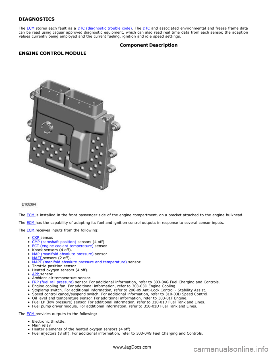
The ECM is installed in the front passenger side of the engine compartment, on a bracket attached to the engine bulkhead. The ECM has the capability of adapting its fuel and ignition control outputs in response to several sensor inputs. The ECM receives inputs from the following:
CKP sensor. CMP (camshaft position) sensors (4 off).
ECT (engine coolant temperature) sensor.
Knock sensors (4 off).
MAP (manifold absolute pressure) sensor.
MAFT sensors (2 off). MAPT (manifold absolute pressure and temperature) sensor.
Throttle position sensor.
Heated oxygen sensors (4 off).
APP sensor. Ambient air temperature sensor.
FRP (fuel rail pressure) sensor. For additional information, refer to 303-04G Fuel Charging and Controls.
Engine cooling fan. For additional information, refer to 303-03D Engine Cooling.
Stoplamp switch. For additional information, refer to 206-09 Anti-Lock Control - Stability Assist.
Speed control cancel/suspend switch. For additional information, refer to 310-03D Speed Control.
Oil level and temperature sensor. For additional information, refer to 303-01F Engine.
Fuel LP (low pressure) sensor. For additional information, refer to 310-01D Fuel Tank and Lines.
Fuel pump driver module. For additional information, refer to 310-01D Fuel Tank and Lines.
The ECM provides outputs to the following: Electronic throttle.
Main relay.
Heater elements of the heated oxygen sensors (4 off).
Fuel injectors (8 off). For additional information, refer to 303-04G Fuel Charging and Controls. www.JagDocs.com
Page 1429 of 3039
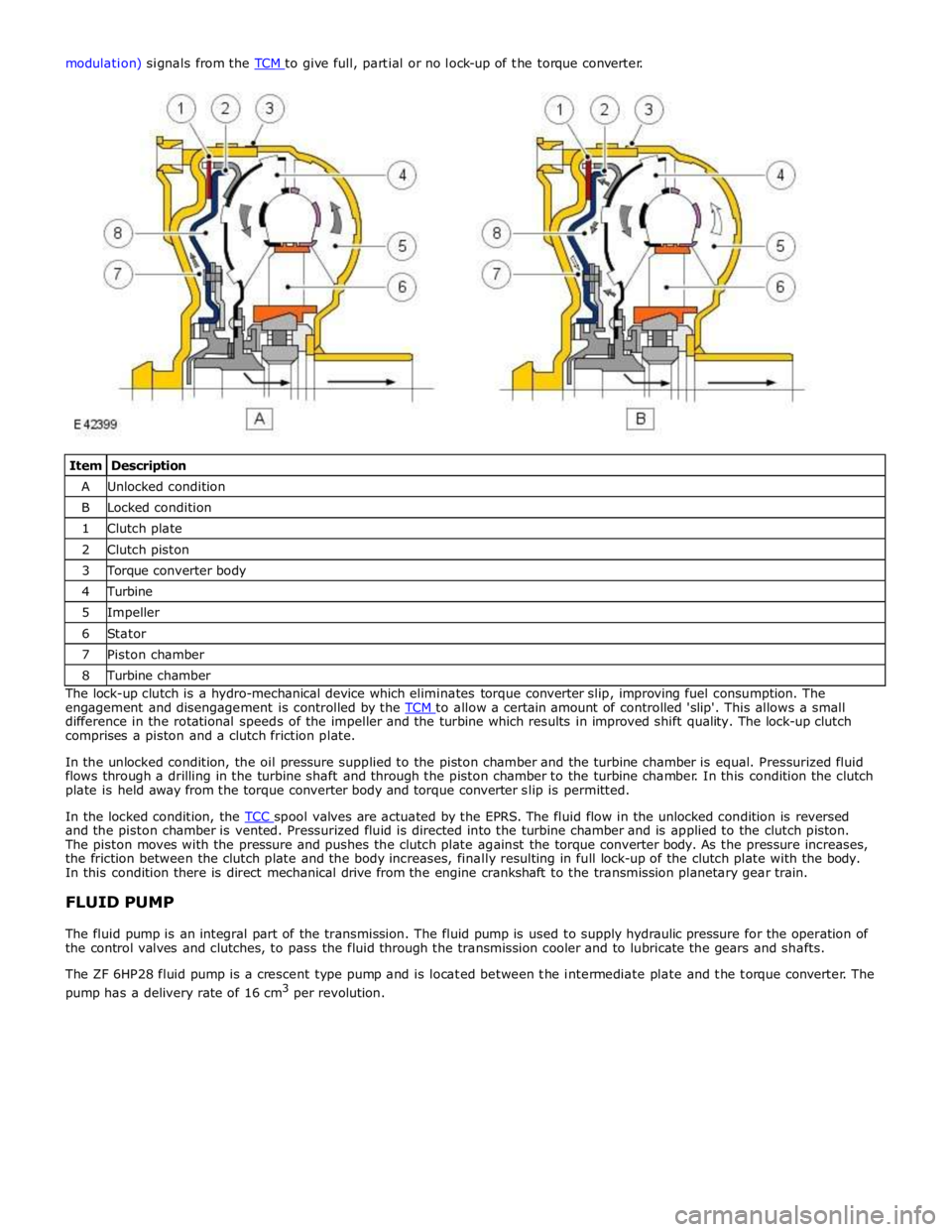
Item Description A Unlocked condition B Locked condition 1 Clutch plate 2 Clutch piston 3 Torque converter body 4 Turbine 5 Impeller 6 Stator 7 Piston chamber 8 Turbine chamber The lock-up clutch is a hydro-mechanical device which eliminates torque converter slip, improving fuel consumption. The
engagement and disengagement is controlled by the TCM to allow a certain amount of controlled 'slip'. This allows a small difference in the rotational speeds of the impeller and the turbine which results in improved shift quality. The lock-up clutch
comprises a piston and a clutch friction plate.
In the unlocked condition, the oil pressure supplied to the piston chamber and the turbine chamber is equal. Pressurized fluid
flows through a drilling in the turbine shaft and through the piston chamber to the turbine chamber. In this condition the clutch
plate is held away from the torque converter body and torque converter slip is permitted.
In the locked condition, the TCC spool valves are actuated by the EPRS. The fluid flow in the unlocked condition is reversed and the piston chamber is vented. Pressurized fluid is directed into the turbine chamber and is applied to the clutch piston.
The piston moves with the pressure and pushes the clutch plate against the torque converter body. As the pressure increases,
the friction between the clutch plate and the body increases, finally resulting in full lock-up of the clutch plate with the body.
In this condition there is direct mechanical drive from the engine crankshaft to the transmission planetary gear train.
FLUID PUMP
The fluid pump is an integral part of the transmission. The fluid pump is used to supply hydraulic pressure for the operation of
the control valves and clutches, to pass the fluid through the transmission cooler and to lubricate the gears and shafts.
The ZF 6HP28 fluid pump is a crescent type pump and is located between the intermediate plate and the torque converter. The
pump has a delivery rate of 16 cm3
per revolution.
Page 1430 of 3039

1 Securing ring 2 Shaft oil seal 3 O-ring seal 4 Pump housing 5 Ring gear 6 Crescent spacer 7 Roller bearing 8 Impeller 9 Centering pin 10 Spring washer 11 Outlet port (high pressure) 12 Inlet port (low pressure) The pump comprises a housing, a crescent spacer, an impeller and a ring gear. The housing has inlet and outlet ports to direct
flow and is located in the intermediate plate by a centering pin. The pump action is achieved by the impeller, ring gear and
crescent spacer.
The crescent spacer is fixed in its position by a pin and is located between the ring gear and the impeller. The impeller is
driven by drive from the torque converter hub which is located on a needle roller bearing in the pump housing. The impeller
teeth mesh with those of the ring gear. When the impeller is rotated, the motion is transferred to the ring gear which rotates
in the same direction.
The rotational motion of the ring gear and the impeller collects fluid from the intake port in the spaces between the teeth.
When the teeth reach the crescent spacer, the oil is trapped in the spaces between the teeth and is carried with the rotation
of the gears. The spacer tapers near the outlet port. This reduces the space between the gear teeth causing a build up of fluid
pressure as the oil reaches the outlet port. When the teeth pass the end of the spacer the pressurized fluid is released into
the outlet port.
The fluid emerging from the outlet port is passed through the fluid pressure control valve. At high operating speeds the
pressure control valve maintains the output pressure to the gearbox at a predetermined maximum level. Excess fluid is
relieved from the pressure control valve and is directed, via the main pressure valve in the valve block, back to the pump inlet
port. This provides a pressurized feed to the pump inlet which prevents cavitation and reduces pump noise.
Page 1435 of 3039
Published: 25-Aug-2011
Automatic Transmission/Transaxle - TDV6 3.0L Diesel /V8 5.0L Petrol/V8 S/C 5.0L Petrol - Diagnostics
Diagnosis and Testing
Principle of Operation
For a detailed description of the automatic transmission/transaxle, refer to the relevant Description and Operation section n
the workshop manual. REFER to: (307-01B Automatic Transmission/Transaxle - TDV6 3.0L Diesel /V8 5.0L Petrol/V8 S/C 5.0L
Petrol)
Transmission Description (Description and Operation), Transmission Description (Description and Operation), Transmission Description (Description and Operation).
Fluid Level and Condition Check
CAUTION: The vehicle should not be driven if the fluid level is low as internal failure can result.
NOTE: The transmission fluid temperature must not be allowed to exceed 50°C (122°F) whilst checking level. Should the
temperature rise above this figure, abort the check and allow the transmission fluid to cool to below 30°C (86°F).
This vehicle is not equipped with a fluid level indicator. An incorrect level may affect the transmission operation and could
result in transmission damage. To correctly check and add fluid to the transmission.
REFER to: Transmission Fluid Level Check (307-01B Automatic Transmission/Transaxle - TDV6 3.0L Diesel /V8 5.0L Petrol/V8 S/C 5.0L Petrol, General Procedures).
High Fluid Level
A fluid level that is too high may cause the fluid to become aerated due to the churning action of the rotating internal parts.
This will cause erratic control pressure, foaming, loss of fluid from the vent tube and possible transmission damage. If an
overfill condition is identified, with the engine at idle ensure the fluid temperature is within the specified range and allow the
excess fluid to drain until a small thread of fluid runs from the filler/level plug hole.
Low Fluid Level
A low fluid level could result in poor transmission engagement, slipping, or damage. This could also indicate a leak in one of
the transmission seals or gaskets.
REFER to: Transmission Fluid Level Check (307-01B Automatic Transmission/Transaxle - TDV6 3.0L Diesel /V8 5.0L Petrol/V8 S/C 5.0L Petrol, General Procedures).
Adding Fluid
CAUTION: The use of any other type of transmission fluid other than that specified can result in transmission damage.
If fluid needs to be added, add fluid in 0.50 liter increments through the fill hole Opening. Do not overfill the fluid. For fluid
type, refer to the General Specification chart in this section.
REFER to: Specifications (307-01B Automatic Transmission/Transaxle - TDV6 3.0L Diesel /V8 5.0L Petrol/V8 S/C 5.0L Petrol, Specifications).
Fluid Condition Check
1. Check the fluid level.
REFER to: Transmission Fluid Level Check (307-01B Automatic Transmission/Transaxle - TDV6 3.0L Diesel /V8 5.0L Petrol/V8 S/C 5.0L Petrol, General Procedures).
2. Observe the color and the odor of the fluid. The color under normal circumstances should be Honey.
3. Allow the fluid to drip onto a facial tissue and examine the stain.
4. If evidence of solid material is found, the transmission fluid pan should be removed for further inspection.
NOTE: In the event of a transmission unit replacement for internal failure, the oil cooler and pipes must also be replaced.
Inspection and Verification
1. Verify the customer concern.
2. Visually inspect for obvious signs of damage and system integrity.
Page 1441 of 3039

DTC Description Possible Cause Action P0781-07
1-2 Shift - Mechanical
Failures
Gear Ratio Monitoring.
Mechanical Failures Check and correct oil level. Clear DTC. If code
re-detects suspect Transmission (Gearbox) internal
fault. Install a new Transmission as required, refer to
the new module/component installation note at the top of the DTC Index P0781-77
2-1 Shift - commanded
position not reachable
Gear Ratio Monitoring.
Mechanical Failures Check and correct oil level. Clear DTC. If code
re-detects suspect Transmission (Gearbox) internal
fault. Install a new Transmission as required, refer to
the new module/component installation note at the top of the DTC Index P0782-07
2-3 Shift - commanded
position not reachable
Gear Ratio Monitoring.
Mechanical Failures Check and correct oil level. Clear DTC. If code
re-detects suspect Transmission (Gearbox) internal
fault. Install a new Transmission as required, refer to
the new module/component installation note at the top of the DTC Index P0782-77
3-2 Shift - commanded
position not reachable
Gear Ratio Monitoring.
Mechanical Failures Check and correct oil level. Clear DTC. If code
re-detects suspect Transmission (Gearbox) internal
fault. Install a new Transmission as required, refer to
the new module/component installation note at the top of the DTC Index P0783-07
3-4 Shift - Mechanical
Failures
Gear Ratio Monitoring.
Mechanical Failures Check and correct oil level. Clear DTC. If code
re-detects suspect Transmission (Gearbox) internal
fault. Install a new Transmission as required, refer to
the new module/component installation note at the top of the DTC Index P0783-77
3-4 Shift - commanded
position not reachable
Gear Ratio Monitoring.
Mechanical Failures Check and correct oil level. Clear DTC. If code
re-detects suspect Transmission (Gearbox) internal
fault. Install a new Transmission as required, refer to
the new module/component installation note at the top of the DTC Index P0784-07
4-5 Shift - Mechanical
Failures
Gear Ratio Monitoring.
Mechanical Failures Check and correct oil level. Clear DTC. If code
re-detects suspect Transmission (Gearbox) internal
fault. Install a new Transmission as required, refer to
the new module/component installation note at the top of the DTC Index P0784-77
4-5 Shift - commanded
position not reachable
Gear Ratio Monitoring.
Mechanical Failures Check and correct oil level. Clear DTC. If code
re-detects suspect Transmission (Gearbox) internal
fault. Install a new Transmission as required, refer to
the new module/component installation note at the top of the DTC Index P0798-1A
Pressure Control Solenoid C
Electrical - Circuit Resistance
Below Threshold
Pressure control solenoid
C Circuit resistance
below threshold Suspect the Transmission control module. Install a
new Transmission control module as required, refer to
the new module/component installation note at the
top of the DTC Index P0798-1E
Pressure Control Solenoid C
Electrical - Circuit Short to
Ground
Pressure control solenoid
C electrical circuit short
to ground Suspect the Transmission control module. Install a
new Transmission control module as required, refer to
the new module/component installation note at the
top of the DTC Index P0798-21
Pressure Control Solenoid C
Electrical - signal amplitude
< minimum
Pressure Control Solenoid
C Electrical signal
amplitude < minimum Suspect the Transmission control module. Install a
new Transmission control module as required, refer to
the new module/component installation note at the
top of the DTC Index P0814-62 Transmission Range Display
Circuit - signal compare
failure
Transmission Range
Display Circuit signal
compare failure Suspect the Transmission control module. Install a
new Transmission control module as required, refer to
the new module/component installation note at the
top of the DTC Index P0826-08
Up and Down Switch circuit -
Bus Signal Message Failures
Invalid CAN signal from
BCM/Instrument cluster
Stuck switch
CAN bus circuit fault Check Central junction box and Instrument cluster for
stored DTCs. Check gear change switches for correct
operation. Refer to circuit diagrams and check CAN bus
for a circuit fault P0826-81
Up and Down Switch Circuit -
invalid serial data received
Invalid Can signal from
BCM / Instrument cluster
Stuck switch
CAN Bus Circuit fault Check Central junction box and Instrument cluster for
stored DTCs. Check Gear Change Switches for correct
operation. Refer to Circuit diagrams and check CAN
Bus for Circuit fault P0826-88
Up and Down Switch Circuit -
Bus off
SWM to BCM /
Instrument cluster LIN
Bus failure Check Central junction box and Steering Wheel Ice
Switches for stored DTCs. Refer to Circuit diagrams
and check LIN Bus for Circuit fault
Page 1442 of 3039

DTC Description Possible Cause Action P0829-07
5-6 Shift - Mechanical
Failures
Gear Ratio Monitoring.
Mechanical Failures Check and correct oil level. Clear DTC. If code
re-detects suspect Transmission internal fault. Install
a new Transmission as required, refer to the new
module/component installation note at the top of the
DTC Index P0829-77
6-5 Shift - Commanded
Position Not Reachable
Gear Ratio Monitoring.
Mechanical Failures Check and correct oil level. Clear DTC. If code
re-detects suspect Transmission internal fault. Install
a new Transmission as required, refer to the new
module/component installation note at the top of the
DTC Index P084F-01
Park / Neutral Switch Input
Circuit - General Electrical
Failure
Wrong voltage level
detected on Park/No Park
signal Check for correct output at Transmission control
module park signal pin (check in all positions) 12 volts
in Park, 0 volts in all other positions. If fault
identified, suspect the Transmission control module.
Install a new Transmission control module as required,
refer to the new module/component installation note
at the top of the DTC Index. If no fault identified,
check Park signal circuit to Transmission Shift Module
for short, open circuit. P0850-01
Park / Neutral Switch Input
Circuit - General Electrical
Failure
General electrical failure Suspect the Transmission control module. Install a
new Transmission control module as required, refer to
the new module/component installation note at the top of the DTC Index P0850-02
Park / Neutral Switch Input
Circuit - General signal
failure
General signal failure Check park lock mechanism. If park lock operation is
correct, suspect the transmission control module.
Check and install a new transmission control module
as required. Refer to the warranty policy and
procedures manual, or determine if any prior approval
programme is in operation, prior to the installation of
a new module/component P0850-29
Park / Neutral Switch Input
Circuit - signal invalid
Signal invalid Check park lock mechanism. If park lock operation is
correct, suspect the transmission control module.
Check and install a new transmission control module
as required. Refer to the warranty policy and
procedures manual, or determine if any prior approval
programme is in operation, prior to the installation of
a new module/component P850-1C
Park / Neutral Switch Input
Circuit - circuit voltage out
of range
Circuit voltage out of
range Check park lock mechanism, if park lock operation
correct suspect the Transmission control module.
Install a new Transmission control module as required,
refer to the new module/component installation note
at the top of the DTC Index P0919-93
Gear Shift Position Control
Error - no operation
No shifting despite driver
request Suspect the Transmission control module. Install a
new Transmission control module as required, refer to
the new module/component installation note at the top of the DTC Index P0919-94
Gear Shift Position Control
Error - unexpected operation
Shifting without driver
request Suspect the Transmission control module. Install a
new Transmission control module as required, refer to
the new module/component installation note at the top of the DTC Index P0938-29
Hydraulic Oil Temperature
Sensor Range/Performance -
signal invalid
Transmission fluid
temperature compared
with module temperature
fault Clear DTC. Carry out cold start road test, continue
driving vehicle until normal operating temperature is
achieved. Read DTCs, if DTC returns, suspect the
Transmission control module. Install a new
Transmission control module as required, refer to the
new module/component installation note at the top of
the DTC Index P0963-12
Pressure Control Solenoid A
Control Circuit High - Circuit
Short to Battery
Pressure control solenoid
1 Circuit Short to Power Suspect the Transmission control module. Install a
new Transmission control module as required, refer to
the new module/component installation note at the top of the DTC Index P0964-13
Pressure Control Solenoid B
Control Circuit / Open -
Circuit Open
Pressure Control Solenoid
B Control Circuit Open Suspect the Transmission control module. Install a
new Transmission control module as required, refer to
the new module/component installation note at the top of the DTC Index P0964-14
Pressure Control Solenoid B
Control Circuit / Open -
Circuit Short to Ground or
Open
Pressure Control Solenoid
B Control Circuit Short to
Ground or Open Suspect the Transmission control module. Install a
new Transmission control module as required, refer to
the new module/component installation note at the
top of the DTC Index P0966-11
Pressure Control Solenoid B
Control Circuit Low - Circuit
Short to Ground
Pressure control solenoid
2 Circuit Short to Ground Suspect the Transmission control module. Install a
new Transmission control module as required, refer to
the new module/component installation note at the top of the DTC Index www.JagDocs.com
Page 1444 of 3039

DTC Description Possible Cause Action P1707-77 Transfer Case Neutral or
Park/Neutral Indication
Circuit - commanded
position not reachable
Commanded position not
reachable Clear the DTC. Test drive the Vehicle, engaging and
disengaging the parking lock several times. If the DTC
recurs, check parking lock components and replace as
required. If no faulty park lock component is found
Clear DTC and the DTC returns suspect the
Transmission control module. Install a new
Transmission control module as required, refer to the
new module/component installation note at the top of
the DTC Index P2700-07 Transmission Friction
Element A Apply Time
Range/Performance -
Mechanical Failures
Gear Ratio Monitoring.
Mechanical Failures Check and correct oil level. Clear DTC. If code
re-detects suspect Transmission (Gearbox) internal
fault. Install a new Transmission as required, refer to
the new module/component installation note at the top of the DTC Index P2701-07 Transmission Friction
Element B Apply Time
Range/Performance -
Mechanical Failures
Gear Ratio Monitoring.
Mechanical Failures Check and correct oil level. Clear DTC. If code
re-detects suspect Transmission (Gearbox) internal
fault. Install a new Transmission as required, refer to
the new module/component installation note at the top of the DTC Index P2702-07 Transmission Friction
Element C Apply Time
Range/Performance -
Mechanical Failures
Gear Ratio Monitoring.
Mechanical Failures Check and correct oil level. Clear DTC. If code
re-detects suspect Transmission (Gearbox) internal
fault. Install a new Transmission as required, refer to
the new module/component installation note at the top of the DTC Index P2703-07 Transmission Friction
Element D Apply Time
Range/Performance -
Mechanical Failures
Gear Ratio Monitoring.
Mechanical Failures Check and correct oil level. Clear DTC. If code
re-detects suspect Transmission (Gearbox) internal
fault. Install a new Transmission as required, refer to
the new module/component installation note at the top of the DTC Index P2704-07 Transmission Friction
Element E Apply Time
Range/Performance -
Mechanical Failures
Gear Ratio Monitoring.
Mechanical Failures Check and correct oil level. Clear DTC. If code
re-detects suspect Transmission (Gearbox) internal
fault. Install a new Transmission as required, refer to
the new module/component installation note at the top of the DTC Index P2713-04 Pressure Control Solenoid D
- System Internal Failures
System internal failures Suspect the Transmission control module. Install a
new Transmission control module as required, refer to
the new module/component installation note at the top of the DTC Index P2713-48 Pressure Control Solenoid D
- Supervision Software
Failure
Supervision software
failure Suspect the Transmission control module. Install a
new Transmission control module as required, refer to
the new module/component installation note at the top of the DTC Index P2716-22
Pressure Control Solenoid D
Electrical - signal amplitude
> maximum
Pressure Control Solenoid
D Electrical signal
amplitude > maximum Suspect the Transmission control module. Install a
new Transmission control module as required, refer to
the new module/component installation note at the
top of the DTC Index P2716-1A
Pressure Control Solenoid D
Electrical - Circuit Resistance
Below Threshold
Pressure control solenoid
D circuit resistance below
threshold Suspect the Transmission control module. Install a
new Transmission control module as required, refer to
the new module/component installation note at the
top of the DTC Index P2716-1E
Pressure Control Solenoid D
Electrical - Circuit Resistance
Out Of Range
Pressure control solenoid
D circuit resistance out
of range Suspect the Transmission control module. Install a
new Transmission control module as required, refer to
the new module/component installation note at the
top of the DTC Index P2718-14
Pressure Control Solenoid D
Control Circuit / Open -
Circuit Short to Ground or
Open
Pressure control solenoid
D Circuit Short to Ground
or Open Circuit Suspect the Transmission control module. Install a
new Transmission control module as required, refer to
the new module/component installation note at the
top of the DTC Index P2720-11
Pressure Control Solenoid D
Control Circuit Low - Circuit
Short to Ground
Pressure control solenoid
D Circuit Short to Ground Suspect the Transmission control module. Install a
new Transmission control module as required, refer to
the new module/component installation note at the top of the DTC Index P2721-12
Pressure Control Solenoid D
Control Circuit High - Circuit
Short to Battery
Pressure control solenoid
D Circuit Short to Power Suspect the Transmission control module. Install a
new Transmission control module as required, refer to
the new module/component installation note at the top of the DTC Index P2722-04 Pressure Control Solenoid E
- System Internal Failures
Pressure Control Solenoid
E system internal failures Suspect the Transmission control module. Install a
new Transmission control module as required, refer to
the new module/component installation note at the top of the DTC Index
Page 1591 of 3039
1 Magnetic foil 2 Spacer 3 Ceramic surface 4 Magnet 5 Resistance film The film resistors are arranged in a linear arc with resistance ranging from 51.2 to 992.11 Ohms. The electrical output signal is
proportional to the amount of fuel in the tank and the position of the float arm. The measured resistance is processed by the
instrument cluster to implement an anti-slosh function. This monitors the signal and updates the fuel gauge pointer position
at regular intervals, preventing constant pointer movement caused by fuel movement in the tank due to cornering or braking.
A warning lamp is incorporated in the instrument cluster and illuminates when the fuel level is low.
The fuel level sender signal is converted into a CAN message by the instrument cluster as a direct interpretation of the fuel tank contents in liters. The ECM uses the CAN message to store additional OBD (on-board diagnostic) 'P' Codes for misfire detection when the fuel level is below a predetermined capacity.
JET PUMP
The fuel system incorporates two jet pumps. One jet pump is integrated into the fuel pump and draws fuel from the RH side of the fuel tank. The other jet pump is located on the fuel delivery module on the RH side of the tank. There is a pipe that is located in the LH side of the tank that allows fuel to be drawn over from the LH side of the tank, delivering fuel into the swirl pot. The jet pumps operate on a venturi effect created by the fuel at pump output pressure passing through the jet pump. This
draws additional fuel from the LH side of the tank through ports in the jet pump body, delivering additional fuel to the swirl pot.
FUEL VENT VALVE
The fuel level vent valve is located in the upper half of the tank and is connected into a separator which is connected to the
Roll Over Valve (ROV) tank breather. The main purpose of the fuel level vent valve is to control the fill volume of the tank.
During filling, air trapped inside the tank and a small amount of vapor is passed via the fuel level vent valve to the tank
breather. The air and vapor mix then vents to atmosphere through the breather. During filling, when the tank reaches its full
level, the fuel level vent valve closes and prevents air/vapor passing through to the tank breather. The resulting back pressure
causes refueling to stop automatically.
The fuel level vent valve is always open when the fuel tank is below full, providing an unrestricted air/vapor outlet to the tank
breather.
www.JagDocs.com
Page 1669 of 3039
8. WARNING: Refrigerant must always be recycled before re-use to ensure
that the purity of the refrigerantis high enough for safe use in the air
conditioning system. Recycling should always be carried out with
equipment which is design certified by Underwriter Laboratory Inc. for
compliance with SEA J1991. Other equipment may not recycle refrigerant
to the required level of purity. R143a Refrigerant Recover Recycling
Recharging station must not be used with any other type of
refrigerant.Refrigerant R134a from domestic and comercial sources must
not be used in motor vehicles air conditioning systems.
Allow the system to recover the refrigerant from the system.
9. Close the valves on the refrigerant station.
10. Turn the main switch 'OFF'.
11. Close the valves on the connections.
12. Disconnect the high and low pressure connections.
13. Install the dust covers to the connectors.
14. Open the tap at the rear of the station to drain the refrigerant oil.
15. Measure and record the quantity of refrigerant oil recovered from the
system.
16. Close the tap at the rear of the station.
17. Evacuation.
18. Remove the dust covers from the high and low pressure connections.
19. Connect the high and low pressure lines to the appropriate connections.
20. Open the valves on the connections.
21. Turn the valves on the station to the correct positions.
22. Turn the process switch to the correct position.
23. Turn the main switch to 'ON'.
24. Allow the station to evacuate the A/C system.
25. CAUTION: The system must be evacuated immediatley before
recharging commences. Delay between evacuation and recharging is not
permitted
Recharging
26. Close the valves on the refrigerant station.