oil temperature JAGUAR XFR 2010 1.G Owner's Manual
[x] Cancel search | Manufacturer: JAGUAR, Model Year: 2010, Model line: XFR, Model: JAGUAR XFR 2010 1.GPages: 3039, PDF Size: 58.49 MB
Page 869 of 3039
Operating Temperature Range -40 to 160 °C (-40 to 320 °F) Oil Level Check
For additional information, refer to Engine Oil Draining and Filling (303-01A, General Procedures).
For accuracy, oil level checks should be performed with the vehicle on level ground when the oil is hot. The vehicle needs to
stand for approximately 10 minutes, after the engine is switched off, to allow the oil to drain back into the sump pan and the
oil level to stabilize. The oil level system will not give a reading until the oil level has stabilized.
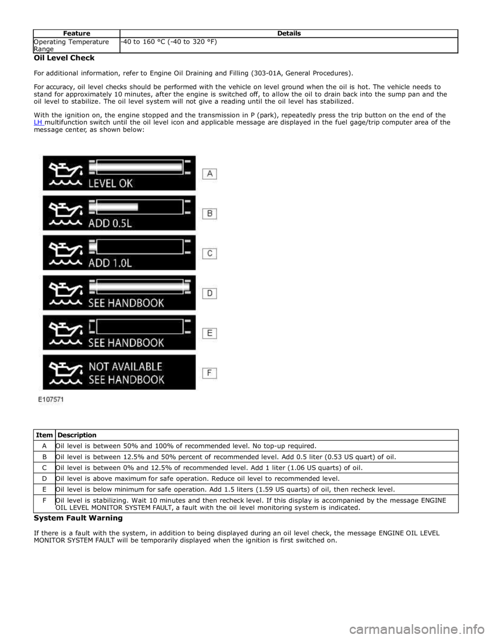
With the ignition on, the engine stopped and the transmission in P (park), repeatedly press the trip button on the end of the
LH multifunction switch until the oil level icon and applicable message are displayed in the fuel gage/trip computer area of the message center, as shown below:
Item Description A Oil level is between 50% and 100% of recommended level. No top-up required. B Oil level is between 12.5% and 50% percent of recommended level. Add 0.5 liter (0.53 US quart) of oil. C Oil level is between 0% and 12.5% of recommended level. Add 1 liter (1.06 US quarts) of oil. D Oil level is above maximum for safe operation. Reduce oil level to recommended level. E Oil level is below minimum for safe operation. Add 1.5 liters (1.59 US quarts) of oil, then recheck level. F Oil level is stabilizing. Wait 10 minutes and then recheck level. If this display is accompanied by the message ENGINE OIL LEVEL MONITOR SYSTEM FAULT, a fault with the oil level monitoring system is indicated. System Fault Warning
If there is a fault with the system, in addition to being displayed during an oil level check, the message ENGINE OIL LEVEL
MONITOR SYSTEM FAULT will be temporarily displayed when the ignition is first switched on.
Page 1111 of 3039

Published: 11-May-2011
Engine Cooling - V8 5.0L Petrol/V8 S/C 5.0L Petrol - Engine Cooling - Overview
Description and Operation
OVERVIEW
The engine cooling system maintains the engine within an optimum temperature range under changing ambient and engine
operating conditions. The system is a pressurized expansion tank system with continuous bleeds to separate air from the
coolant and prevent the formation of air locks. The engine cooling system also provides:
Heating for:
- The passenger compartment. For additional information, refer to 412-01 Climate Control.
- The throttle body.
Cooling for:
- The engine oil cooler. For additional information, refer to 303-01F Engine - 5.0L, Vehicles With: Supercharger or
303-01E Engine - 5.0L, Vehicles Without: Supercharger.
- The transmission fluid cooler. For additional information, refer to 307-02B Transmission/Transaxle Cooling -
5.0L/3.0L Diesel.
The primary components of the engine cooling system are the:
Coolant pump.
Thermostat.
Radiator.
Auxiliary radiator (SC (supercharger) vehicles only).
Cooling fan.
Expansion tank.
Engine oil cooler.
Outlet tube and heater manifold.
Connecting hoses and pipes.
Page 1114 of 3039
14 Radiator 15 Auxiliary radiator 16 Connection with supercharger cooling system
System Operation
When the engine is running, the coolant is circulated around the engine cooling system by the coolant pump. From the coolant
pump, coolant flows through the cylinder heads and the engine oil cooler into the cylinder block and the heater manifold.
In the cylinder block, the coolant flows forwards to the outlet tube. When the coolant is cold, the thermostat is closed and the
coolant flows direct from the outlet tube back to the coolant pump. Once the coolant reaches operating temperature the
thermostat begins to open, to control system temperature, and coolant flows from the outlet tube to the coolant pump via the
radiator and, on SC (supercharger) vehicles, the auxiliary radiator. When the thermostat is open, the coolant flow through the
radiator(s) also generates a coolant flow through the transmission fluid cooler.
From the heater manifold the coolant flows through the electronic throttle and the heater core, in parallel circuits that are
unaffected by the position of the thermostat. From the electronic throttle, the coolant merges with bleed coolant from the
coolant pump and the outlet tube and flows to the expansion tank. From the heater core, the coolant flows back to the inlet of
the coolant pump.
Expansion and contraction of the coolant is accommodated by an air space in the expansion tank and the compliance of the
flexible hoses.
If the coolant level in the expansion tank decreases below a predetermined value, the level sensor connects a ground to the
instrument cluster, which activates the appropriate warning. For additional information, refer to 413-01 Instrument Cluster.
The cooling fan is operated by a fan control module integrated into the cooling fan motor. The fan control module regulates the
voltage, and thus speed, of the cooling fan motor in response to a PWM (pulse width modulation) signal from the ECM (engine
control module).
The cooling fan receives a battery feed and an ignition feed from the EJB (engine junction box). The ignition feed is supplied
from the main relay in the EJB, which is controlled by the ECM.
The ECM calculates the required fan speed from the engine temperature, A/C (air conditioning) system pressure and transmission fluid temperature. Under hot operating conditions, the fan may continue to operate for 4 minutes after the engine
has been switched off.
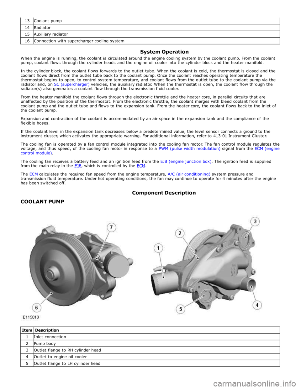
COOLANT PUMP Component Description
Item Description 1 Inlet connection 2 Pump body 3 Outlet flange to RH cylinder head 4 Outlet to engine oil cooler 5 Outlet flange to LH cylinder head
Page 1115 of 3039
7 Bleed pipe connection (containing check valve) The body of the coolant pump contains an impeller attached to a shaft supported in a bearing assembly. The impeller is driven
by a pulley, pressed on to the front of the shaft, which is driven by the accessory drive belt. For additional information, refer to
303-05E Accessory Drive - 5.0L, Vehicles Without: Supercharger or 303-05F - 5.0L, Vehicles With: Supercharger.
Two coolant outlet flanges attach the coolant pump to the front of the cylinder heads. A pipe connects a further coolant outlet
to a pipe from the engine oil cooler. A bleed connector is installed in the front of the coolant pump, adjacent to the coolant
inlet connection from the thermostat. A check valve is incorporated into the bleed connection.
THERMOSTAT
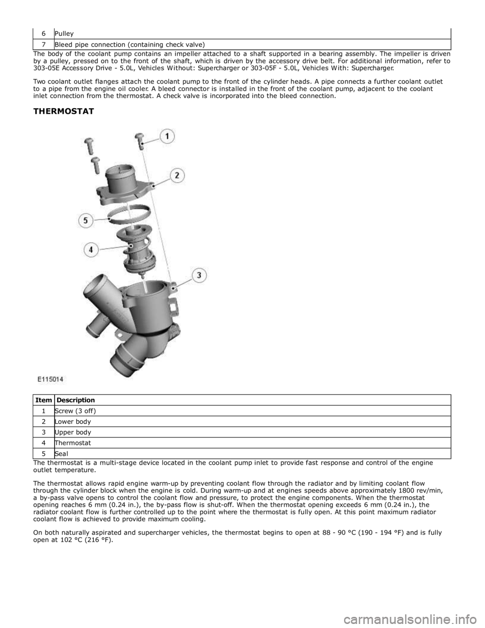
Item Description 1 Screw (3 off) 2 Lower body 3 Upper body 4 Thermostat 5 Seal The thermostat is a multi-stage device located in the coolant pump inlet to provide fast response and control of the engine
outlet temperature.
The thermostat allows rapid engine warm-up by preventing coolant flow through the radiator and by limiting coolant flow
through the cylinder block when the engine is cold. During warm-up and at engines speeds above approximately 1800 rev/min,
a by-pass valve opens to control the coolant flow and pressure, to protect the engine components. When the thermostat
opening reaches 6 mm (0.24 in.), the by-pass flow is shut-off. When the thermostat opening exceeds 6 mm (0.24 in.), the
radiator coolant flow is further controlled up to the point where the thermostat is fully open. At this point maximum radiator
coolant flow is achieved to provide maximum cooling.
On both naturally aspirated and supercharger vehicles, the thermostat begins to open at 88 - 90 °C (190 - 194 °F) and is fully
open at 102 °C (216 °F).
Page 1274 of 3039
GENERAL System Operation
The ignition coils are supplied with electrical power from the battery via a 250 A megafuse in the BJB (battery junction box)
and the ignition relay in the EJB (engine junction box). The control signal for the ignition relay is supplied by the CJB (central
junction box).
The ECM (engine control module) sends a separate signal to each ignition coil to trigger the power stage switching. The ECM calculates the dwell time from the battery voltage and engine speed, to ensure a constant energy level is produced in the
secondary coil each time the power stage is switched. This ensures sufficient spark energy is available without excessive
primary current flow, which avoids overheating and damage to the ignition coils.
The ECM calculates the ignition timing for individual cylinders from: Engine speed
Camshaft position
Engine load
Engine temperature
The knock control function
The shift control function
The idle speed control function.
IGNITION COILS Component Description
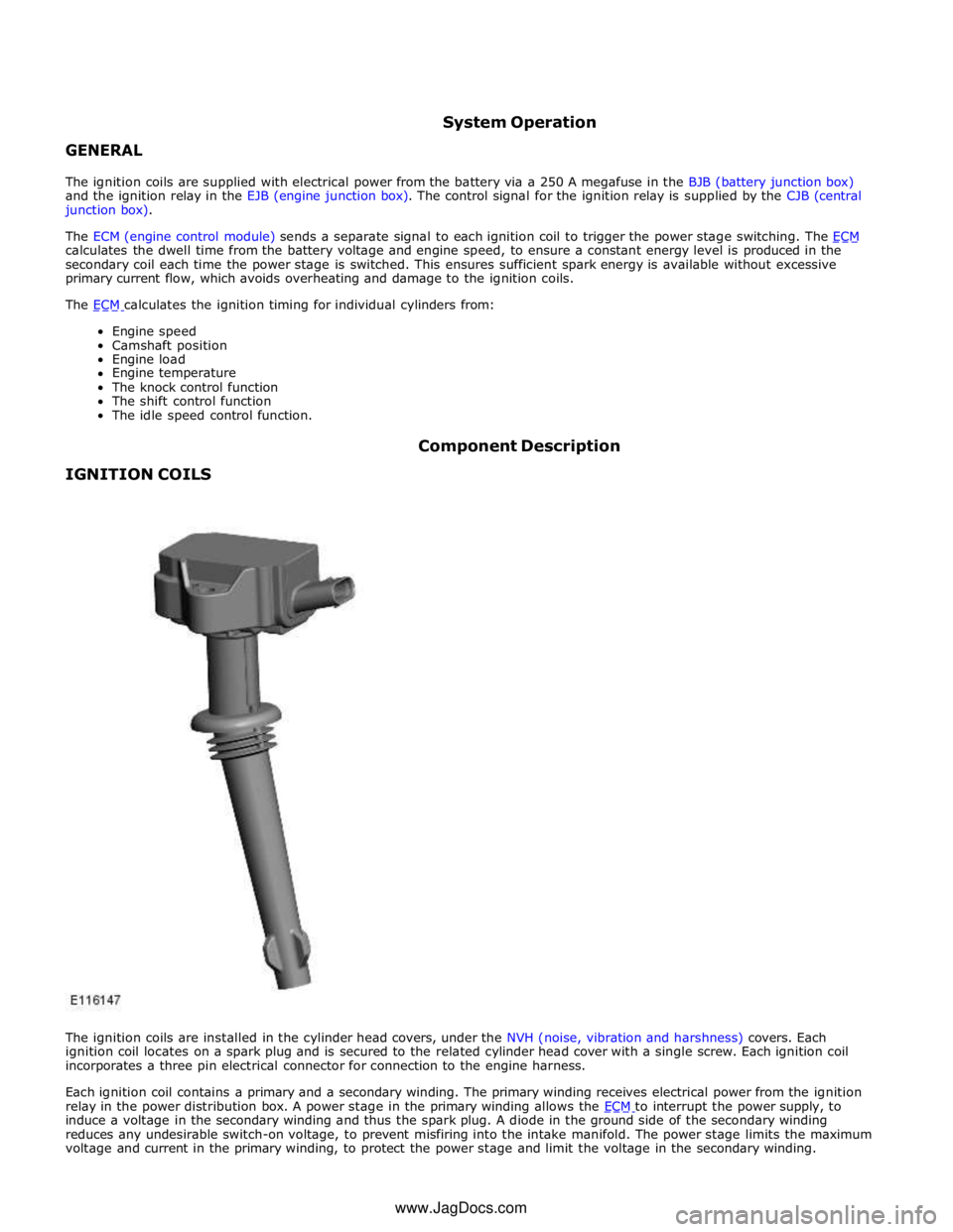
The ignition coils are installed in the cylinder head covers, under the NVH (noise, vibration and harshness) covers. Each
ignition coil locates on a spark plug and is secured to the related cylinder head cover with a single screw. Each ignition coil
incorporates a three pin electrical connector for connection to the engine harness.
Each ignition coil contains a primary and a secondary winding. The primary winding receives electrical power from the ignition
relay in the power distribution box. A power stage in the primary winding allows the ECM to interrupt the power supply, to induce a voltage in the secondary winding and thus the spark plug. A diode in the ground side of the secondary winding
reduces any undesirable switch-on voltage, to prevent misfiring into the intake manifold. The power stage limits the maximum
voltage and current in the primary winding, to protect the power stage and limit the voltage in the secondary winding. www.JagDocs.com
Page 1353 of 3039
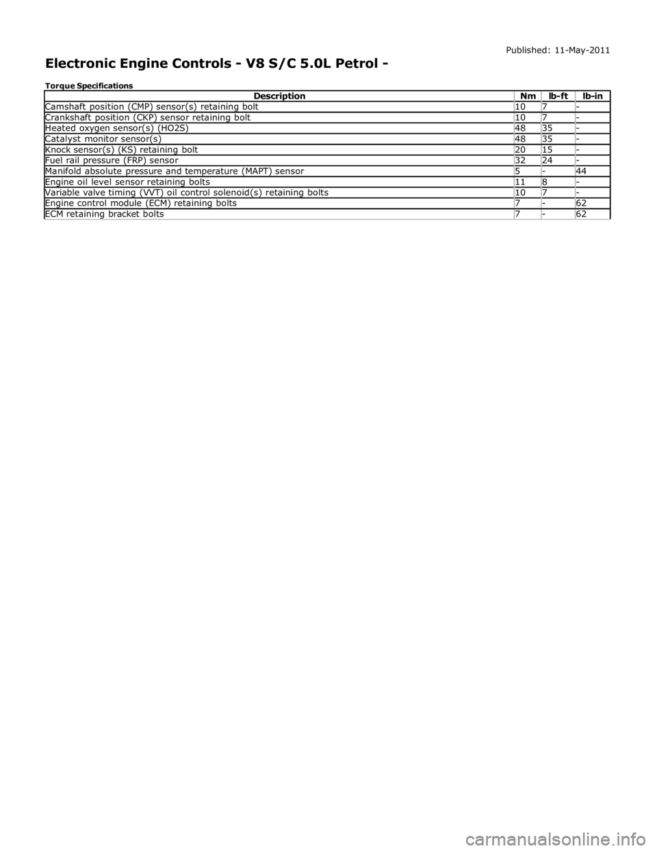
Camshaft position (CMP) sensor(s) retaining bolt 10 7 - Crankshaft position (CKP) sensor retaining bolt 10 7 - Heated oxygen sensor(s) (HO2S) 48 35 - Catalyst monitor sensor(s) 48 35 - Knock sensor(s) (KS) retaining bolt 20 15 - Fuel rail pressure (FRP) sensor 32 24 - Manifold absolute pressure and temperature (MAPT) sensor 5 - 44 Engine oil level sensor retaining bolts 11 8 - Variable valve timing (VVT) oil control solenoid(s) retaining bolts 10 7 - Engine control module (ECM) retaining bolts 7 - 62 ECM retaining bracket bolts 7 - 62
Page 1361 of 3039
DIAGNOSTICS
The ECM stores each fault as a DTC (diagnostic trouble code). The DTC and associated environmental and freeze frame data can be read using Jaguar approved diagnostic equipment, which can also read real time data from each sensor, the adaption
values currently being employed and the current fueling, ignition and idle speed settings.
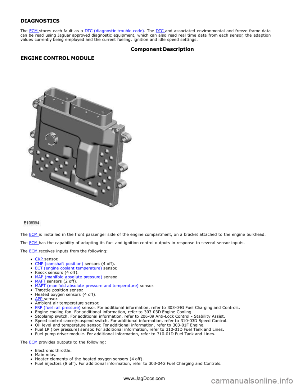
ENGINE CONTROL MODULE Component Description
The ECM is installed in the front passenger side of the engine compartment, on a bracket attached to the engine bulkhead. The ECM has the capability of adapting its fuel and ignition control outputs in response to several sensor inputs. The ECM receives inputs from the following:
CKP sensor. CMP (camshaft position) sensors (4 off).
ECT (engine coolant temperature) sensor.
Knock sensors (4 off).
MAP (manifold absolute pressure) sensor.
MAFT sensors (2 off). MAPT (manifold absolute pressure and temperature) sensor.
Throttle position sensor.
Heated oxygen sensors (4 off).
APP sensor. Ambient air temperature sensor.
FRP (fuel rail pressure) sensor. For additional information, refer to 303-04G Fuel Charging and Controls.
Engine cooling fan. For additional information, refer to 303-03D Engine Cooling.
Stoplamp switch. For additional information, refer to 206-09 Anti-Lock Control - Stability Assist.
Speed control cancel/suspend switch. For additional information, refer to 310-03D Speed Control.
Oil level and temperature sensor. For additional information, refer to 303-01F Engine.
Fuel LP (low pressure) sensor. For additional information, refer to 310-01D Fuel Tank and Lines.
Fuel pump driver module. For additional information, refer to 310-01D Fuel Tank and Lines.
The ECM provides outputs to the following: Electronic throttle.
Main relay.
Heater elements of the heated oxygen sensors (4 off).
Fuel injectors (8 off). For additional information, refer to 303-04G Fuel Charging and Controls. www.JagDocs.com
Page 1435 of 3039
Published: 25-Aug-2011
Automatic Transmission/Transaxle - TDV6 3.0L Diesel /V8 5.0L Petrol/V8 S/C 5.0L Petrol - Diagnostics
Diagnosis and Testing
Principle of Operation
For a detailed description of the automatic transmission/transaxle, refer to the relevant Description and Operation section n
the workshop manual. REFER to: (307-01B Automatic Transmission/Transaxle - TDV6 3.0L Diesel /V8 5.0L Petrol/V8 S/C 5.0L
Petrol)
Transmission Description (Description and Operation), Transmission Description (Description and Operation), Transmission Description (Description and Operation).
Fluid Level and Condition Check
CAUTION: The vehicle should not be driven if the fluid level is low as internal failure can result.
NOTE: The transmission fluid temperature must not be allowed to exceed 50°C (122°F) whilst checking level. Should the
temperature rise above this figure, abort the check and allow the transmission fluid to cool to below 30°C (86°F).
This vehicle is not equipped with a fluid level indicator. An incorrect level may affect the transmission operation and could
result in transmission damage. To correctly check and add fluid to the transmission.
REFER to: Transmission Fluid Level Check (307-01B Automatic Transmission/Transaxle - TDV6 3.0L Diesel /V8 5.0L Petrol/V8 S/C 5.0L Petrol, General Procedures).
High Fluid Level
A fluid level that is too high may cause the fluid to become aerated due to the churning action of the rotating internal parts.
This will cause erratic control pressure, foaming, loss of fluid from the vent tube and possible transmission damage. If an
overfill condition is identified, with the engine at idle ensure the fluid temperature is within the specified range and allow the
excess fluid to drain until a small thread of fluid runs from the filler/level plug hole.
Low Fluid Level
A low fluid level could result in poor transmission engagement, slipping, or damage. This could also indicate a leak in one of
the transmission seals or gaskets.
REFER to: Transmission Fluid Level Check (307-01B Automatic Transmission/Transaxle - TDV6 3.0L Diesel /V8 5.0L Petrol/V8 S/C 5.0L Petrol, General Procedures).
Adding Fluid
CAUTION: The use of any other type of transmission fluid other than that specified can result in transmission damage.
If fluid needs to be added, add fluid in 0.50 liter increments through the fill hole Opening. Do not overfill the fluid. For fluid
type, refer to the General Specification chart in this section.
REFER to: Specifications (307-01B Automatic Transmission/Transaxle - TDV6 3.0L Diesel /V8 5.0L Petrol/V8 S/C 5.0L Petrol, Specifications).
Fluid Condition Check
1. Check the fluid level.
REFER to: Transmission Fluid Level Check (307-01B Automatic Transmission/Transaxle - TDV6 3.0L Diesel /V8 5.0L Petrol/V8 S/C 5.0L Petrol, General Procedures).
2. Observe the color and the odor of the fluid. The color under normal circumstances should be Honey.
3. Allow the fluid to drip onto a facial tissue and examine the stain.
4. If evidence of solid material is found, the transmission fluid pan should be removed for further inspection.
NOTE: In the event of a transmission unit replacement for internal failure, the oil cooler and pipes must also be replaced.
Inspection and Verification
1. Verify the customer concern.
2. Visually inspect for obvious signs of damage and system integrity.
Page 1442 of 3039

DTC Description Possible Cause Action P0829-07
5-6 Shift - Mechanical
Failures
Gear Ratio Monitoring.
Mechanical Failures Check and correct oil level. Clear DTC. If code
re-detects suspect Transmission internal fault. Install
a new Transmission as required, refer to the new
module/component installation note at the top of the
DTC Index P0829-77
6-5 Shift - Commanded
Position Not Reachable
Gear Ratio Monitoring.
Mechanical Failures Check and correct oil level. Clear DTC. If code
re-detects suspect Transmission internal fault. Install
a new Transmission as required, refer to the new
module/component installation note at the top of the
DTC Index P084F-01
Park / Neutral Switch Input
Circuit - General Electrical
Failure
Wrong voltage level
detected on Park/No Park
signal Check for correct output at Transmission control
module park signal pin (check in all positions) 12 volts
in Park, 0 volts in all other positions. If fault
identified, suspect the Transmission control module.
Install a new Transmission control module as required,
refer to the new module/component installation note
at the top of the DTC Index. If no fault identified,
check Park signal circuit to Transmission Shift Module
for short, open circuit. P0850-01
Park / Neutral Switch Input
Circuit - General Electrical
Failure
General electrical failure Suspect the Transmission control module. Install a
new Transmission control module as required, refer to
the new module/component installation note at the top of the DTC Index P0850-02
Park / Neutral Switch Input
Circuit - General signal
failure
General signal failure Check park lock mechanism. If park lock operation is
correct, suspect the transmission control module.
Check and install a new transmission control module
as required. Refer to the warranty policy and
procedures manual, or determine if any prior approval
programme is in operation, prior to the installation of
a new module/component P0850-29
Park / Neutral Switch Input
Circuit - signal invalid
Signal invalid Check park lock mechanism. If park lock operation is
correct, suspect the transmission control module.
Check and install a new transmission control module
as required. Refer to the warranty policy and
procedures manual, or determine if any prior approval
programme is in operation, prior to the installation of
a new module/component P850-1C
Park / Neutral Switch Input
Circuit - circuit voltage out
of range
Circuit voltage out of
range Check park lock mechanism, if park lock operation
correct suspect the Transmission control module.
Install a new Transmission control module as required,
refer to the new module/component installation note
at the top of the DTC Index P0919-93
Gear Shift Position Control
Error - no operation
No shifting despite driver
request Suspect the Transmission control module. Install a
new Transmission control module as required, refer to
the new module/component installation note at the top of the DTC Index P0919-94
Gear Shift Position Control
Error - unexpected operation
Shifting without driver
request Suspect the Transmission control module. Install a
new Transmission control module as required, refer to
the new module/component installation note at the top of the DTC Index P0938-29
Hydraulic Oil Temperature
Sensor Range/Performance -
signal invalid
Transmission fluid
temperature compared
with module temperature
fault Clear DTC. Carry out cold start road test, continue
driving vehicle until normal operating temperature is
achieved. Read DTCs, if DTC returns, suspect the
Transmission control module. Install a new
Transmission control module as required, refer to the
new module/component installation note at the top of
the DTC Index P0963-12
Pressure Control Solenoid A
Control Circuit High - Circuit
Short to Battery
Pressure control solenoid
1 Circuit Short to Power Suspect the Transmission control module. Install a
new Transmission control module as required, refer to
the new module/component installation note at the top of the DTC Index P0964-13
Pressure Control Solenoid B
Control Circuit / Open -
Circuit Open
Pressure Control Solenoid
B Control Circuit Open Suspect the Transmission control module. Install a
new Transmission control module as required, refer to
the new module/component installation note at the top of the DTC Index P0964-14
Pressure Control Solenoid B
Control Circuit / Open -
Circuit Short to Ground or
Open
Pressure Control Solenoid
B Control Circuit Short to
Ground or Open Suspect the Transmission control module. Install a
new Transmission control module as required, refer to
the new module/component installation note at the
top of the DTC Index P0966-11
Pressure Control Solenoid B
Control Circuit Low - Circuit
Short to Ground
Pressure control solenoid
2 Circuit Short to Ground Suspect the Transmission control module. Install a
new Transmission control module as required, refer to
the new module/component installation note at the top of the DTC Index www.JagDocs.com
Page 1710 of 3039
control switch on the integrated control panel or the + and - soft buttons on the touch screen display (TSD). The ATC module also adjusts blower speed to compensate for the ram effect on inlet air produced by forward movement of the vehicle. As
vehicle speed and ram effect increases, blower motor speed is reduced, and vice versa.
Air Distribution Control
Two air distribution doors are used to direct air into the passenger compartment. The doors are operated by stepper motors,
which are controlled by the ATC module using LIN bus messages.
When the A/C system is in automatic mode, the ATC module automatically controls air distribution into the passenger compartment in line with its 'comfort' algorithm. Automatic control is overridden if any of the TSD air distribution soft buttons
are selected. Air distribution in the passenger compartment will remain as selected until the 'Auto' switch is pressed or a
different manual selection is made.
A/C Compressor Control
When A/C is selected the ATC module maintains the evaporator at an operating temperature that varies with the passenger compartment cooling requirements. If the requirement for cooled air decreases, the ATC module raises the evaporator operating temperature by reducing the flow of refrigerant provided by the A/C compressor. The ATC module closely controls the rate of temperature increase to avoid introducing moisture into the passenger compartment.
If the requirement for cooled air increases, the ATC module lowers the evaporator operating temperature by increasing the flow of refrigerant provided by the A/C compressor.
When A/C is off, the compressor current signal supplied by the ATC module holds the A/C compressor solenoid valve in the minimum flow position, effectively switching off the A/C function.
The ATC module incorporates limits for the operating pressure of the refrigerant system. If the system approaches the high pressure limit, the compressor current signal is progressively reduced until the system pressure decreases. If the system falls
below the low pressure limit, the compressor current signal is held at its lowest setting so that the A/C compressor is maintained at its minimum stroke. This avoids depletion of the lubricant from the A/C compressor.
A/C Compressor Torque
The ATC module transmits refrigerant pressure and A/C compressor current values to the ECM (engine control module) over the medium speed then high speed CAN bus, using the CJB as a gateway. The ECM uses these values to calculate the torque being used to drive the A/C compressor. The ECM compares the calculated value with its allowable value and if necessary forces the ATC module to inhibit the A/C compressor by transmitting the 'ACClutchInhibit' CAN message. This forces the ATC module to reduce the drive current to the A/C compressor solenoid valve, which reduces refrigerant flow. This in turn reduces the torque required to drive the A/C compressor.
By reducing the maximum A/C compressor torque, the ECM is able to reduce the load on the engine when it needs to maintain vehicle performance or cooling system integrity.
Cooling Fan Control
The ATC module determines the amount of condenser cooling required from the refrigerant pressure sensor, since there is a direct relationship between the temperature and pressure of the refrigerant. The cooling requirement is broadcast to the ECM on the medium speed CAN bus. The ECM then controls the temperature of the condenser using the cooling fan.
Programmed Defrost
The programmed defrost DEF switch is located on the integrated control panel. When the switch is pressed, the ATC module instigates the programmed defrost function. When selected, the ATC module configures the system as follows:
Automatic mode off.
A/C on. Selected temperature unchanged.
Air inlet set to fresh air.
Air distribution set to windshield.
Blower speed set to level 6.
Windshield heater (where fitted) and rear window heater on.
The programmed defrost function can be cancelled by one of the following:
Selecting any air distribution switch on the TSD.
Pressing the AUTO switch on the integrated control panel.
A second press of the DEF button.
Switching the ignition OFF.
The blower speed can be adjusted without terminating the programmed defrost function.
Rear Window Heater
Rear window heater operation is only enabled when the engine is running. The ATC module controls operation of the rear window heater using a relay in the RJB. When rear window heater operation is required, the ATC module broadcasts a message to the RJB on the medium speed CAN bus. On receipt of the message, the RJB energizes the relay by providing a ground path for the relay coil. This allows a battery feed to flow across the relay to power the rear window heater element.