oil temperature JAGUAR XFR 2010 1.G User Guide
[x] Cancel search | Manufacturer: JAGUAR, Model Year: 2010, Model line: XFR, Model: JAGUAR XFR 2010 1.GPages: 3039, PDF Size: 58.49 MB
Page 532 of 3039
6 Oil temperature sensor 7 High speed CAN from suspension control module 8 CJB (central junction box)
System Operation
ELECTRONIC
DIFFERENTIAL
-
5.0L
SUPERCHARGER
VEHICLES
FROM
2010MY
The
multi-plate
clutch
prevents
excessive
differential
slip and
therefore
maximizes
the
traction
performance
of
the
vehicle.
This
is
fundamentally
different
from
'braked'
traction
control
systems,
which
can
only
counteract
differential
slip when it
occurs.
A
certain
amount
of
differential
slip is
required
to
allow
the
vehicle
to
turn
corners
and
to
remain
stable
under
control
of
the
ABS
(anti-lock
brake
system).
The
system
is
completely
automatic and
does
not
require
any
special
driver
input.
The
multi-plate
clutch
actively
controls
the
torque
flow
through
the
differential
and
optimizes
the
torque
distribution in
the
driveline.
The
clutch
biases
the
torque
from
the
differential
to
the
wheel
with the
higher
grip
and prevents
the
wheel
with the
lower
grip
from
spinning.
www.JagDocs.com
Page 533 of 3039
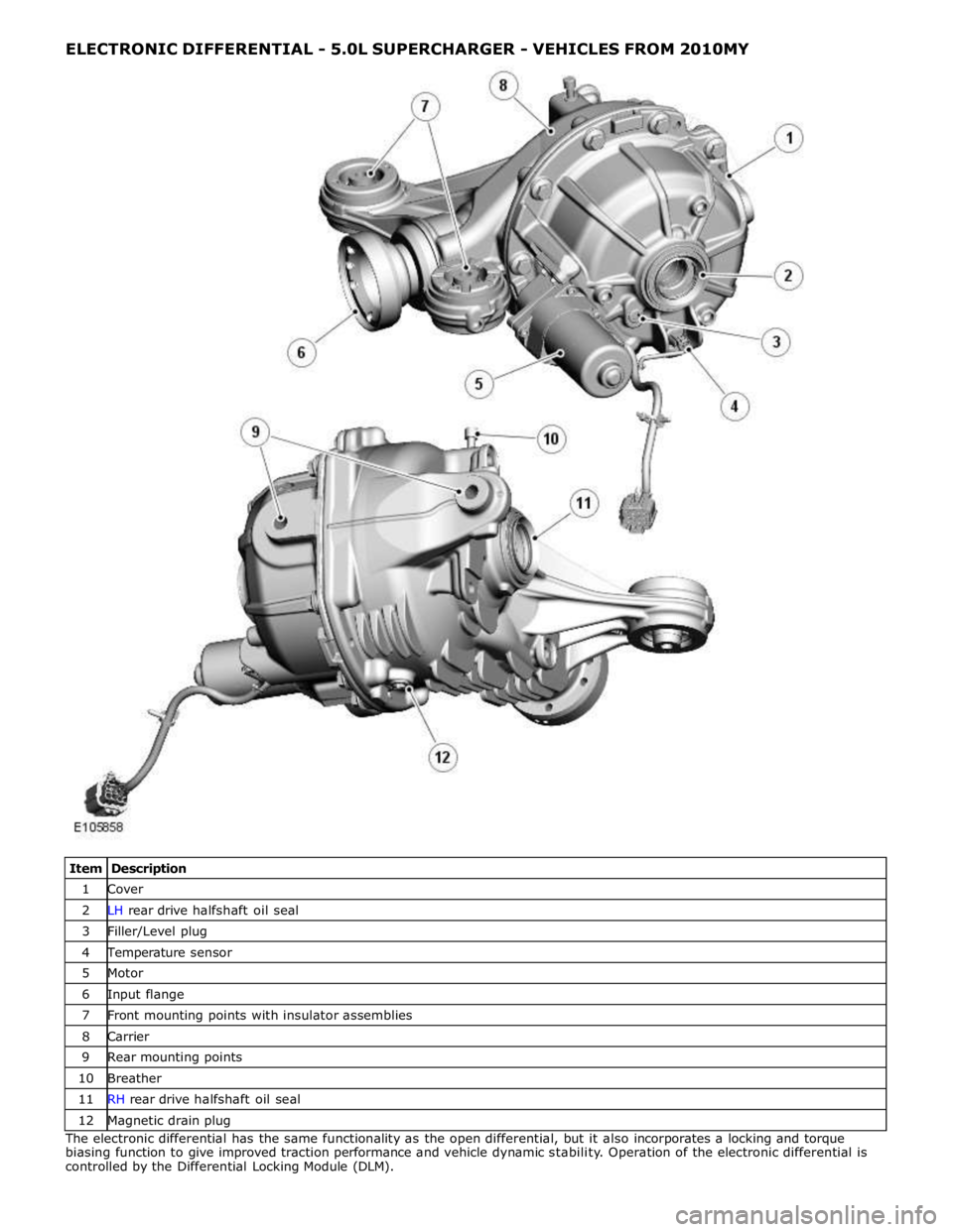
ELECTRONIC DIFFERENTIAL - 5.0L SUPERCHARGER - VEHICLES FROM 2010MY
Item Description 1 Cover 2 LH rear drive halfshaft oil seal 3 Filler/Level plug 4 Temperature sensor 5 Motor 6 Input flange 7 Front mounting points with insulator assemblies 8 Carrier 9 Rear mounting points 10 Breather 11 RH rear drive halfshaft oil seal 12 Magnetic drain plug The electronic differential has the same functionality as the open differential, but it also incorporates a locking and torque
biasing function to give improved traction performance and vehicle dynamic stability. Operation of the electronic differential is
controlled by the Differential Locking Module (DLM).
Page 535 of 3039
Thrust race 7 Shim 8 Thrust plate 9 Dished washer 10 Bolt (10 off) 11 Clutch basket 12 Multi-plate clutch and pressure disc 13 Differential case 14 Screw (2 off) 15 Bearing assembly 16 Oil seal 17 Oil slinger inner 18 Oil slinger outer 19 Input flange 20 Pinion nut 21 Collapsible spacer 22 Shim 23 Bearing assembly 24 Pinion shaft 25 Mounting insulator inner (2 off) 26 Mounting insulator rubber (2 off) 27 Mounting insulator outer (2 off) 28 Carrier 29 Oil seal 30 Drain plug 31 Vent 32 Breather cap 33 Shim 34 Bearing assembly 35 Drive gear 36 Shim 37 RH sun gear 38 Circlip 39 Thrust washer (4 off) 40 Planet gear (4 off) 41 Pin (2 off) 42 Shaft 43 LH sun gear 44 Shim 45 Bearing assembly 46 Shim 47 Dowel (2 off) 48 Bolt (4 off) 49 Reduction gear casing 50 Reduction gear 51 Shaft 52 Temperature sensor 53 O-ring seal 54 Motor 55 Screw (4 off) 56 Cover 57 Output actuator locking pin 58 Bolt (9 off)
Page 536 of 3039
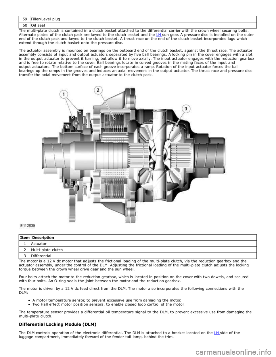
60 Oil seal The multi-plate clutch is contained in a clutch basket attached to the differential carrier with the crown wheel securing bolts.
Alternate plates of the clutch pack are keyed to the clutch basket and the LH sun gear. A pressure disc is installed on the outer end of the clutch pack and keyed to the clutch basket. A thrust race on the end of the clutch basket incorporates lugs which
extend through the clutch basket onto the pressure disc.
The actuator assembly is mounted on bearings on the outboard end of the clutch basket, against the thrust race. The actuator
assembly consists of input and output actuators separated by five ball bearings. A locking pin in the cover engages with a slot
in the output actuator to prevent it turning, but allow it to move axially. The input actuator engages with the reduction gearbox
and is free to rotate relative to the cover. Ball bearings locate in curved grooves in the mating faces of the input and
output actuators. The bottom surface of each groove incorporates a ramp. Rotation of the input actuator forces the ball
bearings up the ramps in the grooves and induces an axial movement in the output actuator. The thrust race and pressure disc
transfer the axial movement from the output actuator to the clutch pack.
Item Description 1 Actuator 2 Multi-plate clutch 3 Differential The motor is a 12 V dc motor that adjusts the frictional loading of the multi-plate clutch, via the reduction gearbox and the
actuator assembly, under the control of the DLM. Adjusting the frictional loading of the multi-plate clutch adjusts the locking
torque between the crown wheel drive gear and the sun wheel.
Four bolts attach the motor to the reduction gearbox, which is located in position on the cover with two dowels, and secured
with four bolts. An O-ring seals the joint between the motor and the reduction gearbox.
The motor is driven by a 12 V dc feed direct from the DLM. The motor also incorporates the following connections with the
DLM:
A motor temperature sensor, to prevent excessive use from damaging the motor.
Two Hall effect motor position sensors, to enable closed loop control of the motor.
The temperature sensor provides a differential oil temperature signal to the DLM, to prevent excessive use from damaging the
multi-plate clutch.
Differential Locking Module (DLM)
The DLM controls operation of the electronic differential. The DLM is attached to a bracket located on the LH side of the luggage compartment, immediately forward of the fender tail lamp, behind the trim.
Page 813 of 3039
Component Tests
Engine Oil Leaks
NOTE: Before installing new gaskets or oil seals, make sure that the fault is clearly established.
If the oil leak cannot be identified clearly by a visual inspection, carry out an Ultraviolet test:
Fluorescent Oil Additive Method
1. Clean the engine with a suitable cleaning fluid (brake cleaner).
2. Drain the engine oil and refill with recommended oil, premixed with Diesel Engine Oil Dye or equivalent. Use a minimum
14.8 ml (0.5 ounce) to a maximum 29.6 ml (1 ounce) of fluorescent additive to all engines. If oil is not premixed,
fluorescent additive must first be added to the crankcase.
3. Run engine for 15 minutes. Stop the engine and inspect all seal and gasket areas for leaks using a 12 Volt Master UV
Diagnostic Inspection Kit or equivalent. A clear bright yellow or orange area will identify leak. For extremely small
leaks, several hours may be required for the leak to appear.
4. As necessary, pressurize the main oil gallery system to locate leaks due to incorrectly sealed, loose or cocked plugs. If
the flywheel bolts leak oil, look for sealer on the threads.
5. Repair all leaks as necessary.
Compression Test General Remarks
NOTES:
Removing fuses and disconnecting electrical components may cause the Engine Control Module (ECM) to log Diagnostic
Trouble Codes (DTCs). After the measurements have been carried out, DTCs should be cleared from memory by connecting to
the Manufacturer Approved Diagnostic System.
Only check the compression pressure with the valves set to the prescribed clearance (if this can be adjusted).
The compression pressure should be checked with the engine at normal operating temperature.
Check the Compression Pressure
WARNING: Move gear selector lever to 'P' position. Failure to follow this instruction may result in personal injury.
1. Remove the fuel pump relay.
2. Start the engine - the engine will start, run for a few seconds then stall.
3. Remove the spark plugs.
4. Install the compression tester.
5. Install an auxiliary starter switch in the starting circuit. With the ignition switch OFF, using the auxiliary starter switch,
crank the engine a minimum of five compression strokes and record the highest reading. Note the approximate number
of compression strokes required to obtain the highest reading.
6. Repeat the test on each cylinder, cranking the engine approximately the same number of compression strokes.
7. Install the removed components in reverse order, observing the specified tightening torques.
8. Clear all DTCs from the ECM.
Interpretation of the Results
NOTE: Due to the possibility of loose carbon that has become trapped between the valve face and seat effecting the
pressure readings, when carrying out a compression test and cylinders are found to have low pressures, install the spark plugs,
road test the vehicle and re-test the suspect cylinders. If the correct pressures are restored, no further action is required.
The indicated compression pressures are considered within specification if the lowest reading cylinder is within 75% of the
highest reading.
If the cylinder pressures are found to be low, carry out a leakdown test to determine the location of the fault (if any leakback
can be heard through the engine breather system suspect the piston rings, if any leakback can be heard through the inlet
system suspect the inlet valve or seat, if any leakback can be heard through the exhaust manifold suspect the exhaust valve
or seat. If the measurements for two cylinders next to each other are both too low then it is very likely that the cylinder head
gasket between them is burnt through. This can also be recognized by traces of engine oil in the coolant and/or coolant in the
Page 814 of 3039
engine oil).
Oil Consumption Test
The amount of oil an engine uses will vary with the way the vehicle is driven in addition to normal engine-to-engine variation.
This is especially true during the first 16,100 km (10,000 miles) when a new engine is being broken in or until certain internal
components become conditioned. Vehicles used in heavy-duty operation may use more oil. The following are examples of
heavy-duty operation:
Trailer towing applications
Severe loading applications
Sustained high speed operation
Engines need oil to lubricate the following internal components:
Cylinder block cylinder walls
Pistons and piston rings
Intake and exhaust valve stems
Intake and exhaust valve guides
All internal engine components
When the pistons move downward, a thin film of oil is left on the cylinder walls. As the vehicle is operated, some oil is also
drawn into the combustion chambers past the intake and exhaust valve stem seals and burned.
The following are examples of conditions that can affect oil consumption rates:
Engine size
Operator driving habits
Ambient temperatures
Quality and viscosity of oil
Engine is being run in an overfilled condition (check the oil level at least five minutes after a hot shutdown with the
vehicle parked on a level surface. The oil level should not be above the top of the cross-hatched area and the letter "F"
in FULL).
Operation under varying conditions can frequently be misleading. A vehicle that has been run for several thousand miles on
short trips or in below-freezing ambient temperatures may have consumed a "normal" amount of oil. However, when checking
the engine oil level, it may measure up to the full mark on the oil level indicator due to dilution (condensation and fuel) in the
engine crankcase. The vehicle then might be driven at high speeds on the highway where the condensation and fuel boil off.
The next time the engine oil is checked it may appear that a liter of oil was used in about 160 km (100 miles). Oil
consumption rate is about one liter per 2,400 km (1,500 miles).
Make sure the selected engine oil meets Jaguar specification and the recommended API performance category "SG" and SAE
viscosity grade as shown in the vehicle Owner's Guide. It is also important that the engine oil is changed at the intervals
specified for the typical operating conditions.
The following diagnostic procedure is used to determine the source of excessive oil consumption.
NOTE: Oil use is normally greater during the first 16,100 km (10,000 miles) of service. As mileage increases, oil use
decreases. High speed driving, towing, high ambient temperature and other factors may result in greater oil use.
1. Define excessive consumption, such as the number of miles driven per liter of oil used. Also determine customers
driving habits, such as sustained high speed operation, towing, extended idle and other considerations.
2. Verify that the engine has no external oil leaks as described under Engine Oil Leaks in this section.
3. Carry out an oil consumption test:
Run the engine to normal operating temperature. Switch engine OFF and allow oil to drain back for at least five
minutes .
With vehicle parked on level surface, check the engine oil level.
If required, add engine oil to set level exactly to the FULL mark.
Record the vehicle mileage.
Instruct the customer to return for a level check after driving the vehicle as usual for 1,610 km (1000 miles).
Check the oil level under the same conditions and at the same location as the initial check.
NOTE: If the oil consumption rate is unacceptable go to Step 4.
4. Check the Positive Crankcase Ventilation (PCV) system. Make sure the system is not plugged.
5. Check for plugged oil drain-back holes in the cylinder head and cylinder block.
6. If the condition still exists after carrying out the above tests go to step 9.
7. Carry out a cylinder compression test. Refer to the Compression Test procedure in this section. This can help determine
the source of oil consumption such as valves, piston rings or other areas.
8. Check valve guides for excessive guide clearance. Install new valve stem seals after verifying valve guide clearance.
9. Worn or damaged internal engine components can cause excessive oil consumption. Small deposits of oil on the tips of
the spark plugs can be a clue to internal oil consumption.
Page 816 of 3039
9. WEAK VALVE SPRINGS: When the needle oscillation becomes more violent as engine RPM is increased, weak valve
springs are indicated. The reading at idle could be relatively steady.
10. LATE VALVE TIMING: A steady but low reading could be caused by late valve timing.
11.
IGNITION TIMING RETARDED: Retarded ignition timing will produce a steady but somewhat low reading.
12.
INSUFFICIENT SPARK PLUG GAP: When spark plugs are gapped too close, a regular, small pulsation of the needle can
occur.
13. INTAKE LEAK: A low, steady reading can be caused by an intake manifold or throttle body gasket leak.
14.
BLOWN HEAD GASKET: A regular drop of fair magnitude can be caused by a blown head gasket or warped cylinder head
to cylinder block surface.
15.
RESTRICTED EXHAUST SYSTEM: When the engine is first started and is idled, the reading may be normal, but as the
engine RPM is increased, the back pressure caused by a clogged muffler, kinked tail pipe or other concerns will cause
the needle to slowly drop to 0 kPa (0 in-Hg). The needle then may slowly rise. Excessive exhaust clogging will cause
the needle to drop to a low point even if the engine is only idling.
When vacuum leaks are indicated, search out and correct the cause. Excess air leaking into the system will upset the fuel
mixture and cause concerns such as rough idle, missing on acceleration or burned valves. If the leak exists in an accessory
such as the power brake booster, the unit will not function correctly. Always repair vacuum leaks.
Engine Oil Pressure Check
NOTE: Prior to checking the engine oil pressure, a road test of 6 miles (10 kilometres), must be carried out. Do not
attempt to attain engine normal operating temperature by allowing the engine to idle.
1. Disconnect the battery ground cable. Refer to section 414-00 - Charging System - General Information of the workshop
manual
2. WARNINGS:
The spilling of hot engine oil is unavoidable during this procedure, care must be taken to prevent scalding.
Wear protective gloves.
Remove the engine oil filter element
REFER to: Oil Filter Element (303-01C Engine - V8 5.0L Petrol, Removal and Installation).
NOTE: Ensure the oil filter element is not contaminated during this procedure
3. Install the oil filter element into special tool (Oil filter adapter number 303-1451)
4. Install the special tool (Oil filter adapter number 303-1451) to the engine. Torque: 25 Nm
5. Install the special tool (Oil pressure testing gauge, 303-871) and tighten the union
6. Connect the battery ground cable
7. Refer to owner hand book, check and top-up the engine oil if required
8. Start and run the engine
9. Note the oil pressure readings with the engine running at idle and 3500 RPM
10.
Turn off the engine
11.
Disconnect the battery ground cable
12. Remove the special tools
1. Clean the components
13.
Install the engine oil filter element
REFER to: Oil Filter Element (303-01C Engine - V8 5.0L Petrol, Removal and Installation).
NOTE: Ensure the oil filter element is not contaminated during this procedure
14.
Connect the battery ground cable
15. Refer to owner hand book, check and top-up the engine oil if required
www.JagDocs.com
Page 845 of 3039

Item Specification Camshaft journal maximum run out limit (mm) Camshaft journals to end journals 0.03 Camshaft journals to adjacent journals 0.015 Camshaft journal maximum out of round (mm) - all journals 0.005 Torque Specification
NOTE: A = Refer to procedure for correct torque sequence.
Description Nm lb-ft lb-in Engine cover mounting bolts 10 7 - Accessory drive belt tensioner retaining bolt 40 30 - Supercharger belt idler/tensioner bracket retaining bolts 25 18 - Secondary drive belt idler retaining bolts 40 30 - Power steering pump pulley retaining bolts 25 18 - Power steering pump retaining bolts 25 18 - Power steering pump bracket to engine retaining bolts 25 18 - Generator retaining bolts 48 35 - Starter motor retaining bolts 48 35 - Air conditioning compressor retaining bolts 25 18 - Engine mounting to engine mounting bracket retaining nuts 48 35 - Engine mounting to subframe retaining nuts 63 46 - Engine mounting bracket to engine retaining bolts 48 35 - Crankshaft damper pulley retaining LH threaded bolt 200 + 270° 148 + 180° - Flexplate retaining bolts 45 + 90° 33 + 90° - Exhaust manifold heat shield retaining bolts A - - Exhaust manifold retaining bolts A - - Engine wiring harness bracket retaining bolts 10 7 - Coolant outlet pipe 10 7 - Intercooler retaining bolts 25 18 - Intake manifold retaining bolts 25 18 - Oil Cooler retaining bolts 13 10 - Knock sensor (KS) retaining bolt 20 14 - Ignition coil retaining bolts 8 - 71 Spark plugs 20 15 - Fuel rail retaining bolts A - - High pressure fuel pipe retaining bolts A - - High pressure fuel pump retaining bolts 12 9 - Oil filter housing assembly retaining bolts 12 9 - Oil filter cap 28 21 - Lifting eye bolts 25 + 90° 18 + 90° - Manifold absolute pressure and temperature (MAPT) sensor sensor retaining bolts 5 - 44 Coolant pump retaining bolts 12 9 - Variable valve timing (VVT) oil control solenoid retaining bolts 10 7 - Camshaft position (CMP) sensor retaining bolts 10 7 - Camshaft cover retaining bolts 13 10 - Front upper timing cover retaining bolts 12 9 - Front lower timing cover retaining bolts A - - Engine rear cover retaining bolts A - - VVT to camshaft retaining bolts 32 24 - Camshaft bearing caps retaining bolts 11 8 - Primary timing chain fixed guide retaining bolts 12 9 - Primary timing chain tensioner retaining bolts 12 9 - Primary timing chain tensioner guide blade retaining bolts 25 18 - Auxiliary chain tensioner guide retaining bolts 21 15 - Auxiliary chain fixed guide retaining bolt 12 9 - Oil pump sprocket retaining bolt 21 15 - Cylinder head retaining bolts A - - Engine oil level (EOL) sensor retaining bolt 12 9 - Oil pan to oil sump body retaining bolts 12 9 - Oil sump body to engine retaining bolts 25 18 - Oil pan drain plug 23 17 - Oil transfer tube to Oil pan body retaining bolts 11 8 - Oil pump to engine block retaining bolts 25 18 - Pick-up pipe to oil pump retaining bolts 12 9 - Windage tray retaining bolts 25 18 - Piston cooling jet retaining bolts 12 9 - Engine block coolant draining plug 50 37 - Connecting Rod bolts Stage 1 10 7 - Stage 2 50 37 -
Page 867 of 3039
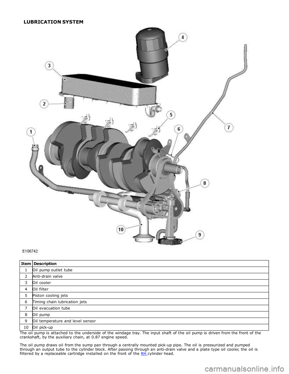
1 Oil pump outlet tube 2 Anti-drain valve 3 Oil cooler 4 Oil filter 5 Piston cooling jets 6 Timing chain lubrication jets 7 Oil evacuation tube 8 Oil pump 9 Oil temperature and level sensor 10 Oil pick-up The oil pump is attached to the underside of the windage tray. The input shaft of the oil pump is driven from the front of the
crankshaft, by the auxiliary chain, at 0.87 engine speed.
The oil pump draws oil from the sump pan through a centrally mounted pick-up pipe. The oil is pressurized and pumped
through an output tube to the cylinder block. After passing through an anti-drain valve and a plate type oil cooler, the oil is
filtered by a replaceable cartridge installed on the front of the RH cylinder head. LUBRICATION SYSTEM
Page 868 of 3039
cooling jets and the timing chain lubrication jets.
The oil returns to the oil pan under gravity. Large drain holes through the cylinder heads and cylinder block ensure the rapid
return of the oil to the sump pan. System replenishment is through the oil filler cap on the LH cylinder head cover.
An oil evacuation tube is installed to allow oil to be drawn from the sump pan. The upper end of the oil evacuation tube is
located under the oil filler cap.
An oil drain plug is installed in the RH side of the sump pan.
Oil Pump Nominal Operating Pressures
Engine Speed, rev/min Temperature, °C (°F) Pressure, bar (lbf/in2
) Idle 20 (68) 2.0 (29.0) 1500 20 (68) 6.0 (87.0) 3000 40 (104) 6.2 (90.0) 3000 110 (230) 5.0 (72.5) 3000 130 (266) 4.0 (58.0) Oil Level Monitoring
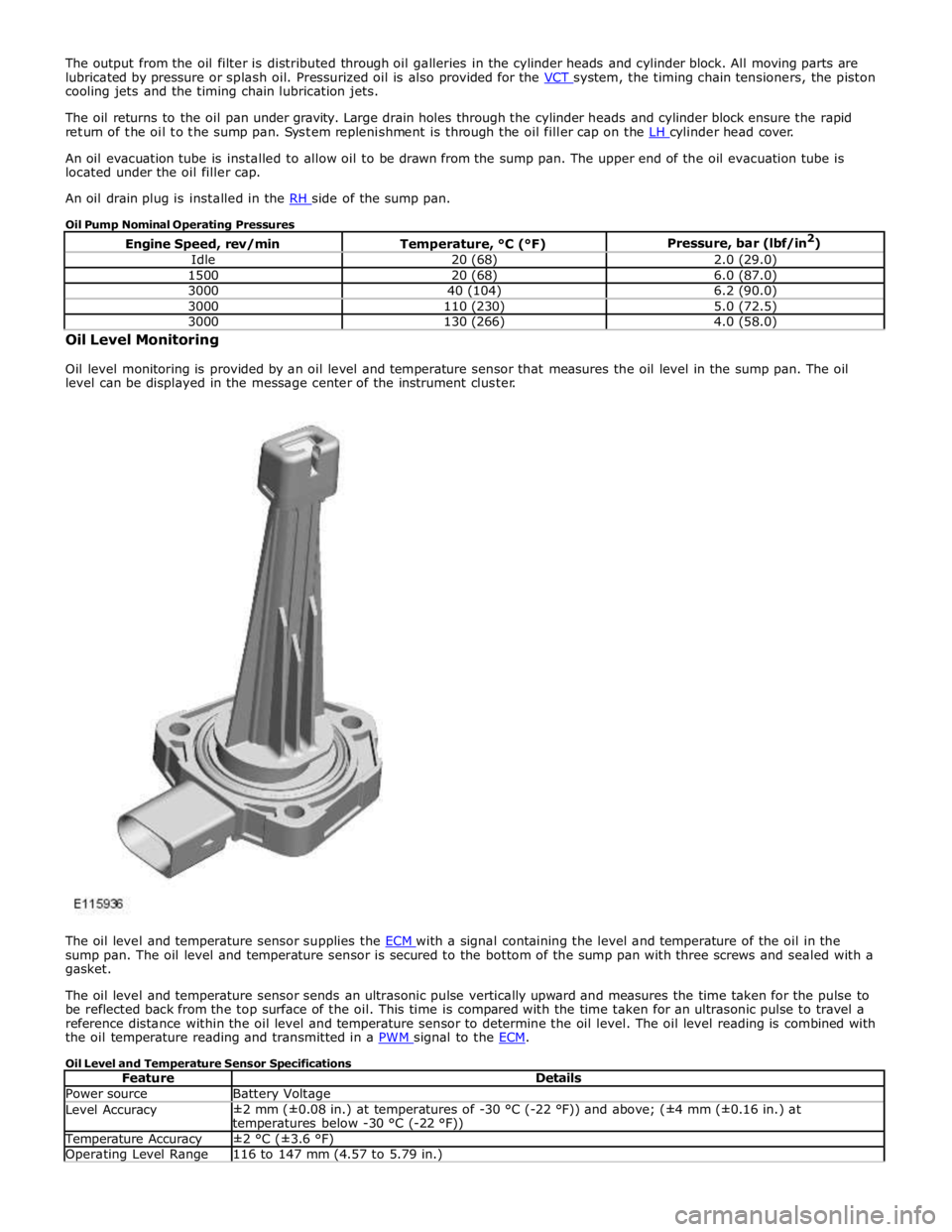
Oil level monitoring is provided by an oil level and temperature sensor that measures the oil level in the sump pan. The oil
level can be displayed in the message center of the instrument cluster.
The oil level and temperature sensor supplies the ECM with a signal containing the level and temperature of the oil in the sump pan. The oil level and temperature sensor is secured to the bottom of the sump pan with three screws and sealed with a
gasket.
The oil level and temperature sensor sends an ultrasonic pulse vertically upward and measures the time taken for the pulse to
be reflected back from the top surface of the oil. This time is compared with the time taken for an ultrasonic pulse to travel a
reference distance within the oil level and temperature sensor to determine the oil level. The oil level reading is combined with
the oil temperature reading and transmitted in a PWM signal to the ECM.
Oil Level and Temperature Sensor Specifications
Feature Details Power source Battery Voltage Level Accuracy ±2 mm (±0.08 in.) at temperatures of -30 °C (-22 °F)) and above; (±4 mm (±0.16 in.) at
temperatures below -30 °C (-22 °F)) Temperature Accuracy ±2 °C (±3.6 °F) Operating Level Range 116 to 147 mm (4.57 to 5.79 in.)