tilt JAGUAR XFR 2010 1.G Owner's Manual
[x] Cancel search | Manufacturer: JAGUAR, Model Year: 2010, Model line: XFR, Model: JAGUAR XFR 2010 1.GPages: 3039, PDF Size: 58.49 MB
Page 2335 of 3039

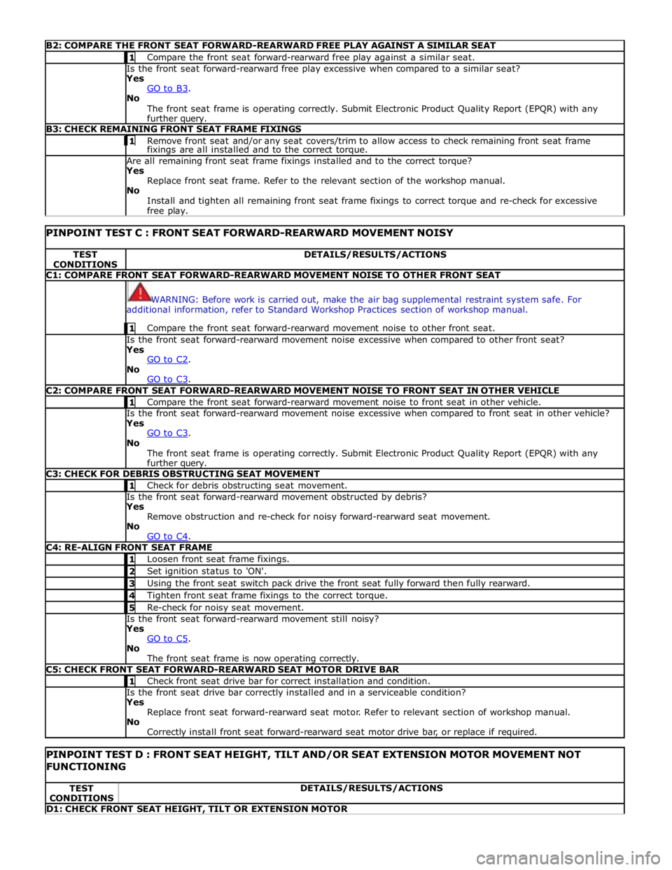
B2: COMPARE THE FRONT SEAT FORWARD-REARWARD FREE PLAY AGAINST A SIMILAR SEAT 1 Compare the front seat forward-rearward free play against a similar seat. Is the front seat forward-rearward free play excessive when compared to a similar seat?
Yes
GO to B3. No
The front seat frame is operating correctly. Submit Electronic Product Quality Report (EPQR) with any
further query. B3: CHECK REMAINING FRONT SEAT FRAME FIXINGS 1 Remove front seat and/or any seat covers/trim to allow access to check remaining front seat frame fixings are all installed and to the correct torque. Are all remaining front seat frame fixings installed and to the correct torque?
Yes
Replace front seat frame. Refer to the relevant section of the workshop manual.
No
Install and tighten all remaining front seat frame fixings to correct torque and re-check for excessive
free play.
PINPOINT TEST C : FRONT SEAT FORWARD-REARWARD MOVEMENT NOISY TEST
CONDITIONS DETAILS/RESULTS/ACTIONS C1: COMPARE FRONT SEAT FORWARD-REARWARD MOVEMENT NOISE TO OTHER FRONT SEAT
WARNING: Before work is carried out, make the air bag supplemental restraint system safe. For
additional information, refer to Standard Workshop Practices section of workshop manual. 1 Compare the front seat forward-rearward movement noise to other front seat. Is the front seat forward-rearward movement noise excessive when compared to other front seat?
Yes
GO to C2. No
GO to C3. C2: COMPARE FRONT SEAT FORWARD-REARWARD MOVEMENT NOISE TO FRONT SEAT IN OTHER VEHICLE 1 Compare the front seat forward-rearward movement noise to front seat in other vehicle. Is the front seat forward-rearward movement noise excessive when compared to front seat in other vehicle?
Yes
GO to C3. No
The front seat frame is operating correctly. Submit Electronic Product Quality Report (EPQR) with any
further query. C3: CHECK FOR DEBRIS OBSTRUCTING SEAT MOVEMENT 1 Check for debris obstructing seat movement. Is the front seat forward-rearward movement obstructed by debris?
Yes
Remove obstruction and re-check for noisy forward-rearward seat movement.
No
GO to C4. C4: RE-ALIGN FRONT SEAT FRAME 1 Loosen front seat frame fixings. 2 Set ignition status to 'ON'. 3 Using the front seat switch pack drive the front seat fully forward then fully rearward. 4 Tighten front seat frame fixings to the correct torque. 5 Re-check for noisy seat movement. Is the front seat forward-rearward movement still noisy?
Yes
GO to C5. No
The front seat frame is now operating correctly. C5: CHECK FRONT SEAT FORWARD-REARWARD SEAT MOTOR DRIVE BAR 1 Check front seat drive bar for correct installation and condition. Is the front seat drive bar correctly installed and in a serviceable condition?
Yes
Replace front seat forward-rearward seat motor. Refer to relevant section of workshop manual.
No
Correctly install front seat forward-rearward seat motor drive bar, or replace if required.
PINPOINT TEST D : FRONT SEAT HEIGHT, TILT AND/OR SEAT EXTENSION MOTOR MOVEMENT NOT FUNCTIONING TEST
CONDITIONS DETAILS/RESULTS/ACTIONS D1: CHECK FRONT SEAT HEIGHT, TILT OR EXTENSION MOTOR
Page 2336 of 3039

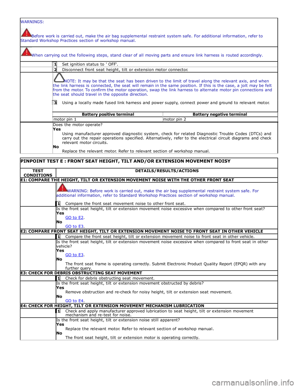
WARNINGS:
Before work is carried out, make the air bag supplemental restraint system safe. For additional information, refer to
Standard Workshop Practices section of workshop manual.
When carrying out the following steps, stand clear of all moving parts and ensure link harness is routed accordingly. 1 Set ignition status to ' OFF'. 2 Disconnect front seat height, tilt or extension motor connector.
NOTE: It may be that the seat has been driven to the limit of travel along the relevant axis, and when
the link harness is connected, the seat will remain in the same position. If this is the case, a jolt may be felt
from the motor. To confirm the motor operation, swap the link harness to alternate motor pin connections and
the seat should travel in the opposite direction. 3 Using a locally made fused link harness and power supply, connect power and ground to relevant motor. Battery positive terminal Battery negative terminal motor pin 1 motor pin 2 Does the motor operate? Yes
Using manufacturer approved diagnostic system, check for related Diagnostic Trouble Codes (DTCs) and
carry out the repair operations specified. Alternatively, refer to the electrical circuit diagrams and check
relevant motor circuits.
No
Replace the relevant motor. Refer to relevant section of workshop manual.
PINPOINT TEST E : FRONT SEAT HEIGHT, TILT AND/OR EXTENSION MOVEMENT NOISY TEST
CONDITIONS DETAILS/RESULTS/ACTIONS E1: COMPARE THE HEIGHT, TILT OR EXTENSION MOVEMENT NOISE WITH THE OTHER FRONT SEAT
WARNING: Before work is carried out, make the air bag supplemental restraint system safe. For
additional information, refer to Standard Workshop Practices section of workshop manual. 1 Compare the front seat movement noise to other front seat. Is the front seat height, tilt or extension movement noise excessive when compared to other front seat?
Yes
GO to E2. No
GO to E3. E2: COMPARE FRONT SEAT HEIGHT, TILT OR EXTENSION MOVEMENT NOISE TO FRONT SEAT IN OTHER VEHICLE 1 Compare the front seat height, tilt or extension movement noise to front seat in other vehicle. Is the front seat height, tilt or extension movement noise excessive when compared to front seat in other
vehicle?
Yes
GO to E3. No
The front seat frame is operating correctly. Submit Electronic Product Quality Report (EPQR) with any
further query. E3: CHECK FOR DEBRIS OBSTRUCTING SEAT MOVEMENT 1 Check for debris obstructing seat movement. Is the front seat height, tilt or extension movement obstructed by debris?
Yes
Remove obstruction and re-check for noisy height, tilt or extension seat movement.
No
GO to E4. E4: CHECK FOR HEIGHT, TILT OR EXTENSION MOVEMENT MECHANISM LUBRICATION 1 Check and apply manufacturer approved lubrication to seat height, tilt or extension movement mechanism and re-test for noise. Is the front seat height, tilt or extension noise still apparent?
Yes
Replace the relevant motor. Refer to relevant section of workshop manual.
No
The front seat height, tilt or extension motor is operating correctly.
Page 2358 of 3039

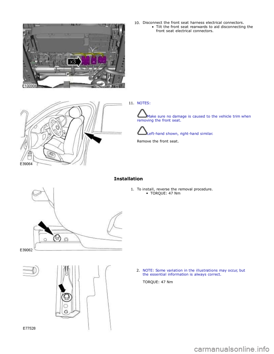
10. Disconnect the front seat harness electrical connectors.
Tilt the front seat rearwards to aid disconnecting the
front seat electrical connectors.
11. NOTES:
Make sure no damage is caused to the vehicle trim when
removing the front seat.
Left-hand shown, right-hand similar.
Remove the front seat.
Installation
1. To install, reverse the removal procedure.
TORQUE: 47 Nm
2. NOTE: Some variation in the illustrations may occur, but
the essential information is always correct.
TORQUE: 47 Nm
Page 2562 of 3039

Roof opening panel System Operation
Operation of the roof opening panel is controlled by the roof opening panel control module, which is integral with the motor.
The control module receives inputs from the CJB, which provides an 'open' or 'close' signal for remote handset operation, and
an 'enable' signal when the vehicle enters power mode 6.
The control module also receives a vehicle speed signal from the ABS module. The vehicle speed signal is used by the control
module to calibrate the anti-trap feature.
If the battery is disconnected, or the power supply is interrupted while the roof opening panel is in a partially open position,
the motor and control module will need to be calibrated to restore full functionality. To recalibrate:
1. Switch ignition on.
2. Press the front of the switch, so the roof opening panel is the tilt position, and then release the switch.
3. Press the front of the switch and hold for thirty seconds.
4. After thirty seconds the roof opening panel will begin to move. Keep the front of the switch pressed until the roof
opening panel has fully opened and then closed.
5. Once the open/close cycle has completed and the roof opening panel has stopped moving, release the switch.
6. The roof opening panel can now be operated as normal.
Drain hoses are connected to the front and rear corners of the roof opening panel frame. The drain hoses are located inside of
the cabin on the 'A' and 'D' post pillars to allow water, which has collected in the frame, to escape. One-way valves fitted to
the end of each drain hose, prevent the ingress of dirt and moisture.
Rear window sunblind
The powered rear window sunblind is operated through a switch in the roof console. Power to the sunblind motor is provided by
a pair of relays located in the CJB when the vehicle enters power mode 4. The sunblind motor is located beneath the rear parcel
shelf and is supplied as a sealed unit with the sunblind mechanism.
If the battery is disconnected or a replacement sunblind is fitted, the motor will require re-calibrating. To re-calibrate the
motor the sunblind should be powered through two-full cycles of movement.
Roof opening panel, motor Component Description
The roof opening panel motor has a worm drive which drives a gear in the cast housing attached to the end of the motor. The
gear has a small pinion gear attached to the outer part of its spindle. The pinion engages with two cables to form a rack and
pinion drive. Rotation of the motor turns the pinion which in turn drives the cables in the required direction.
The two cables are attached either side of the pinion. One end of each cable is attached to the guide; the opposite end of
each cable is held in position on the pinion by a metal insert in the frame. The cables run in channels, in the panel frame to
the guides. As the panel is closed the cables are pushed through channels in the front of the frame. The displaced cable is
guided into a further two channels in the frame, which protect the cable and prevent it from snagging. The cables
manufactured from rigid spring steel can pull as well as push the panel along the guides.
The motor contains a micro-switch and Hall effect sensor. Signals received from these components enable the control module
to calculate the exact position of the roof opening panel. The Hall effect sensor is also responsible for the operation of the
anti-trap function.
If the anti-trap feature is activated while the roof opening panel is closing, the panel is reversed for 200mm or as far as
possible. The Hall effect sensor, located in the motor, monitors the speed of the motor and if the speed decreases below a set
threshold, indicating an obstruction, the power feed to the motor is reversed so the panel goes back. In an emergency the
anti-trap function can be overridden by holding the switch in the closed position.
Roof opening panel, control module
The roof opening panel control module is integrated within the motor. The control module receives inputs from the CJB, which
provides an 'open' or 'close' signal for remote handset operation, and an 'enable' signal when the vehicle enters power mode 6.
The control module also contains the algorithm for the anti-trap system and receives a vehicle speed signal from the ABS
module. The vehicle speed signal is used by the control module to calibrate the anti-trap feature.
Page 2567 of 3039

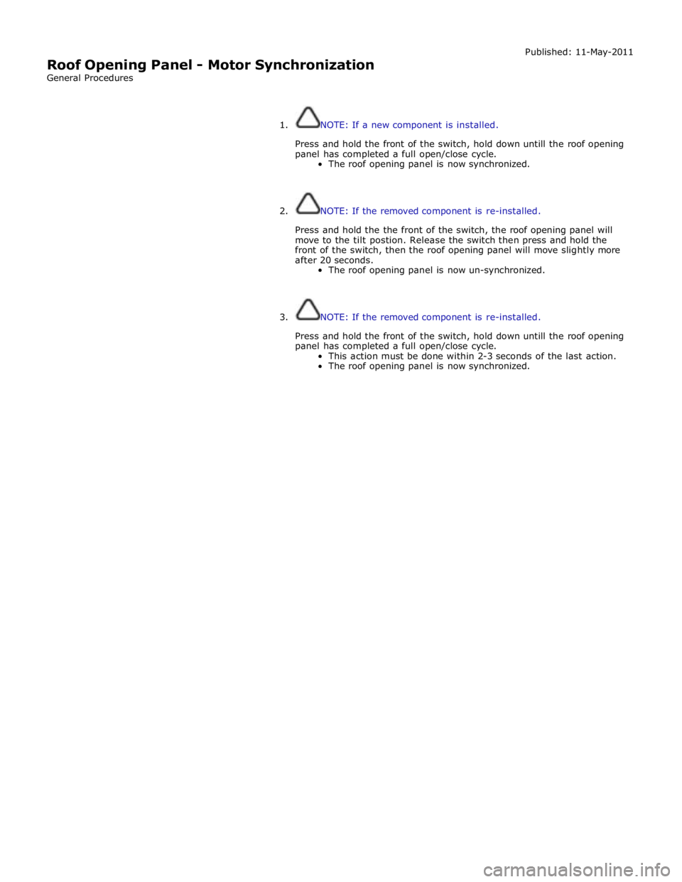
Roof Opening Panel - Motor Synchronization
General Procedures Published: 11-May-2011
1. NOTE: If a new component is installed.
Press and hold the front of the switch, hold down untill the roof opening
panel has completed a full open/close cycle.
The roof opening panel is now synchronized.
2. NOTE: If the removed component is re-installed.
Press and hold the the front of the switch, the roof opening panel will
move to the tilt postion. Release the switch then press and hold the
front of the switch, then the roof opening panel will move slightly more
after 20 seconds.
The roof opening panel is now un-synchronized.
3. NOTE: If the removed component is re-installed.
Press and hold the front of the switch, hold down untill the roof opening
panel has completed a full open/close cycle.
This action must be done within 2-3 seconds of the last action.
The roof opening panel is now synchronized.
Page 2735 of 3039

Side windows
In the case of side windows, the same problems can arise as for a windscreen. The same corrective actions must therefore be
used.
Door seal
Diagnosis:
- Water ingress in the lower part of the interior door trim or in the rocker panel area.
Cause:
- The water shield fitted behind the interior door trim exists to drain off water that has entered the door via the
drainage holes, either downwards or outwards. If the water shield seal is damaged or has been fitted incorrectly,
then water can get into the passenger compartment.
- In addition to this, the drainage holes can become clogged with leaves, dirt or excess cavity protection agents.
Water gathers in the door and ingresses into the passenger compartment.
- Check water shield for damage or correct fitting.
- If the water shield needs to be re-bonded, then approved seam sealer should be used.
- Before the water shield is installed, the drainage holes must be checked for unhindered flow.
Door seals
Diagnosis:
- Ingress of water into the rocker panel area
Cause:
- Insufficient clamping load between seal and door.
Corrective action:
NOTE: When adjusting the clamping load, the profile alignment of the relevant components must always be taken
into consideration.
NOTE: Do not realign the flange too far in the direction of the door, as this can reduce the bearing surface of the
seal to the door.
- Check clamping load:
- The easiest way to check the clamping load of a seal to the respective bearing surface is by means of a paper
strip test. This consists of trapping strips of paper at various points between the door and the seal, and fully
closing the door. If it is possible to pull out the paper with no great resistance, then the clamping load is too
low.
- Adjust the clamping load:
- The clamping load is normally adjusted using the striker. When doing so, the edge alignment from the door to
the side panel, or from the front door to the rear door must be taken into account.
- Another setting method is to realign the panel flange for the seal mounting. The clamping load is increased by
moving the flange towards the door.
- Check the bearing surface:
- Apply chalk evenly to the surface of the seal. Evenly coat the bearing surface of the door with Vaseline.
- Close the door fully, the lock must engage. Open the door. The imprint of the chalk (bearing surface) can be
identified in the film of Vaseline.
- The bearing surface should be at least 5mm across at all points.
Other causes:
- The door seal must completely seal the door where it meets the bodywork.
- Water can ingress directly or indirectly into the interior of the vehicle if the seal is damaged at any point.
Corrective action:
- A damaged or worn door seal must always be renewed in full.
- When renewing the seal, the following must be taken into account:
- Always fit the seal first in the area of the narrow radii (corner points).
- Next, secure the seal to the flange evenly by tapping lightly with a rubber hammer. The installed seal must not
be kinked at any point.
NOTE: The prescribed length of a seal must not be shortened.
Other cause:
- The door seal is attached to the welded flange all the way round. If this welded flange is uneven or damaged at
any point (usually in areas with small radii) then this point could be subject to leaks.
- A stretched seal carrier can also cause a leak.
- In both cases, water gets into the vehicle interior under the seal carrier.
Corrective action:
- Align the deformed welded flange using a hammer and anvil block, prevent and, if necessary, repair any paint
damage.
Sliding roof/tilting roof
Diagnosis:
- Ingress of water at sliding roof aperture
Cause:
- The sliding roof/tilting roof is installed in a water trap. The water drains off via the water trap, water drain holes
and drain hoses. The drain hoses lead downwards on both sides via the A-pillar and B-pillar.
- The drain holes or drain hoses can become clogged with leaves, dirt, underbody protection and so on.
Corrective action:
Page 2736 of 3039

NOTE: In the case of a sliding or tilting roof, the external rubber seal and the lock actuator or latch mechanism
must be checked first of all.
- Check the water trap for leaks.
- Check the drain hoses for leaks and for correct connection to the water trap.
- Check the drainage system for unhindered flow, and blow out with compressed air if necessary.
- Check the external seal and the correct adjustment of the sliding roof.
Liftgate
Diagnosis:
- Ingress of water into rear headlining area and luggage area.
Cause:
- The leak problems of the tailgate and liftgate correspond to those of the doors.
- In addition to this, the area to be sealed is much bigger. The routing holes for cables and hoses must also be
sealed.
- The rubber grommets for the routing holes must be checked for damage and correct seating (fully unhooked).
- The mounting points of the liftgate hinges may leak.
Corrective action:
- Check the rubber grommets and renew if necessary.
- Check the hinge mounting points, and re-seal with sealing compound if necessary.
Forced air extraction
Diagnosis:
- Ingress of water into side luggage compartment area
Cause:
- The forced air extraction for the vehicle interior is located in the quarter panel lower extension.
- The rubber flap of the forced air extraction must be able to move freely.
Corrective action:
- Remove the forced air extraction.
- Check the seal area between the bodywork and housing, as well as the rubber flap.
- Renew seal if necessary.
Rear window
Diagnosis:
- Ingress of water into the luggage compartment area
Cause:
- Rear window leaking.
- Check for leak in the same way as for leaking windscreen.