wheel alignment JAGUAR XFR 2010 1.G Owner's Guide
[x] Cancel search | Manufacturer: JAGUAR, Model Year: 2010, Model line: XFR, Model: JAGUAR XFR 2010 1.GPages: 3039, PDF Size: 58.49 MB
Page 1644 of 3039
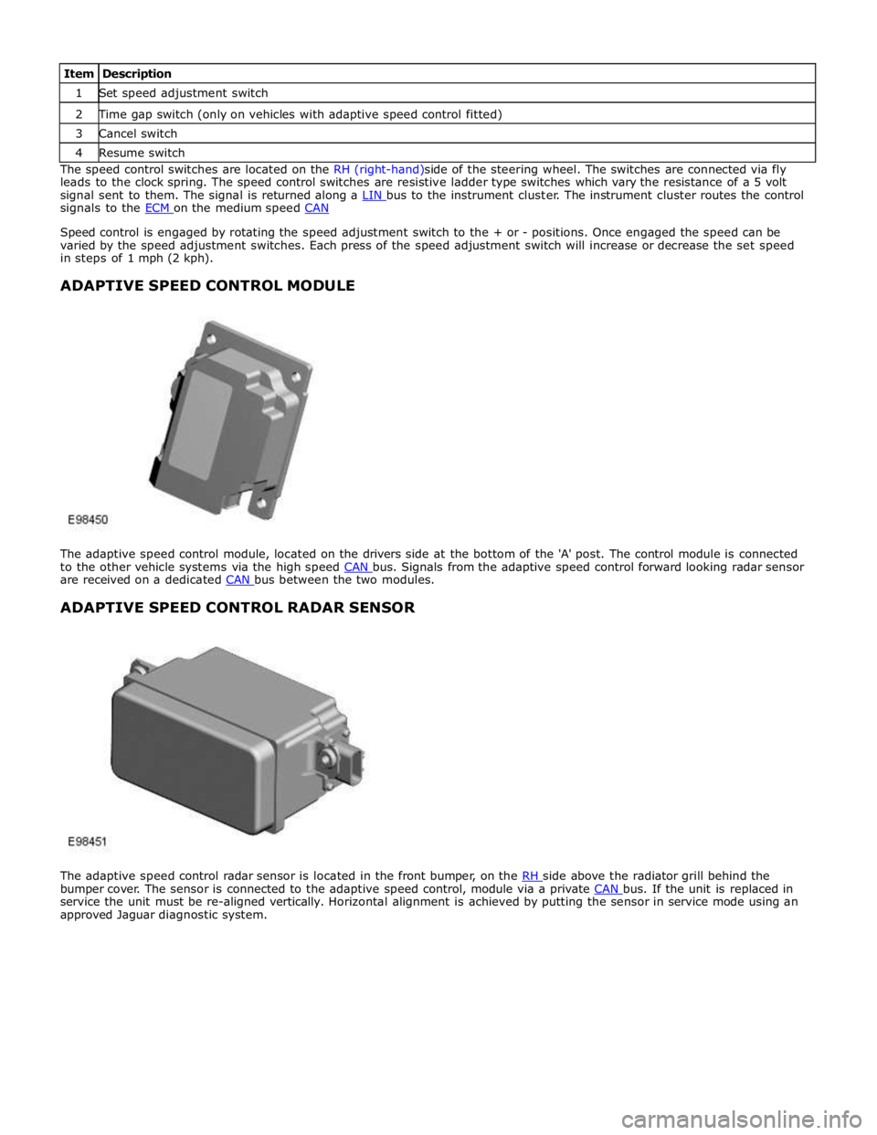
1 Set speed adjustment switch 2 Time gap switch (only on vehicles with adaptive speed control fitted) 3 Cancel switch 4 Resume switch The speed control switches are located on the RH (right-hand)side of the steering wheel. The switches are connected via fly
leads to the clock spring. The speed control switches are resistive ladder type switches which vary the resistance of a 5 volt
signal sent to them. The signal is returned along a LIN bus to the instrument cluster. The instrument cluster routes the control signals to the ECM on the medium speed CAN
Speed control is engaged by rotating the speed adjustment switch to the + or - positions. Once engaged the speed can be
varied by the speed adjustment switches. Each press of the speed adjustment switch will increase or decrease the set speed
in steps of 1 mph (2 kph).
ADAPTIVE SPEED CONTROL MODULE
The adaptive speed control module, located on the drivers side at the bottom of the 'A' post. The control module is connected
to the other vehicle systems via the high speed CAN bus. Signals from the adaptive speed control forward looking radar sensor are received on a dedicated CAN bus between the two modules.
ADAPTIVE SPEED CONTROL RADAR SENSOR
The adaptive speed control radar sensor is located in the front bumper, on the RH side above the radiator grill behind the bumper cover. The sensor is connected to the adaptive speed control, module via a private CAN bus. If the unit is replaced in service the unit must be re-aligned vertically. Horizontal alignment is achieved by putting the sensor in service mode using an
approved Jaguar diagnostic system.
Page 1646 of 3039
Published: 08-Nov-2013
Speed Control - V8 5.0L Petrol/V8 S/C 5.0L Petrol - Speed Control
Diagnosis and Testing
Principles of Operation
For a detailed description of the speed control system, refer to the relevant Description and Operation sections in the
workshop manual.
Inspection and Verification
CAUTION: Diagnosis by substitution from a donor vehicle is NOT acceptable. Substitution of control modules does not
guarantee confirmation of a fault, and may also cause additional faults in the vehicle being tested and/or the donor vehicle.
1. Verify the customer concern.
2. Visually inspect for obvious signs of damage and system integrity.
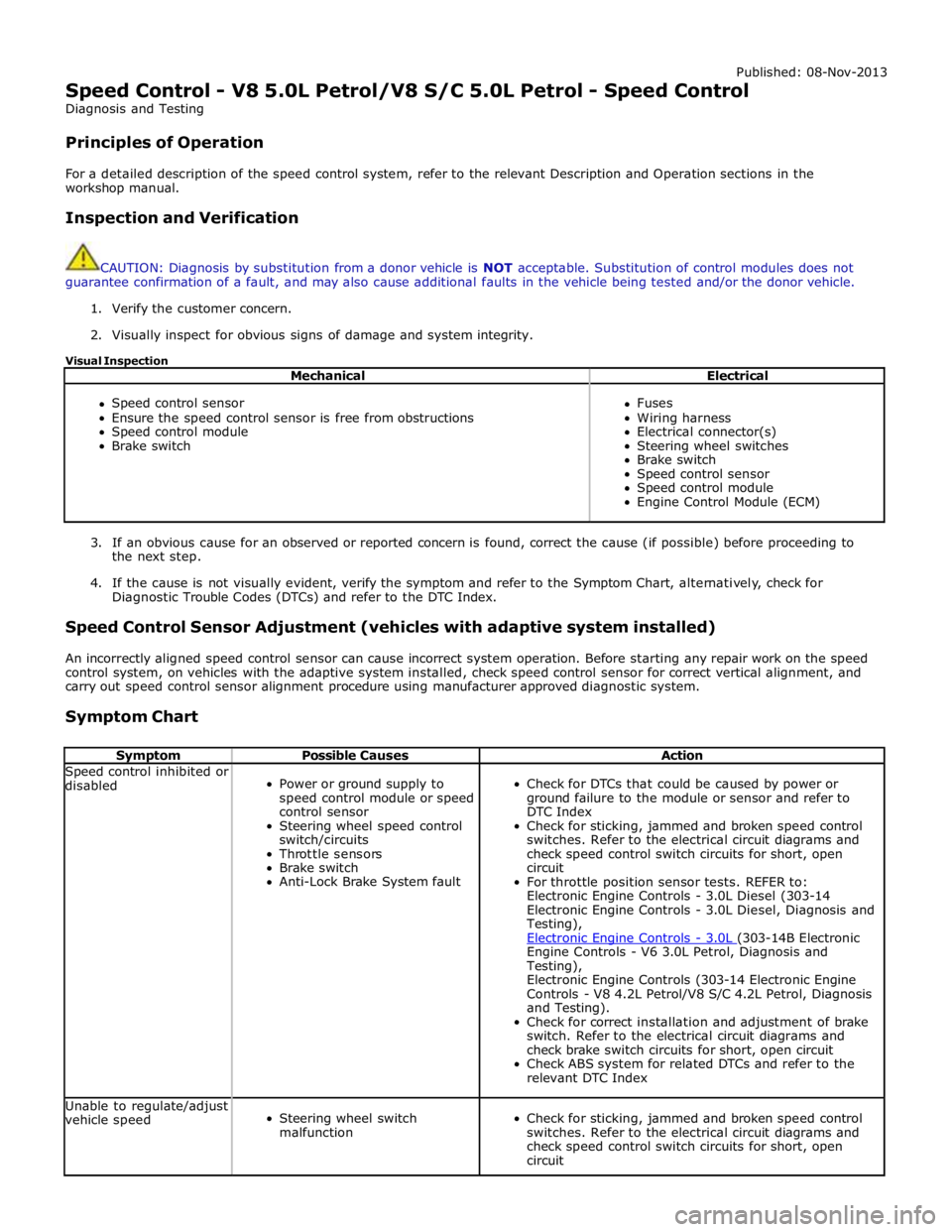
Visual Inspection
Mechanical Electrical
Speed control sensor
Ensure the speed control sensor is free from obstructions
Speed control module
Brake switch
Fuses
Wiring harness
Electrical connector(s)
Steering wheel switches
Brake switch
Speed control sensor
Speed control module
Engine Control Module (ECM)
3. If an obvious cause for an observed or reported concern is found, correct the cause (if possible) before proceeding to
the next step.
4. If the cause is not visually evident, verify the symptom and refer to the Symptom Chart, alternatively, check for
Diagnostic Trouble Codes (DTCs) and refer to the DTC Index.
Speed Control Sensor Adjustment (vehicles with adaptive system installed)
An incorrectly aligned speed control sensor can cause incorrect system operation. Before starting any repair work on the speed
control system, on vehicles with the adaptive system installed, check speed control sensor for correct vertical alignment, and
carry out speed control sensor alignment procedure using manufacturer approved diagnostic system.
Symptom Chart
Symptom Possible Causes Action Speed control inhibited or
disabled
Power or ground supply to
speed control module or speed
control sensor
Steering wheel speed control
switch/circuits
Throttle sensors
Brake switch
Anti-Lock Brake System fault
Check for DTCs that could be caused by power or
ground failure to the module or sensor and refer to
DTC Index
Check for sticking, jammed and broken speed control
switches. Refer to the electrical circuit diagrams and
check speed control switch circuits for short, open
circuit
For throttle position sensor tests. REFER to:
Electronic Engine Controls - 3.0L Diesel (303-14
Electronic Engine Controls - 3.0L Diesel, Diagnosis and
Testing),
Electronic Engine Controls - 3.0L (303-14B Electronic Engine Controls - V6 3.0L Petrol, Diagnosis and
Testing),
Electronic Engine Controls (303-14 Electronic Engine
Controls - V8 4.2L Petrol/V8 S/C 4.2L Petrol, Diagnosis
and Testing).
Check for correct installation and adjustment of brake
switch. Refer to the electrical circuit diagrams and
check brake switch circuits for short, open circuit
Check ABS system for related DTCs and refer to the
relevant DTC Index Unable to regulate/adjust
vehicle speed
Steering wheel switch
malfunction
Check for sticking, jammed and broken speed control
switches. Refer to the electrical circuit diagrams and
check speed control switch circuits for short, open
circuit
Page 2022 of 3039
The lighting system has an 'auto' lights function which is controlled by the CJB on receipt of signals from the rain/light sensor located at the top of the windscreen. The exterior lights are turned on or off in response to ambient light signals from the
rain/light sensor on a LIN (local interconnect network) bus connection to the CJB . The auto lights can also be activated when the windshield wipers are activated by signals from the rain sensor, which is located at the top of the windshield or when the
driver activates the wipers in the fast wipe position.
Two levels of headlamp specification are available; halogen or xenon. In certain markets the headlamps feature a cornering
lamp or a static bending lamp which illuminates the area at the side of the vehicle when turning into driveways for example.
North American Specification (NAS) vehicles have a side marker lamp installed in the headlamp assembly. Replacement of any
of the headlamp bulbs requires removal of the headlamp assembly.
The tail lamp comprises two separate lamp assemblies. The turn signal indicator, side and stop lamps and reverse lamps are
located in each rear fender tail lamp assembly. The rear fog lamps are located in separate units attached to the luggage
compartment lid. A side marker lamp is fitted to the rear fender tail lamp assembly and is fitted in all markets.
Two systems of headlamp leveling are available; manual leveling which is only available on halogen headlamps and static
dynamic leveling which is available on xenon headlamps. The manual system uses a thumbwheel rheostat to adjust the
vertical alignment of the headlamps to compensate for differing vehicle loading. The static dynamic system uses height
sensors fitted to the front and rear suspension and a headlamp leveling module which periodically monitors the vehicle
attitude and adjusts the headlamp vertical alignment accordingly.
Page 2030 of 3039
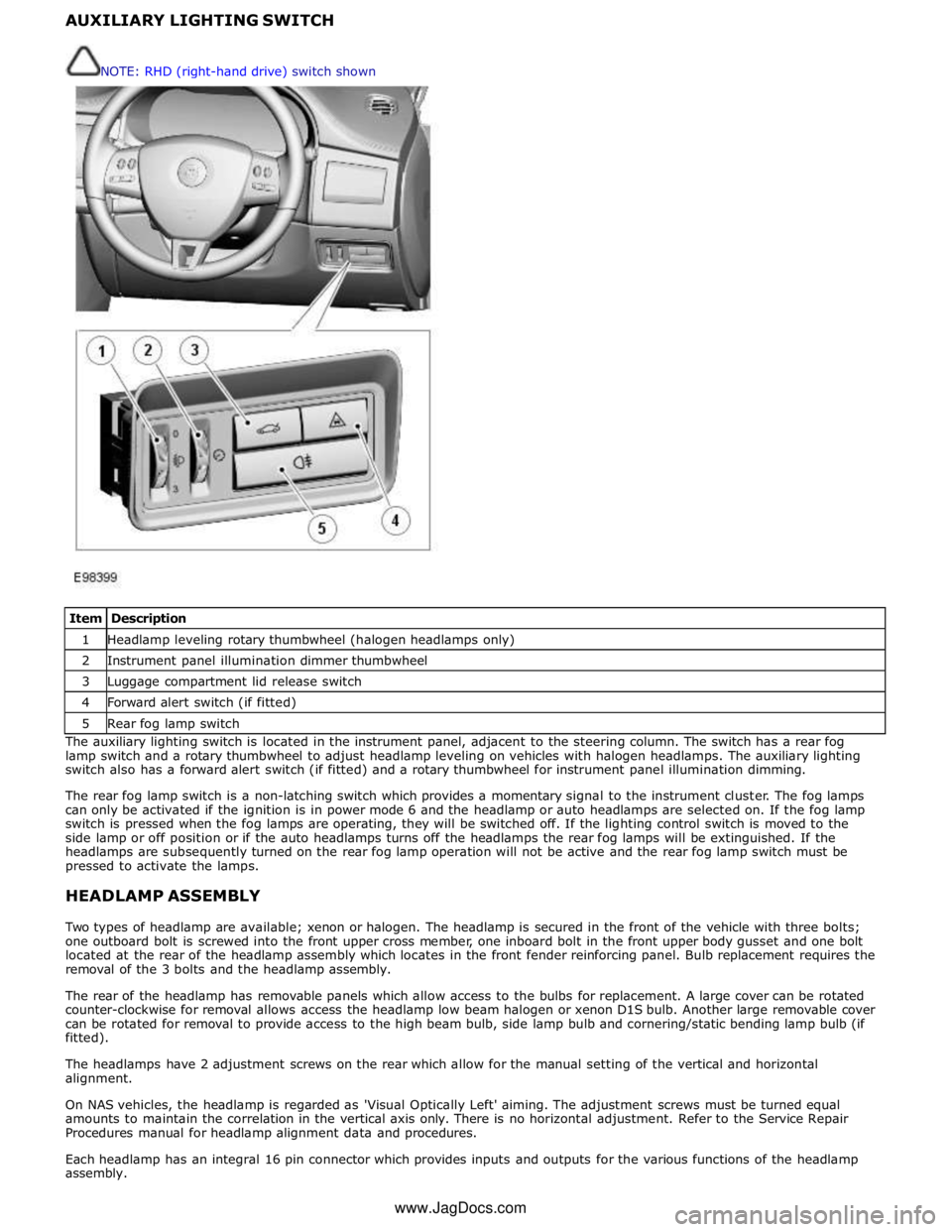
1 Headlamp leveling rotary thumbwheel (halogen headlamps only) 2 Instrument panel illumination dimmer thumbwheel 3 Luggage compartment lid release switch 4 Forward alert switch (if fitted) 5 Rear fog lamp switch The auxiliary lighting switch is located in the instrument panel, adjacent to the steering column. The switch has a rear fog
lamp switch and a rotary thumbwheel to adjust headlamp leveling on vehicles with halogen headlamps. The auxiliary lighting
switch also has a forward alert switch (if fitted) and a rotary thumbwheel for instrument panel illumination dimming.
The rear fog lamp switch is a non-latching switch which provides a momentary signal to the instrument cluster. The fog lamps
can only be activated if the ignition is in power mode 6 and the headlamp or auto headlamps are selected on. If the fog lamp
switch is pressed when the fog lamps are operating, they will be switched off. If the lighting control switch is moved to the
side lamp or off position or if the auto headlamps turns off the headlamps the rear fog lamps will be extinguished. If the
headlamps are subsequently turned on the rear fog lamp operation will not be active and the rear fog lamp switch must be
pressed to activate the lamps.
HEADLAMP ASSEMBLY
Two types of headlamp are available; xenon or halogen. The headlamp is secured in the front of the vehicle with three bolts;
one outboard bolt is screwed into the front upper cross member, one inboard bolt in the front upper body gusset and one bolt
located at the rear of the headlamp assembly which locates in the front fender reinforcing panel. Bulb replacement requires the
removal of the 3 bolts and the headlamp assembly.
The rear of the headlamp has removable panels which allow access to the bulbs for replacement. A large cover can be rotated
counter-clockwise for removal allows access the headlamp low beam halogen or xenon D1S bulb. Another large removable cover
can be rotated for removal to provide access to the high beam bulb, side lamp bulb and cornering/static bending lamp bulb (if
fitted).
The headlamps have 2 adjustment screws on the rear which allow for the manual setting of the vertical and horizontal
alignment.
On NAS vehicles, the headlamp is regarded as 'Visual Optically Left' aiming. The adjustment screws must be turned equal
amounts to maintain the correlation in the vertical axis only. There is no horizontal adjustment. Refer to the Service Repair
Procedures manual for headlamp alignment data and procedures.
Each headlamp has an integral 16 pin connector which provides inputs and outputs for the various functions of the headlamp
assembly. NOTE: RHD (right-hand drive) switch shown
www.JagDocs.com
Page 2034 of 3039
dependant on a particular ignition mode status. The side lamps will also be illuminated when the lighting control switch is in
the AUTO position and a 'lights on' signal is received by the CJB from the rain/light sensor Side Marker Lamps (NAS only)
The side marker lamp is located in the outer part of the headlamp assembly. The side marker lamp uses a W5W wedge fitting
bulb. The bulb is fitted into a holder which connects with contacts in the headlamp housing. The holder is fitted into an
aperture which connects with contacts in the headlamp housing. The side marker lamp is active at all times when the side
lamps are active.
AUTOMATIC HEADLAMP OPERATION
The automatic headlamp function is a driver assistance system. The driver can override the system operation by selection of
side lamp or headlamp on if the ambient light conditions require front and rear lighting to be active. The automatic headlamp
system uses a light sensor and the CJB, which are connected via a LIN (local interconnect network) bus to control the headlamp functionality. The light sensor is incorporated in the rain/light sensor located on the inside of the windshield, below
the rear view mirror. The wiper system also uses the rain/light sensor for automatic wiper operation.
The light sensor measures the ambient light around the vehicle in a vertical direction and also the angular light level from the
front of the vehicle. The rain/light sensor uses vehicle speed signals, wiper switch position and the park position of the front
wipers to control the system. The automatic headlamp operation uses ambient light levels which are monitored by photodiode
incorporated in the rain/light sensor. The rain/light sensor sends a lights on/off request to the CJB on the LIN bus, which responds by switching on the low beam headlamps, front side lamps and rear tail lamps. The automatic headlamps are
activated under the following conditions:
Twilight
Darkness
Rain
Snow
Tunnels
Underground or multistoried car parks.
Operation of the automatic headlamps requires the ignition to be in ignition mode 6, the lighting control switch to be in the
'AUTO' position and a lights on request signal from the light sensor. If the rain sensor signal activates the fast speed wipers,
the low beam headlamps are activated, providing the lighting control switch is in the 'AUTO' position.
HEADLAMP LEVELING
Headlamp leveling provides for the adjustment of the vertical aim of the headlamps. The leveling system is primarily required
to minimise glare to other road users when a heavy load is in the rear of the vehicle. Two systems of headlamp leveling are
available; manual and static dynamic.
Manual Headlamp Leveling
The manual system uses a thumbwheel rheostat to adjust the vertical alignment of the headlamps to compensate for differing
vehicle loading. The rotary thumbwheel is located on the auxiliary lighting switch, adjacent to the illumination dimmer
thumbwheel. Three positions are available to adjust the headlamps to a position to prevent glare to other road users.
Static Dynamic Headlamp Leveling
The static dynamic headlamp leveling system uses the following components:
Front and rear vehicle height sensors
Two headlamp leveling, vertical adjustment motors
Headlamp leveling module
Ignition in mode 6
Vehicle speed information from ABS module.
The static dynamic system uses height sensors fitted to the front and rear suspension and a headlamp leveling module which
periodically monitors the vehicle attitude and adjusts the headlamp vertical alignment accordingly.
Static dynamic headlamp leveling is controlled by a headlamp leveling module located in the lower instrument panel, behind
the glovebox.
The height sensors are both located on the RH side of the vehicle. The front sensor is attached to the front suspension lower arm with a strap and to the front sub frame with a bracket and 2 bolts. The rear sensor is attached to the rear suspension
upper control arm with a cable tied clip and to the rear sub frame with a bracket and 2 bolts. Each sensor has 3 connections to
the headlamp leveling module; power, ground and signal.
DAYTIME RUNNING LAMPS (DRL)
Refer to DRL section for details. Refer to: Daytime Running Lamps (DRL) (417-04 Daytime Running Lamps (DRL), Description and Operation).
REAR LAMP ASSEMBLY
The rear lamp assembly is a 2 piece unit, with one part located in the rear quarter panel and the second part attached to the
luggage compartment lid. The outer rear lamp assembly is located in a recess in the vehicle body. The lamp is secured with 2
studs inboard studs on the lamp body which are secured to the vehicle body with 2 nuts. A third outboard stud and nut secures
Page 2784 of 3039
Front End Sheet Metal Repairs - Front Side Member
Removal and Installation
Removal Published: 11-May-2011
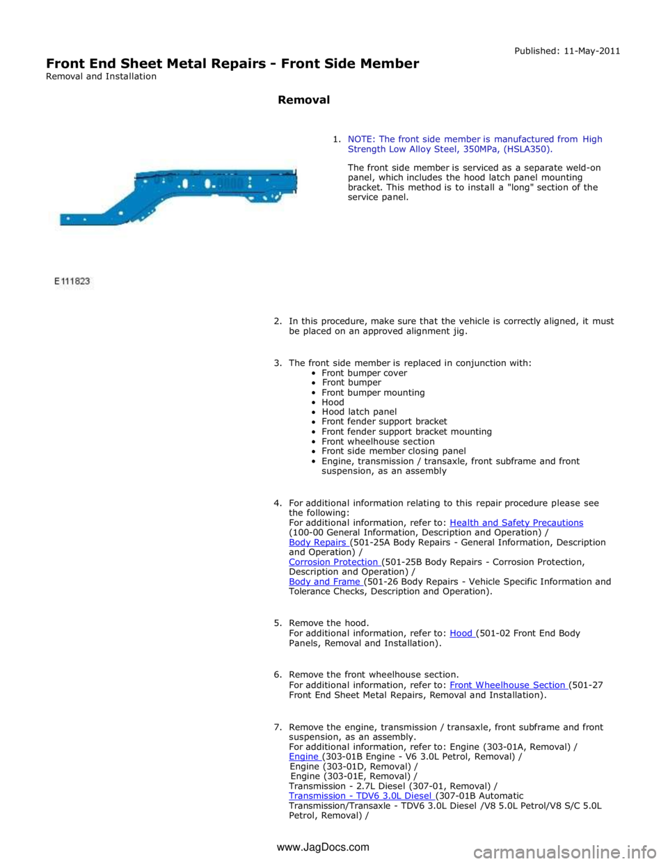
1. NOTE: The front side member is manufactured from High
Strength Low Alloy Steel, 350MPa, (HSLA350).
The front side member is serviced as a separate weld-on
panel, which includes the hood latch panel mounting
bracket. This method is to install a "long" section of the
service panel.
2. In this procedure, make sure that the vehicle is correctly aligned, it must
be placed on an approved alignment jig.
3. The front side member is replaced in conjunction with:
Front bumper cover
Front bumper
Front bumper mounting
Hood
Hood latch panel
Front fender support bracket
Front fender support bracket mounting
Front wheelhouse section
Front side member closing panel
Engine, transmission / transaxle, front subframe and front
suspension, as an assembly
4. For additional information relating to this repair procedure please see
the following:
For additional information, refer to: Health and Safety Precautions (100-00 General Information, Description and Operation) /
Body Repairs (501-25A Body Repairs - General Information, Description and Operation) /
Corrosion Protection (501-25B Body Repairs - Corrosion Protection, Description and Operation) /
Body and Frame (501-26 Body Repairs - Vehicle Specific Information and Tolerance Checks, Description and Operation).
5. Remove the hood.
For additional information, refer to: Hood (501-02 Front End Body Panels, Removal and Installation).
6. Remove the front wheelhouse section.
For additional information, refer to: Front Wheelhouse Section (501-27 Front End Sheet Metal Repairs, Removal and Installation).
7. Remove the engine, transmission / transaxle, front subframe and front
suspension, as an assembly.
For additional information, refer to: Engine (303-01A, Removal) /
Engine (303-01B Engine - V6 3.0L Petrol, Removal) / Engine (303-01D, Removal) /
Engine (303-01E, Removal) /
Transmission - 2.7L Diesel (307-01, Removal) /
Transmission - TDV6 3.0L Diesel (307-01B Automatic Transmission/Transaxle - TDV6 3.0L Diesel /V8 5.0L Petrol/V8 S/C 5.0L
Petrol, Removal) / www.JagDocs.com
Page 2807 of 3039
Published: 11-May-2011
Front End Sheet Metal Repairs - Front Side Member Closing Panel
Removal and Installation
Removal
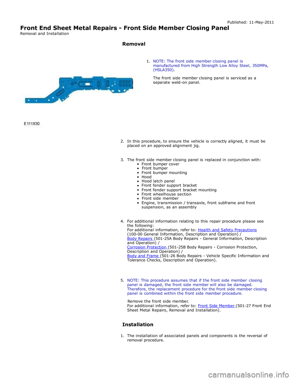
1. NOTE: The front side member closing panel is
manufactured from High Strength Low Alloy Steel, 350MPa,
(HSLA350).
The front side member closing panel is serviced as a
separate weld-on panel.
2. In this procedure, to ensure the vehicle is correctly aligned, it must be
placed on an approved alignment jig.
3. The front side member closing panel is replaced in conjunction with:
Front bumper cover
Front bumper
Front bumper mounting
Hood
Hood latch panel
Front fender support bracket
Front fender support bracket mounting
Front wheelhouse section
Front side member
Engine, transmission / transaxle, front subframe and front
suspension, as an assembly
4. For additional information relating to this repair procedure please see
the following:
For additional information, refer to: Health and Safety Precautions (100-00 General Information, Description and Operation) /
Body Repairs (501-25A Body Repairs - General Information, Description and Operation) /
Corrosion Protection (501-25B Body Repairs - Corrosion Protection, Description and Operation) /
Body and Frame (501-26 Body Repairs - Vehicle Specific Information and Tolerance Checks, Description and Operation).
5. NOTE: This procedure assumes that if the front side member closing
panel is damaged, the front side member will also be damaged.
Therefore, the replacement procedure for the front side member closing
panel is combined within the front side member procedure.
Remove the front side member.
For additional information, refer to: Front Side Member (501-27 Front End Sheet Metal Repairs, Removal and Installation).
Installation
1. The installation of associated panels and components is the reversal of
removal procedure.
Page 2974 of 3039
Rear End Sheet Metal Repairs - Rear Side Member Section
Removal and Installation
Removal Published: 11-May-2011
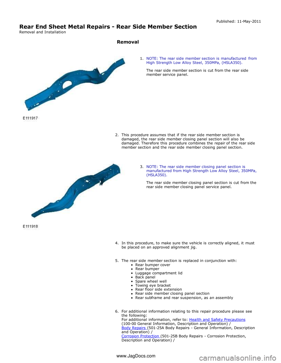
1. NOTE: The rear side member section is manufactured from
High Strength Low Alloy Steel, 350MPa, (HSLA350).
The rear side member section is cut from the rear side
member service panel.
2. This procedure assumes that if the rear side member section is
damaged, the rear side member closing panel section will also be
damaged. Therefore this procedure combines the repair of the rear side
member section and the rear side member closing panel section.
3. NOTE: The rear side member closing panel section is
manufactured from High Strength Low Alloy Steel, 350MPa,
(HSLA350).
The rear side member closing panel section is cut from the
rear side member closing panel service panel.
4. In this procedure, to make sure the vehicle is correctly aligned, it must
be placed on an approved alignment jig.
5. The rear side member section is replaced in conjunction with:
Rear bumper cover
Rear bumper
Luggage compartment lid
Back panel
Spare wheel well
Towing eye bracket
Rear floor side extension
Rear side member closing panel section
Rear subframe and rear suspension, as an assembly
6. For additional information relating to this repair procedure please see
the following:
For additional information, refer to: Health and Safety Precautions (100-00 General Information, Description and Operation) /
Body Repairs (501-25A Body Repairs - General Information, Description and Operation) /
Corrosion Protection (501-25B Body Repairs - Corrosion Protection, Description and Operation) / www.JagDocs.com
Page 2986 of 3039
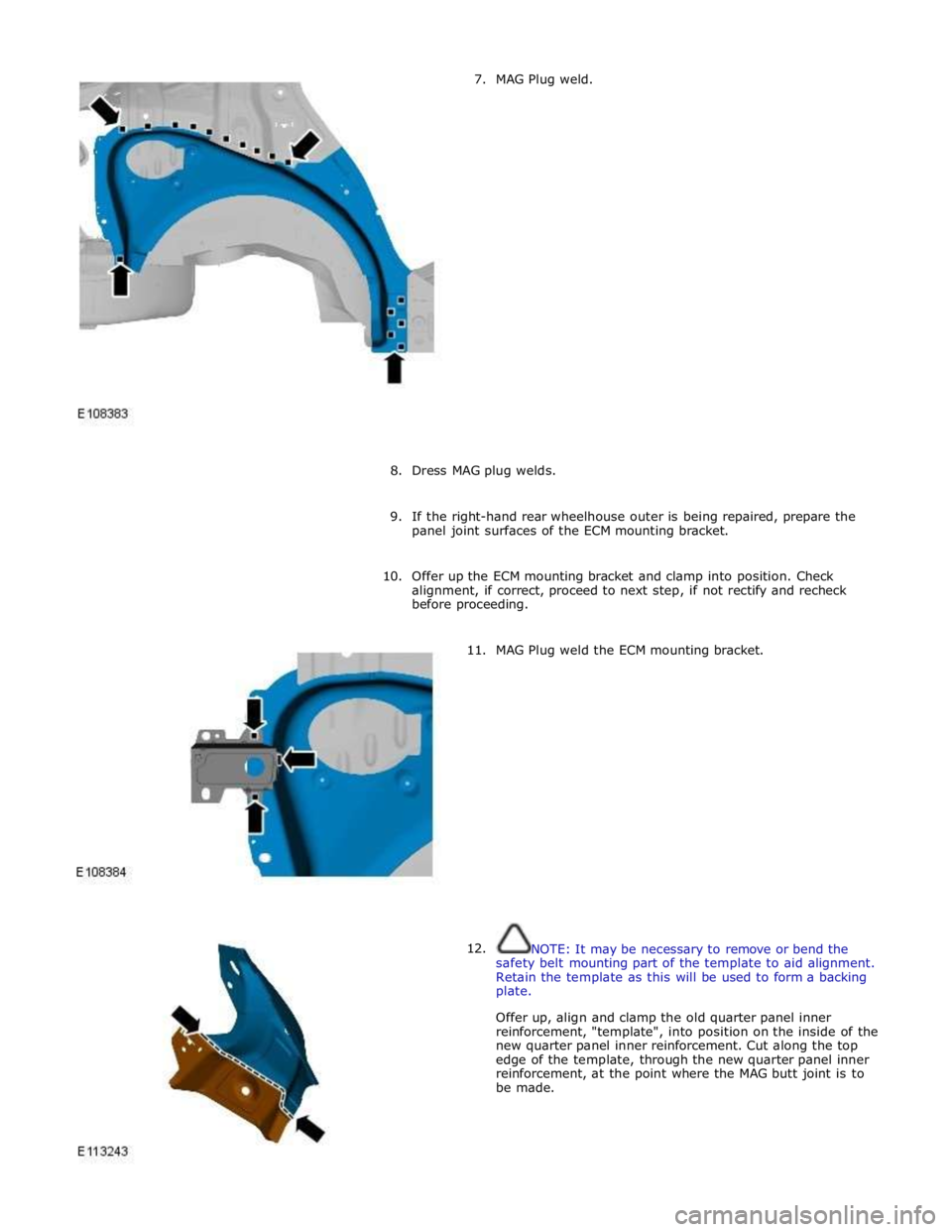
7. MAG Plug weld.
8. Dress MAG plug welds.
9. If the right-hand rear wheelhouse outer is being repaired, prepare the
panel joint surfaces of the ECM mounting bracket.
10. Offer up the ECM mounting bracket and clamp into position. Check
alignment, if correct, proceed to next step, if not rectify and recheck
before proceeding.
11.
12. MAG Plug weld the ECM mounting bracket.
NOTE: It may be necessary to remove or bend the
safety belt mounting part of the template to aid alignment.
Retain the template as this will be used to form a backing
plate.
Offer up, align and clamp the old quarter panel inner
reinforcement, "template", into position on the inside of the
new quarter panel inner reinforcement. Cut along the top
edge of the template, through the new quarter panel inner
reinforcement, at the point where the MAG butt joint is to
be made.
Page 3005 of 3039
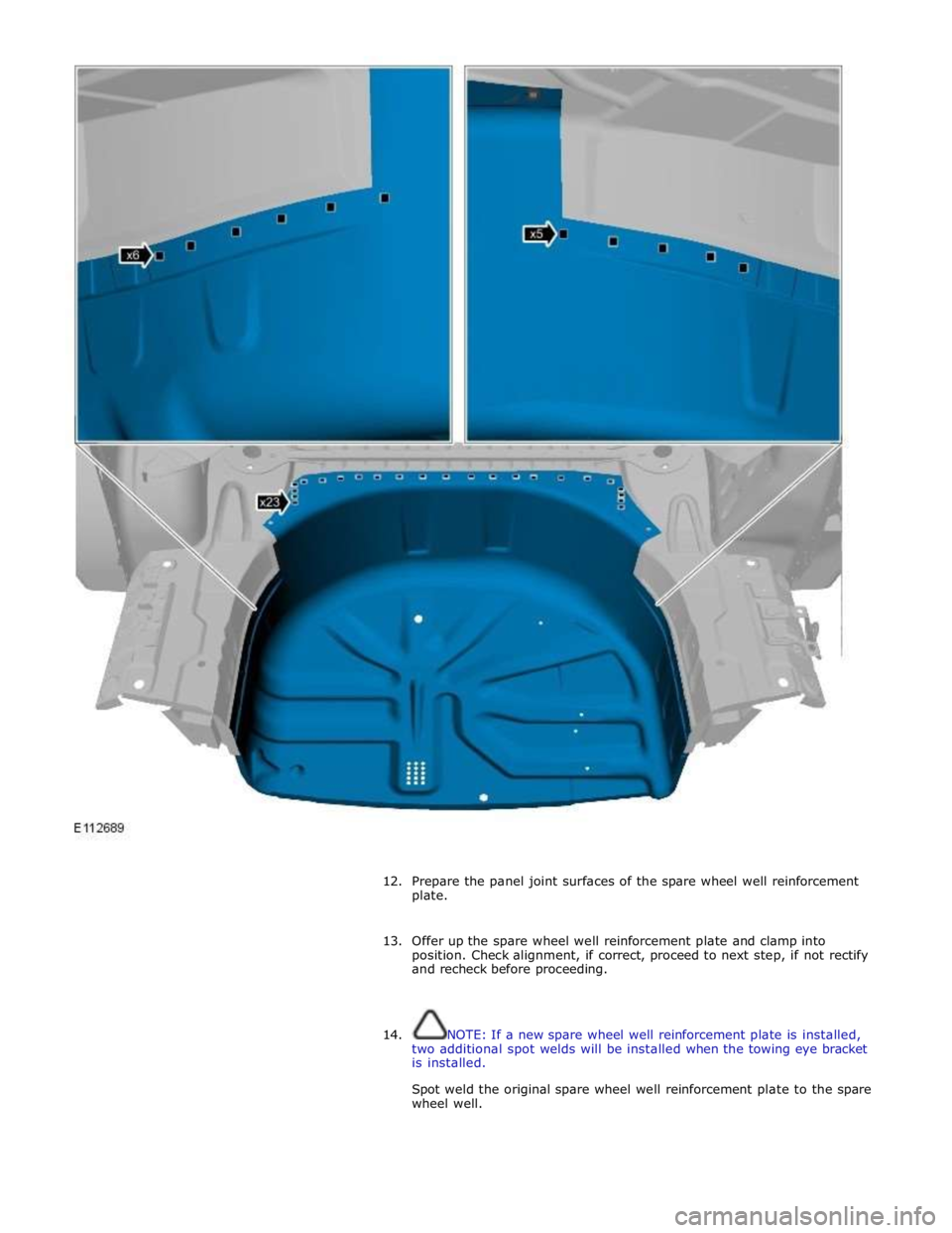
12. Prepare the panel joint surfaces of the spare wheel well reinforcement
plate.
13. Offer up the spare wheel well reinforcement plate and clamp into
position. Check alignment, if correct, proceed to next step, if not rectify
and recheck before proceeding.
14. NOTE: If a new spare wheel well reinforcement plate is installed,
two additional spot welds will be installed when the towing eye bracket
is installed.
Spot weld the original spare wheel well reinforcement plate to the spare
wheel well.