wheel alignment JAGUAR XFR 2010 1.G User Guide
[x] Cancel search | Manufacturer: JAGUAR, Model Year: 2010, Model line: XFR, Model: JAGUAR XFR 2010 1.GPages: 3039, PDF Size: 58.49 MB
Page 310 of 3039
Shock Absorber and Spring Assembly (204-02 Rear Suspension, Removal and Installation). * Loose front stabilizer bar or rear
stabilizer bar. * Check and tighten the stabilizer bar to specification.
REFER to:
Specifications (204-01 Front Suspension, Specifications), Specifications (204-02 Rear Suspension, Specifications). * Worn lower suspension arm stabilizer
bar insulators. * Install new lower suspension arm stabilizer bar as
necessary. REFER to:
Front Stabilizer Bar - 2.7L Diesel (204-01, Removal and
Installation),
Front Stabilizer Bar - V6 3.0L Petrol (204-01 Front Suspension, Removal and Installation),
Front Stabilizer Bar - 4.2L (204-01, Removal and
Installation),
Rear Stabilizer Bar (204-02 Rear Suspension, Removal and Installation). * Shock absorber(s). * Check and install new shock absorber(s) as necessary.
REFER to:
Front Shock Absorber (204-01 Front Suspension, Removal and Installation),
Shock Absorber and Spring Assembly (204-02 Rear Suspension, Removal and Installation). Vehicle Leans to One
Side * Unevenly loaded or overloaded vehicle. * Notify the customer of incorrect vehicle loading. * Front or rear suspension components.
* Inspect the front and rear suspension systems. Repair or
install new suspension components as necessary. * Shock absorber(s). * Check and install new shock absorber(s) as necessary.
REFER to:
Front Shock Absorber (204-01 Front Suspension, Removal and Installation),
Shock Absorber and Spring Assembly (204-02 Rear Suspension, Removal and Installation). * Coil spring(s).
* Check and install new spring(s) as necessary. REFER to:
Front Shock Absorber (204-01 Front Suspension, Removal and Installation),
Shock Absorber and Spring Assembly (204-02 Rear Suspension, Removal and Installation). * Incorrect ride height. Lateral tilt out of
specification. * Check the ride height. Install new spring(s) as
necessary. REFER to:
Front Shock Absorber (204-01 Front Suspension, Removal and Installation),
Shock Absorber and Spring Assembly (204-02 Rear Suspension, Removal and Installation). Vibration/Noise * Tires/wheels.
* Wheel bearings.
* Wheel hubs.
* Brake components.
* Suspension components.
* Steering components. * Check and install new components as necessary. Wander * Unevenly loaded or overloaded vehicle. * Notify the customer of incorrect vehicle loading. * Ball joint(s). * Check the Ball Joint(s). * Front wheel bearing(s). * Check the wheel bearings. * Loose, worn or damaged suspension components. * Check and install new suspension components as necessary. * Loose suspension fasteners.
* Check and tighten the suspension fasteners to
specification.
REFER to: Specifications (204-00 Suspension System - General Information, Specifications). * Steering components. * Check and install new steering components. * Wheel alignment (excessive total front
toe-out). * Check and adjust the wheel alignment. REFER to:
(204-00 Suspension System - General Information)
Front Toe Adjustment (General Procedures), Rear Toe Adjustment (General Procedures), Camber and Caster Adjustment (General Procedures). Component Tests
Ball Joint Inspection
NOTE: The front suspension is shown in the following procedures. The inspection of the rear suspension upper ball joint
is similar.
1. Raise and support the vehicle. REFER to: (100-02 Jacking and Lifting)
Jacking (Description and Operation), Lifting (Description and Operation).
2. Prior to carrying out any inspection of the ball joints, inspect the front wheel bearings.
Page 317 of 3039
Published: 16-Oct-2013
Suspension System - General Information - Four-Wheel Alignment
General Procedures
CAUTIONS:
Make sure the vehicle is on a flat level surface.
Make sure the tire pressures are within specification.
Make sure that only the manufacturers' recommended four wheel alignment equipment is used.
Make sure the steering is in the straight ahead position.
1. For wheel alignment information, refer to the suspension specification
section.
For additional information, refer to: Specifications (204-00 Suspension System - General Information, Specifications).
2. Check the tie rod ends, suspension joints, wheel bearings and wheels
and tires for damage, wear and free play.
Adjust or repair any worn, damaged or incorrectly adjusted
components.
3. Check and adjust tire pressures.
4. Position the vehicle on a calibrated, level, vehicle lift.
5. Vehicles with air suspension.
For additional information, refer to: Air Suspension Manual Tight
Tolerance Setting Mode (204-05, General Procedures).
6. Release the vehicle parking brake.
7. Using only four-wheel alignment equipment approved by Jaguar, check
the wheel alignment.
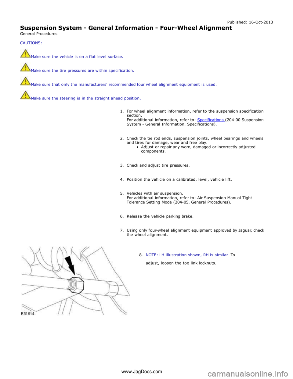
8. NOTE: LH illustration shown, RH is similar. To
adjust, loosen the toe link locknuts. www.JagDocs.com
Page 320 of 3039
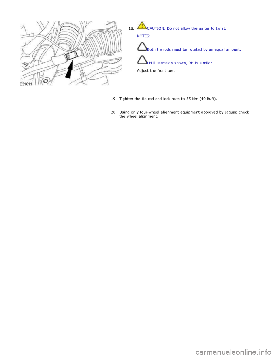
18. CAUTION: Do not allow the gaiter to twist.
NOTES:
Both tie rods must be rotated by an equal amount.
LH illustration shown, RH is similar.
Adjust the front toe.
19. Tighten the tie rod end lock nuts to 55 Nm (40 lb.ft).
20. Using only four-wheel alignment equipment approved by Jaguar, check
the wheel alignment.
Page 321 of 3039
Published: 16-Oct-2013
Suspension System - General Information - Front Toe Adjustment
General Procedures
CAUTIONS:
Make sure the vehicle is on a flat level surface.
Make sure the tire pressures are within specification.
Make sure that only the manufacturers' recommended four wheel alignment equipment is used.
Make sure the steering is in the straight ahead position.
1. For wheel alignment information, refer to the suspension specification
section.
For additional information, refer to: Specifications (204-00 Suspension System - General Information, Specifications).
2. Check the tie rod ends, suspension joints, wheel bearings and wheels
and tires for damage, wear and free play.
Adjust or repair any worn, damaged or incorrectly adjusted
components.
3. Check and adjust tire pressures.
4. Position the vehicle on a 4 post lift.
5. Release the vehicle parking brake.
6. Vehicles with air suspension.
For additional information, refer to: Air Suspension Manual Tight
Tolerance Setting Mode (204-05, General Procedures).
7. For additional information, refer to: Air Suspension Manual Tight
Tolerance Setting Mode (204-05, General Procedures).
8. Using only four-wheel alignment equipment approved by Jaguar, check
the wheel alignment.
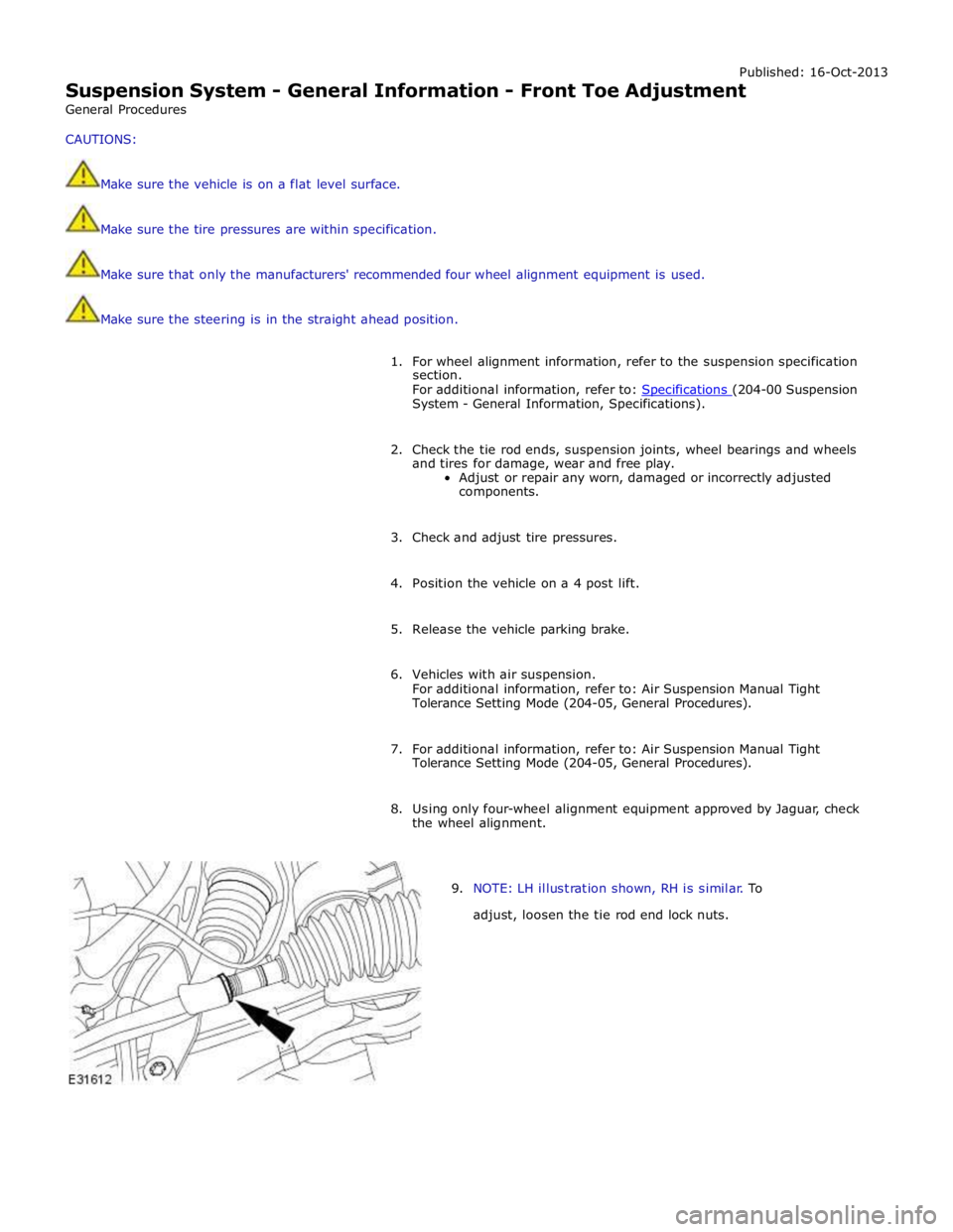
9. NOTE: LH illustration shown, RH is similar. To
adjust, loosen the tie rod end lock nuts.
Page 322 of 3039
10.
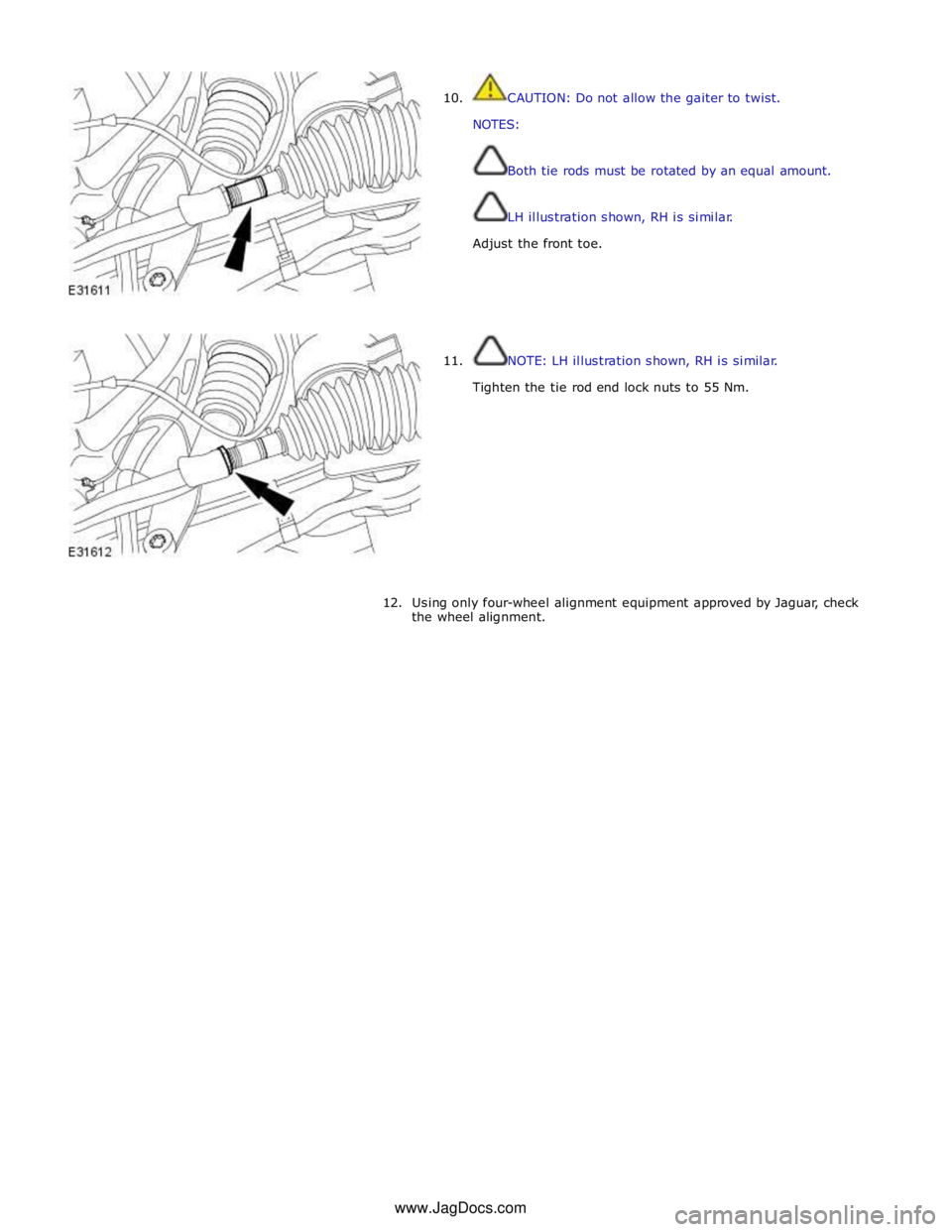
11. CAUTION: Do not allow the gaiter to twist.
NOTES:
Both tie rods must be rotated by an equal amount.
LH illustration shown, RH is similar.
Adjust the front toe.
NOTE: LH illustration shown, RH is similar.
Tighten the tie rod end lock nuts to 55 Nm.
12. Using only four-wheel alignment equipment approved by Jaguar, check
the wheel alignment. www.JagDocs.com
Page 343 of 3039
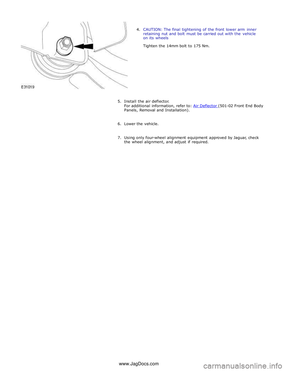
Panels, Removal and Installation).
6. Lower the vehicle.
7. Using only four-wheel alignment equipment approved by Jaguar, check
the wheel alignment, and adjust if required. www.JagDocs.com
Page 349 of 3039
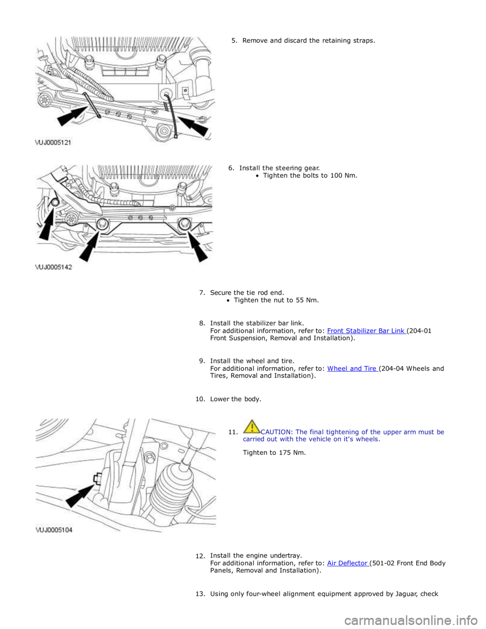
5. Remove and discard the retaining straps.
6. Install the steering gear.
Tighten the bolts to 100 Nm.
7. Secure the tie rod end.
Tighten the nut to 55 Nm.
8. Install the stabilizer bar link.
For additional information, refer to: Front Stabilizer Bar Link (204-01 Front Suspension, Removal and Installation).
9. Install the wheel and tire.
For additional information, refer to: Wheel and Tire (204-04 Wheels and Tires, Removal and Installation).
10. Lower the body.
11. CAUTION: The final tightening of the upper arm must be
carried out with the vehicle on it's wheels.
Tighten to 175 Nm.
12.
Install the engine undertray.
For additional information, refer to: Air Deflector (501-02 Front End Body Panels, Removal and Installation).
13. Using only four-wheel alignment equipment approved by Jaguar, check
Page 421 of 3039
System - V6 3.0L Petrol, Removal and Installation).
19. Refill the fuel tank.
For additional information, refer to: Fuel Tank Draining (310-00 Fuel System - General Information, General Procedures).
20. Bleed the brake system.
For additional information, refer to: Brake System Bleeding (206-00 Brake System - General Information, General Procedures).
21. Install the rear wheels and tires.
For additional information, refer to: Wheel and Tire (204-04 Wheels and Tires, Removal and Installation).
22. Connect the battery ground cable.
For additional information, refer to: Battery Disconnect and Connect (414-01 Battery, Mounting and Cables, General Procedures).
23. Using only four-wheel alignment equipment approved by Jaguar, check
and adjust the wheel alignment.
For additional information, refer to: Camber and Caster Adjustment (204-00 Suspension System - General Information, General Procedures).
Page 427 of 3039
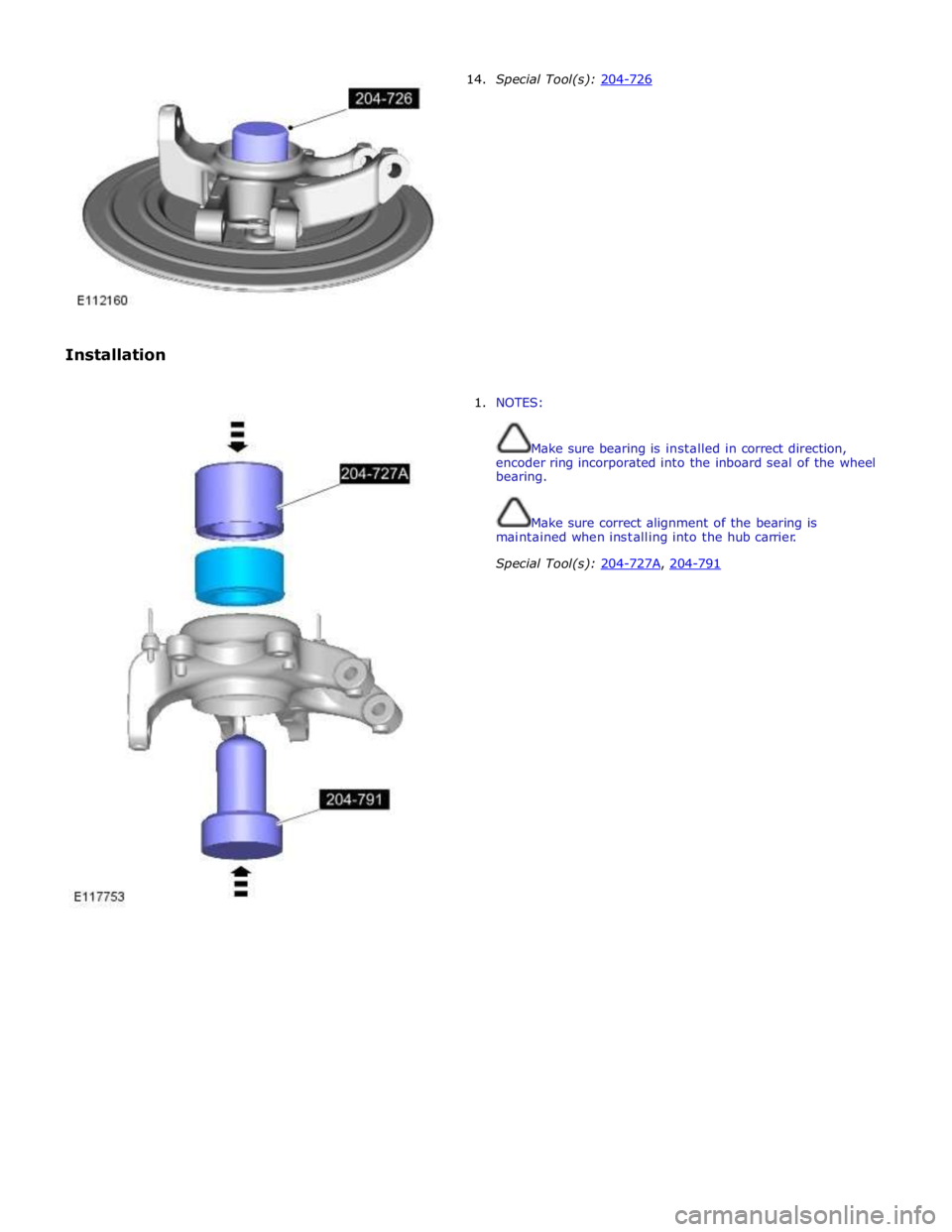
Installation 14. Special Tool(s): 204-726
1. NOTES:
Make sure bearing is installed in correct direction,
encoder ring incorporated into the inboard seal of the wheel
bearing.
Make sure correct alignment of the bearing is
maintained when installing into the hub carrier.
Special Tool(s): 204-727A, 204-791
Page 428 of 3039
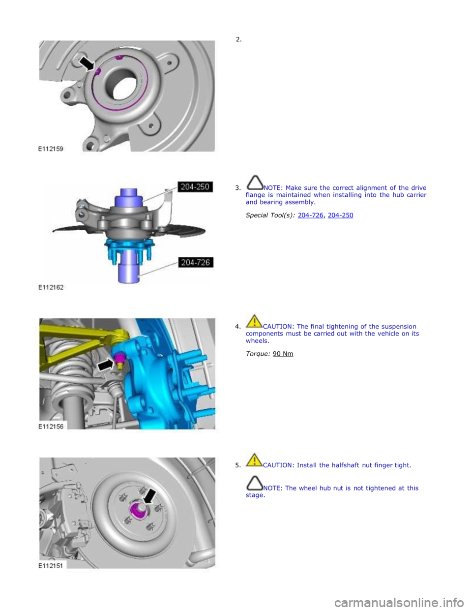
2.
3. NOTE: Make sure the correct alignment of the drive
flange is maintained when installing into the hub carrier
and bearing assembly.
Special Tool(s): 204-726, 204-250
4. CAUTION: The final tightening of the suspension
components must be carried out with the vehicle on its
wheels.
Torque: 90 Nm
5. CAUTION: Install the halfshaft nut finger tight.
NOTE: The wheel hub nut is not tightened at this
stage.