sensor JAGUAR XFR 2010 1.G Workshop Manual
[x] Cancel search | Manufacturer: JAGUAR, Model Year: 2010, Model line: XFR, Model: JAGUAR XFR 2010 1.GPages: 3039, PDF Size: 58.49 MB
Page 2440 of 3039
Glass, Frames and Mechanisms - Windshield Glass
Removal and Installation
Removal
NOTE: Removal steps in this procedure may contain installation details. Published: 04-Sep-2013
1. Refer to: Cowl Vent Screen (501-02 Front End Body Panels, Removal and Installation).
2. Refer to: A-Pillar Trim Panel (501-05 Interior Trim and Ornamentation, Removal and Installation).
3. Refer to: Rain Sensor (501-16 Wipers and Washers, Removal and Installation).
4.
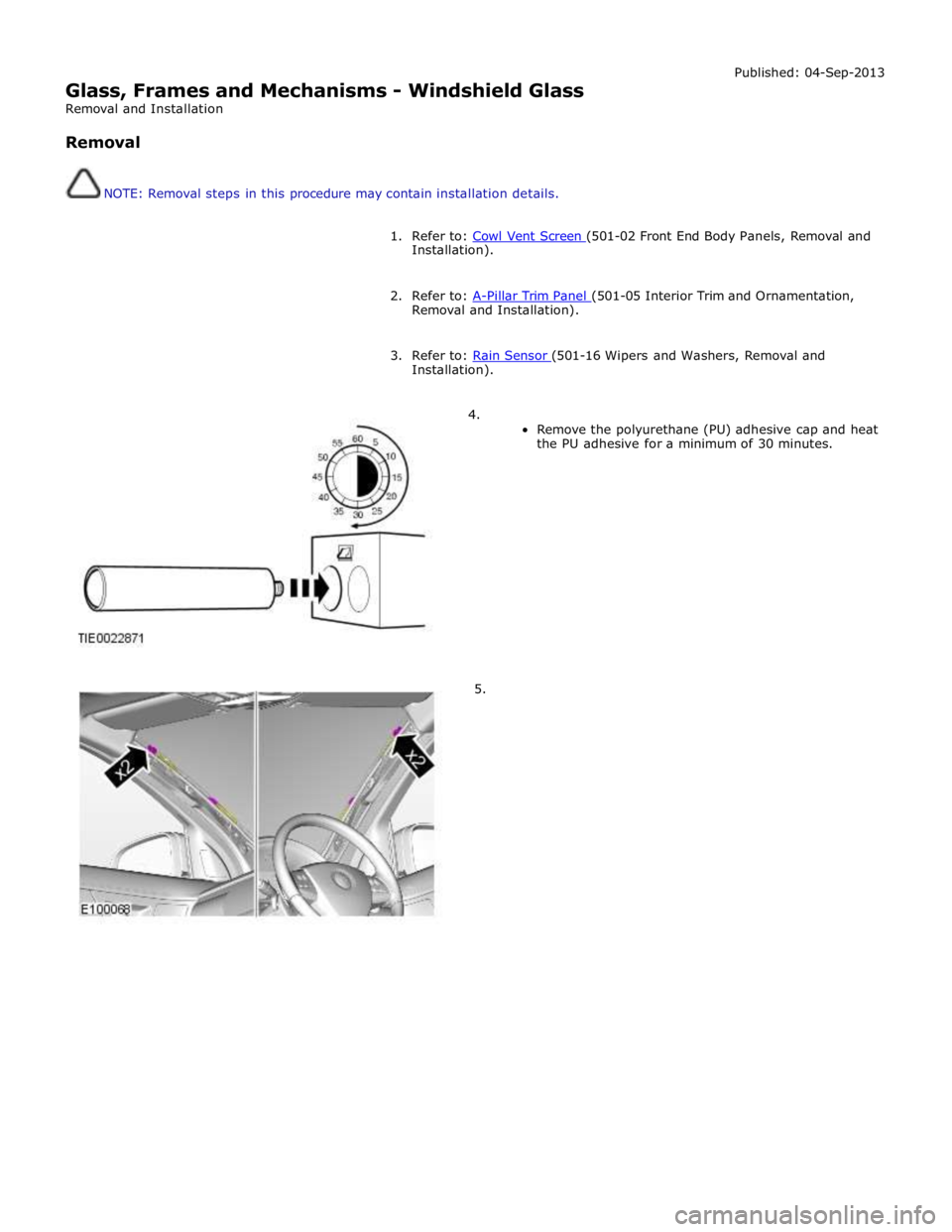
Remove the polyurethane (PU) adhesive cap and heat
the PU adhesive for a minimum of 30 minutes.
5.
Page 2534 of 3039
Published: 11-May-2011
Wipers and Washers - Wipers and Washers - Component Location
Description and Operation
COMPONENT LOCATION
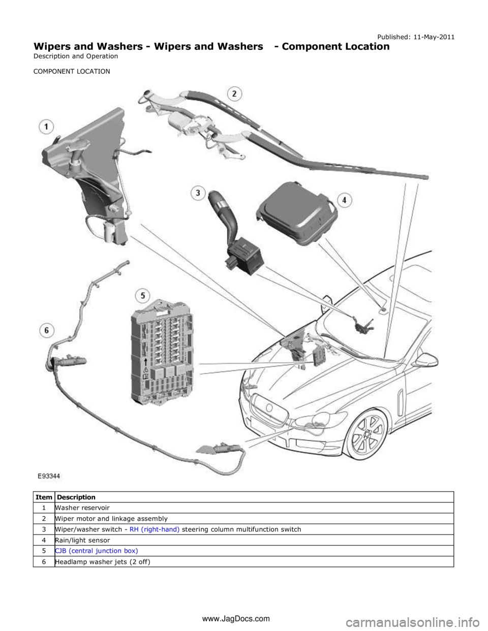
Item Description 1 Washer reservoir 2 Wiper motor and linkage assembly 3 Wiper/washer switch - RH (right-hand) steering column multifunction switch 4 Rain/light sensor 5 CJB (central junction box) 6 Headlamp washer jets (2 off) www.JagDocs.com
Page 2535 of 3039
Wipers and Washers - Wipers and Washers - Overview
Description and Operation
OVERVIEW Published: 11-May-2011
The wipers and washers comprise a windshield wiper system with a conventional wiper linkage and 2 wiper blades and a
windshield washer with jets located on the wiper arms. A headlamp powerwash is available on certain models.
The front wipers have 4 operational states:
Flick wipe
Auto
Slow wipe
Fast wipe.
Operation of the windshield wipers and washers and the headlamp powerwash is controlled by the CJB (central junction box) in
response to driver inputs and signals from the rain/light sensor. The instrument cluster monitors the condition of the
wiper/washer control switch and transmits driver requests to the CJB over the medium speed CAN (controller area network) bus.
The 'Auto' function requires an input from the rain sensor. The rain sensor is mounted on the inner surface of the windshield
and transmits an infra-red signal to determine the amount of water on the outer surface of the windshield. A value is then
transmitted to the CJB over the LIN (local interconnect network) bus.
Page 2536 of 3039

Published: 11-May-2011
Wipers and Washers - Wipers and Washers - System Operation and
Component Description
Description and Operation
Control Diagram
NOTE: A = Hardwired; N = Medium speed CAN (controller area network) bus; O = LIN (local interconnect network) bus
Item Description 1 Battery 2 EJB (engine junction box) 3 Wiper motor 4 Headlamp washer pump 5 Rain/Light sensor 6 Washer reservoir fluid level switch
Page 2537 of 3039
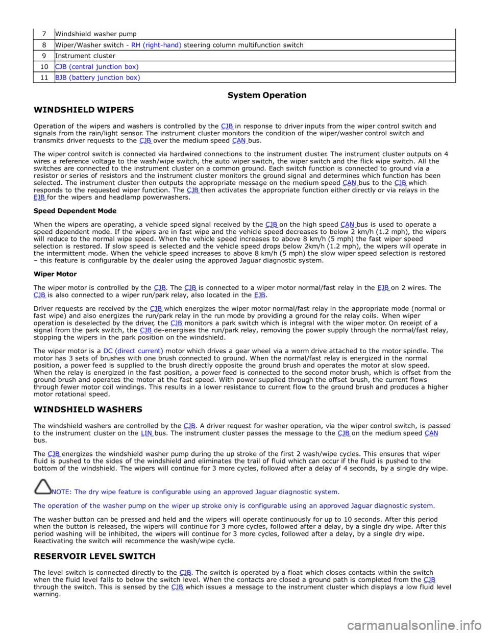
7 Windshield washer pump 8 Wiper/Washer switch - RH (right-hand) steering column multifunction switch 9 Instrument cluster 10 CJB (central junction box) 11 BJB (battery junction box)
WINDSHIELD WIPERS System Operation
Operation of the wipers and washers is controlled by the CJB in response to driver inputs from the wiper control switch and signals from the rain/light sensor. The instrument cluster monitors the condition of the wiper/washer control switch and
transmits driver requests to the CJB over the medium speed CAN bus.
The wiper control switch is connected via hardwired connections to the instrument cluster. The instrument cluster outputs on 4
wires a reference voltage to the wash/wipe switch, the auto wiper switch, the wiper switch and the flick wipe switch. All the
switches are connected to the instrument cluster on a common ground. Each switch function is connected to ground via a
resistor or series of resistors and the instrument cluster monitors the ground signal and determines which function has been
selected. The instrument cluster then outputs the appropriate message on the medium speed CAN bus to the CJB which responds to the requested wiper function. The CJB then activates the appropriate function either directly or via relays in the EJB for the wipers and headlamp powerwashers. Speed Dependent Mode
When the wipers are operating, a vehicle speed signal received by the CJB on the high speed CAN bus is used to operate a speed dependent mode. If the wipers are in fast wipe and the vehicle speed decreases to below 2 km/h (1.2 mph), the wipers
will reduce to the normal wipe speed. When the vehicle speed increases to above 8 km/h (5 mph) the fast wiper speed
selection is restored. If slow speed is selected and the vehicle speed drops below 2km/h (1.2 mph), the wipers will operate in
the intermittent mode. When the vehicle speed increases to above 8 km/h (5 mph) the slow wiper speed selection is restored
– this feature is configurable by the dealer using the approved Jaguar diagnostic system.
Wiper Motor
The wiper motor is controlled by the CJB. The CJB is connected to a wiper motor normal/fast relay in the EJB on 2 wires. The CJB is also connected to a wiper run/park relay, also located in the EJB.
Driver requests are received by the CJB which energizes the wiper motor normal/fast relay in the appropriate mode (normal or fast wipe) and also energizes the run/park relay in the run mode by providing a ground for the relay coils. When wiper
operation is deselected by the driver, the CJB monitors a park switch which is integral with the wiper motor. On receipt of a signal from the park switch, the CJB de-energises the run/park relay, removing the power supply through the normal/fast relay, stopping the wipers in the park position on the windshield.
The wiper motor is a DC (direct current) motor which drives a gear wheel via a worm drive attached to the motor spindle. The
motor has 3 sets of brushes with one brush connected to ground. When the normal/fast relay is energized in the normal
position, a power feed is supplied to the brush directly opposite the ground brush and operates the motor at slow speed.
When the relay is energized in the fast position, a power feed is connected to the second motor brush, which is offset from the
ground brush and operates the motor at the fast speed. With power supplied through the offset brush, the current flows
through fewer motor coil windings. This results in a lower resistance to current flow to the ground brush and produces a higher
motor rotational speed.
WINDSHIELD WASHERS
The windshield washers are controlled by the CJB. A driver request for washer operation, via the wiper control switch, is passed to the instrument cluster on the LIN bus. The instrument cluster passes the message to the CJB on the medium speed CAN bus.
The CJB energizes the windshield washer pump during the up stroke of the first 2 wash/wipe cycles. This ensures that wiper fluid is pushed to the sides of the windshield and eliminates the trail of fluid which can occur if the fluid is pushed to the
bottom of the windshield. The wipers will continue for 3 more cycles, followed after a delay of 4 seconds, by a single dry wipe.
NOTE: The dry wipe feature is configurable using an approved Jaguar diagnostic system.
The operation of the washer pump on the wiper up stroke only is configurable using an approved Jaguar diagnostic system.
The washer button can be pressed and held and the wipers will operate continuously for up to 10 seconds. After this period
when the button is released, the wipers will continue for 3 more cycles, followed after a delay, by a single dry wipe. After this
period washing will be inhibited, the wipers will continue for 3 more cycles, followed after a delay, by a single dry wipe.
Reactivating the switch will recommence the wash/wipe cycle.
RESERVOIR LEVEL SWITCH
The level switch is connected directly to the CJB. The switch is operated by a float which closes contacts within the switch when the fluid level falls to below the switch level. When the contacts are closed a ground path is completed from the CJB through the switch. This is sensed by the CJB which issues a message to the instrument cluster which displays a low fluid level warning.
Page 2538 of 3039
HEADLAMP POWERWASHERS
The headlamp powerwash is activated when the driver requests windshield washer operation. The CJB receives the driver request via a CAN bus message from the instrument cluster. The CJB then checks for an exterior lights active signal and that a low washer fluid level signal is not present.
The CJB outputs a control voltage to a headlamp powerwash pump relay located in the EJB. The relay is energized by the CJB for a pre-determined period to allow the headlamp telescopic washers to operate.
The CJB monitors the driver washer requests and only operates the headlamp powerwash on every fourth request for windshield washer operation, provided that 10 minutes have elapsed since the last headlamp powerwash operation. The
powerwash sequence is reset when the headlamps or the ignition is switched off.
NOTE: If a low fluid reservoir level is present the CJB prohibits headlamp powerwash.
RAIN/LIGHT SENSOR
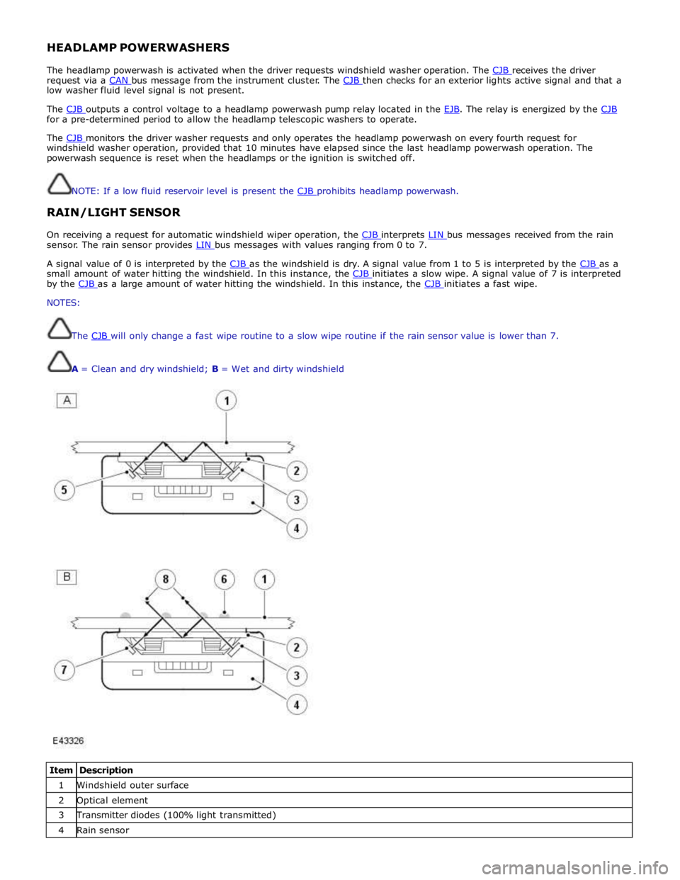
On receiving a request for automatic windshield wiper operation, the CJB interprets LIN bus messages received from the rain sensor. The rain sensor provides LIN bus messages with values ranging from 0 to 7.
A signal value of 0 is interpreted by the CJB as the windshield is dry. A signal value from 1 to 5 is interpreted by the CJB as a small amount of water hitting the windshield. In this instance, the CJB initiates a slow wipe. A signal value of 7 is interpreted by the CJB as a large amount of water hitting the windshield. In this instance, the CJB initiates a fast wipe. NOTES:
The CJB will only change a fast wipe routine to a slow wipe routine if the rain sensor value is lower than 7.
A = Clean and dry windshield; B = Wet and dirty windshield
Item Description 1 Windshield outer surface 2 Optical element 3 Transmitter diodes (100% light transmitted) 4 Rain sensor
Page 2541 of 3039

1 Scrivet 2 Windshield washer feed pipe to washer jets 3 Reservoir cap 4 Reservoir filler neck 5 Captive nut (2 off) 6 Headlamp powerwash feed pipe to telescopic washer jets 7 Screw and washer (2 off) 8 Grommet 9 Washer fluid level sensor 10 Windshield washer pump 11 Headlamp washer pump 12 Location spigot The washer reservoir is located in the RH wheel arch. The reservoir is a plastic moulding and is secured in the wheel arch with 2 screws and washers and a scrivet. A level sensor is located in the reservoir and is connected to the CJB. The reservoir is fitted with a washer pump which supplies pressurized washer fluid to the windshield washer jets mounted on the wiper arms.
A vehicle fitted with optional headlamp washers is fitted with a larger reservoir and an additional pump for the headlamp
washers. The larger reservoir is identifiable by a letter 'B' moulded on the casing and has a capacity of 5.5 liters. Reservoirs
moulded with the letter 'A' are for use on vehicles with windshield washers only and have a capacity of 4.4 liters.
A filler cap is located at the top of the reservoir and is accessible from the engine compartment.
The pumps are located in rubber sealing grommets in holes in the reservoir and secured with clips. The pump fluid hoses have
quick release connectors which mate with the pumps. The fluid level sensor is a push fit into a sealing grommet in one side of
the reservoir body.
HEADLAMP POWERWASHERS (if fitted)
Item Description 1 Powerwash trim cap 2 Washer jets 3 Self-tapping screws (2 off) 4 Pressure feed from powerwash pump 5 Telescopic arm
Page 2542 of 3039
On vehicles with headlamp powerwash, each headlamp assembly is fitted with a headlamp powerwasher. The powerwasher is
located on the underside of the headlamp assembly. The powerwasher is located in a clip at the front of the headlamp and
secured with 2 self tapping screws to the headlamp body.
The powerwasher is a telescopic unit which extends forwards from the headlamp assembly under washer fluid pressure
supplied by the headlamp powerwash pump. When the pump pressure decreases the powerwasher is automatically retracted
back into the housing. The outer end of the powerwasher is fitted with a trim which blends the powerwasher into the headlamp
when it is not operating. The powerwasher has two washer jets which direct washer fluid under high pressure onto the
headlamp lens when the powerwasher is extended.
RAIN/LIGHT SENSOR
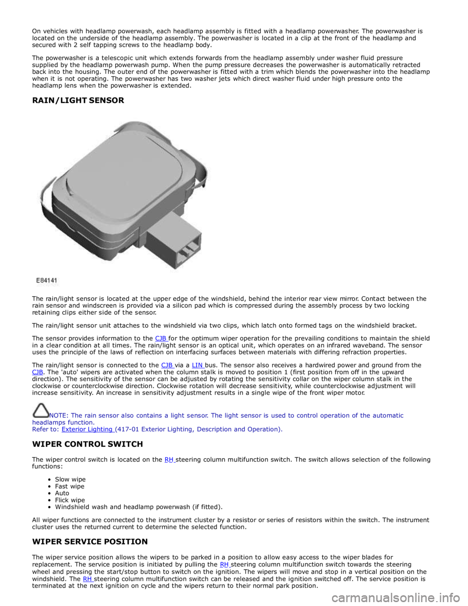
The rain/light sensor is located at the upper edge of the windshield, behind the interior rear view mirror. Contact between the
rain sensor and windscreen is provided via a silicon pad which is compressed during the assembly process by two locking
retaining clips either side of the sensor.
The rain/light sensor unit attaches to the windshield via two clips, which latch onto formed tags on the windshield bracket.
The sensor provides information to the CJB for the optimum wiper operation for the prevailing conditions to maintain the shield in a clear condition at all times. The rain/light sensor is an optical unit, which operates on an infrared waveband. The sensor
uses the principle of the laws of reflection on interfacing surfaces between materials with differing refraction properties.
The rain/light sensor is connected to the CJB via a LIN bus. The sensor also receives a hardwired power and ground from the CJB. The 'auto' wipers are activated when the column stalk is moved to position 1 (first position from off in the upward direction). The sensitivity of the sensor can be adjusted by rotating the sensitivity collar on the wiper column stalk in the
clockwise or counterclockwise direction. Clockwise rotation will decrease sensitivity, while counterclockwise adjustment will
increase sensitivity. An increase in sensitivity adjustment results in a single wipe of the front wiper motor.
NOTE: The rain sensor also contains a light sensor. The light sensor is used to control operation of the automatic
headlamps function.
Refer to: Exterior Lighting (417-01 Exterior Lighting, Description and Operation).
WIPER CONTROL SWITCH
The wiper control switch is located on the RH steering column multifunction switch. The switch allows selection of the following functions:
Slow wipe
Fast wipe
Auto
Flick wipe
Windshield wash and headlamp powerwash (if fitted).
All wiper functions are connected to the instrument cluster by a resistor or series of resistors within the switch. The instrument
cluster uses the returned current to determine the selected function.
WIPER SERVICE POSITION
The wiper service position allows the wipers to be parked in a position to allow easy access to the wiper blades for
replacement. The service position is initiated by pulling the RH steering column multifunction switch towards the steering wheel and pressing the start/stop button to switch on the ignition. The wipers will move and stop in a vertical position on the
windshield. The RH steering column multifunction switch can be released and the ignition switched off. The service position is terminated at the next ignition on cycle and the wipers return to their normal park position.
Page 2544 of 3039
DTC Description Possible Cause Action circuit - short to power
circuit diagrams and check wiper On/Off relay control circuit for
short to power B109514
Wiper On/Off
Relay
Wiper On/Off relay control
circuit - short to ground,
open circuit Refer to the electrical circuit diagrams and check wiper On/Off
relay control circuit for short to ground, open circuit B109612
Wiper High/Low
Relay
Wiper Fast/Slow relay
control circuit - short to
power Carry out any pinpoint tests associated with this DTC using the
manufacturer approved diagnostic system. Refer to the electrical
circuit diagrams and check wiper Fast/Slow relay control circuit for
short to power B109614
Wiper High/Low
Relay
Wiper Fast/Slow relay
control circuit - short to
ground, open circuit Refer to the electrical circuit diagrams and check wiper Fast/Slow
relay control circuit for short to ground, open circuit B10AD09 Rain Sensor
Component failures Carry out any pinpoint tests associated with this DTC using the
manufacturer approved diagnostic system. Suspect the rain/light
sensor, check and install a new sensor as required B10AD11 Rain Sensor
Rain/light sensor power
circuit - short to ground Carry out any pinpoint tests associated with this DTC using the
manufacturer approved diagnostic system. Refer to the electrical
circuit diagrams and check rain/light sensor power circuit for short
to ground B10AD96 Rain Sensor
Component internal
failure Suspect the rain/light sensor, check and install a new sensor as
required B117712
Screenwash
Level Switch
Screenwash level switch
signal circuit - short to
power Refer to the electrical circuit diagrams and check screenwash level
switch signal circuit for short to power B1C4513
Front Wiper Park
Position Switch
Windshield wiper motor
park switch signal circuit -
open circuit Refer to the electrical circuit diagrams and check windshield wiper
motor park switch signal circuit for open circuit B1C4523
Front Wiper Park
Position Switch
Signal stuck low Refer to the electrical circuit diagrams and check front wiper park
position switch input circuit for short, open circuit B1C7812 Powerwash Relay
Powerwash relay control
circuit - short to power Refer to the electrical circuit diagrams and check powerwash relay
control circuit for short to power B1C7814 Powerwash Relay
Powerwash relay control
circuit - short to ground,
open circuit Refer to the electrical circuit diagrams and check powerwash relay
control circuit for short to ground, open circuit B1C7911
Front Washer
Pump
Screenwash pump control
circuit - short to ground Refer to the electrical circuit diagrams and check screenwash
pump control circuit for short to ground B1C7913
Front Washer
Pump
Screenwash pump control
circuit - open circuit Carry out any pinpoint tests associated with this DTC using the
manufacturer approved diagnostic system. Refer to the electrical
circuit diagrams and check screenwash pump control circuit for open circuit www.JagDocs.com
Page 2549 of 3039

Wipers and Washers - Rain Sensor
Removal and Installation
Removal
NOTE: Removal steps in this procedure may contain installation details. Published: 11-May-2011
1. Refer to: Interior Rear View Mirror (501-09 Rear View Mirrors, Removal and Installation).
2.
3.
Installation
1. CAUTIONS:
Make sure that the component is secured in the
retainer.
Make sure that the clips are correctly located.
To install, reverse the removal procedure. www.JagDocs.com