Replace Battery JAGUAR XFR 2010 1.G Repair Manual
[x] Cancel search | Manufacturer: JAGUAR, Model Year: 2010, Model line: XFR, Model: JAGUAR XFR 2010 1.GPages: 3039, PDF Size: 58.49 MB
Page 1869 of 3039
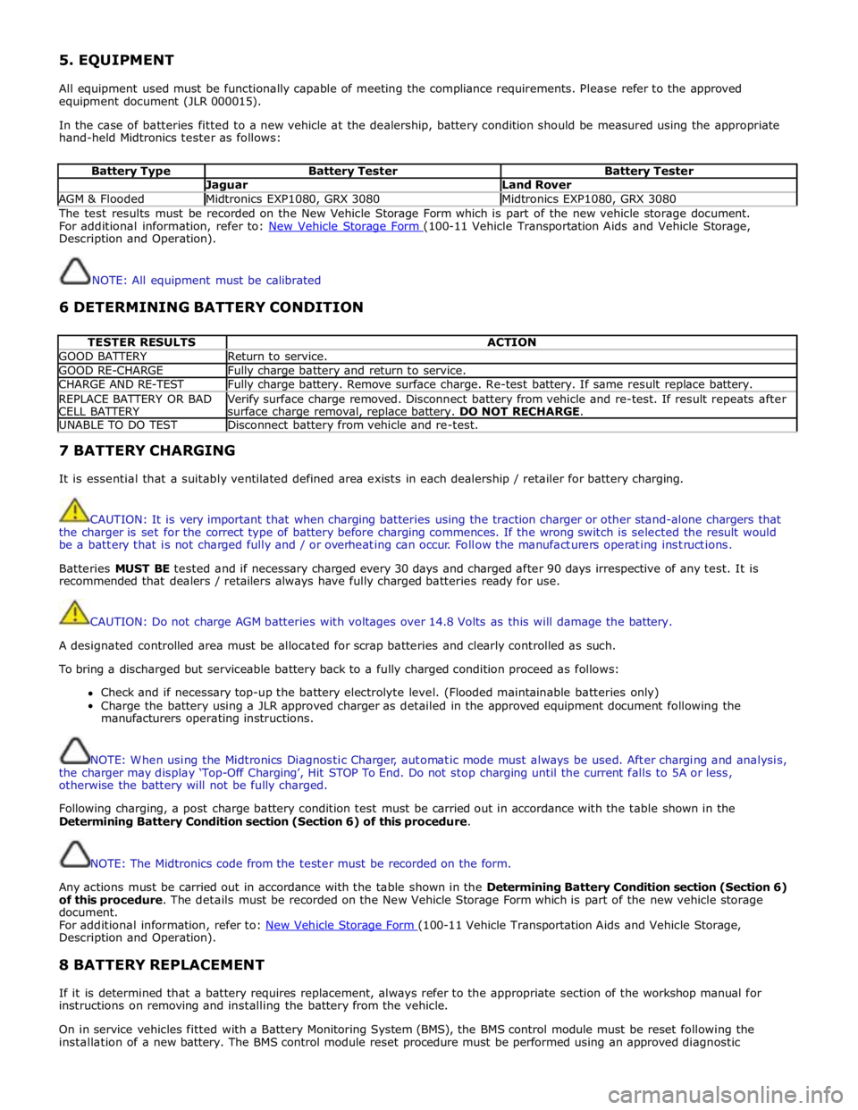
5. EQUIPMENT
All equipment used must be functionally capable of meeting the compliance requirements. Please refer to the approved
equipment document (JLR 000015).
In the case of batteries fitted to a new vehicle at the dealership, battery condition should be measured using the appropriate
hand-held Midtronics tester as follows:
Battery Type Battery Tester Battery Tester Jaguar Land Rover AGM & Flooded Midtronics EXP1080, GRX 3080 Midtronics EXP1080, GRX 3080 The test results must be recorded on the New Vehicle Storage Form which is part of the new vehicle storage document.
For additional information, refer to: New Vehicle Storage Form (100-11 Vehicle Transportation Aids and Vehicle Storage, Description and Operation).
NOTE: All equipment must be calibrated
6 DETERMINING BATTERY CONDITION
TESTER RESULTS ACTION GOOD BATTERY Return to service. GOOD RE-CHARGE Fully charge battery and return to service. CHARGE AND RE-TEST Fully charge battery. Remove surface charge. Re-test battery. If same result replace battery. REPLACE BATTERY OR BAD
CELL BATTERY Verify surface charge removed. Disconnect battery from vehicle and re-test. If result repeats after
surface charge removal, replace battery. DO NOT RECHARGE. UNABLE TO DO TEST Disconnect battery from vehicle and re-test. 7 BATTERY CHARGING
It is essential that a suitably ventilated defined area exists in each dealership / retailer for battery charging.
CAUTION: It is very important that when charging batteries using the traction charger or other stand-alone chargers that
the charger is set for the correct type of battery before charging commences. If the wrong switch is selected the result would
be a battery that is not charged fully and / or overheating can occur. Follow the manufacturers operating instructions.
Batteries MUST BE tested and if necessary charged every 30 days and charged after 90 days irrespective of any test. It is
recommended that dealers / retailers always have fully charged batteries ready for use.
CAUTION: Do not charge AGM batteries with voltages over 14.8 Volts as this will damage the battery.
A designated controlled area must be allocated for scrap batteries and clearly controlled as such.
To bring a discharged but serviceable battery back to a fully charged condition proceed as follows:
Check and if necessary top-up the battery electrolyte level. (Flooded maintainable batteries only)
Charge the battery using a JLR approved charger as detailed in the approved equipment document following the
manufacturers operating instructions.
NOTE: When using the Midtronics Diagnostic Charger, automatic mode must always be used. After charging and analysis,
the charger may display ‘Top-Off Charging’, Hit STOP To End. Do not stop charging until the current falls to 5A or less,
otherwise the battery will not be fully charged.
Following charging, a post charge battery condition test must be carried out in accordance with the table shown in the
Determining Battery Condition section (Section 6) of this procedure.
NOTE: The Midtronics code from the tester must be recorded on the form.
Any actions must be carried out in accordance with the table shown in the Determining Battery Condition section (Section 6)
of this procedure. The details must be recorded on the New Vehicle Storage Form which is part of the new vehicle storage
document.
For additional information, refer to: New Vehicle Storage Form (100-11 Vehicle Transportation Aids and Vehicle Storage, Description and Operation).
8 BATTERY REPLACEMENT
If it is determined that a battery requires replacement, always refer to the appropriate section of the workshop manual for
instructions on removing and installing the battery from the vehicle.
On in service vehicles fitted with a Battery Monitoring System (BMS), the BMS control module must be reset following the
installation of a new battery. The BMS control module reset procedure must be performed using an approved diagnostic
Page 1886 of 3039
the secondary battery (if fitted) and passes through a grommet in the floorpan.
On new vehicles the primary battery positive terminal is fitted with a transit relay. The transit relay must removed using the
correct process detailed in the Pre Delivery Inspection (PDI) manual.
The battery negative terminal is fitted with a BMS control module. The control module is integral with the battery negative
cable and communicates with the GWM via a LIN bus connection. The battery condition information is passed to the GWM
which controls the generator output accordingly.
CAUTION: To avoid damage to the BMS control module, always use the body ground point in the engine compartment and
not the battery negative terminal when connecting a slave power supply.
Failure to use the recommended ground point will lead to the setting of a DTC. Incorrect information of battery condition will
be retained by the BMS control module due to the unmonitored current flow into the battery. The system will however,
recognize and compensate for the change in battery status after a period of time.
If a new battery is fitted, the BMS control module will require re-calibration using a Jaguar approved diagnostic system.
Replacement of the BMS control module requires no action as the control module will re-calibrate automatically.
SECONDARY BATTERY - DUAL BATTERY VEHICLES ONLY
The secondary battery is located in a tray on the next of the primary battery and is secured to the DBJB with a bracket. The
battery negative (-) terminal is connected via a cable to the vehicle body. The positive (+) terminal is connected by a cable to
the DBJB. The battery is vented via a tube which is connected with a T piece to the vent from the primary battery and passes
through a grommet in the floorpan.
The state of charge of the secondary battery is monitored by the Gateway Module (GWM).
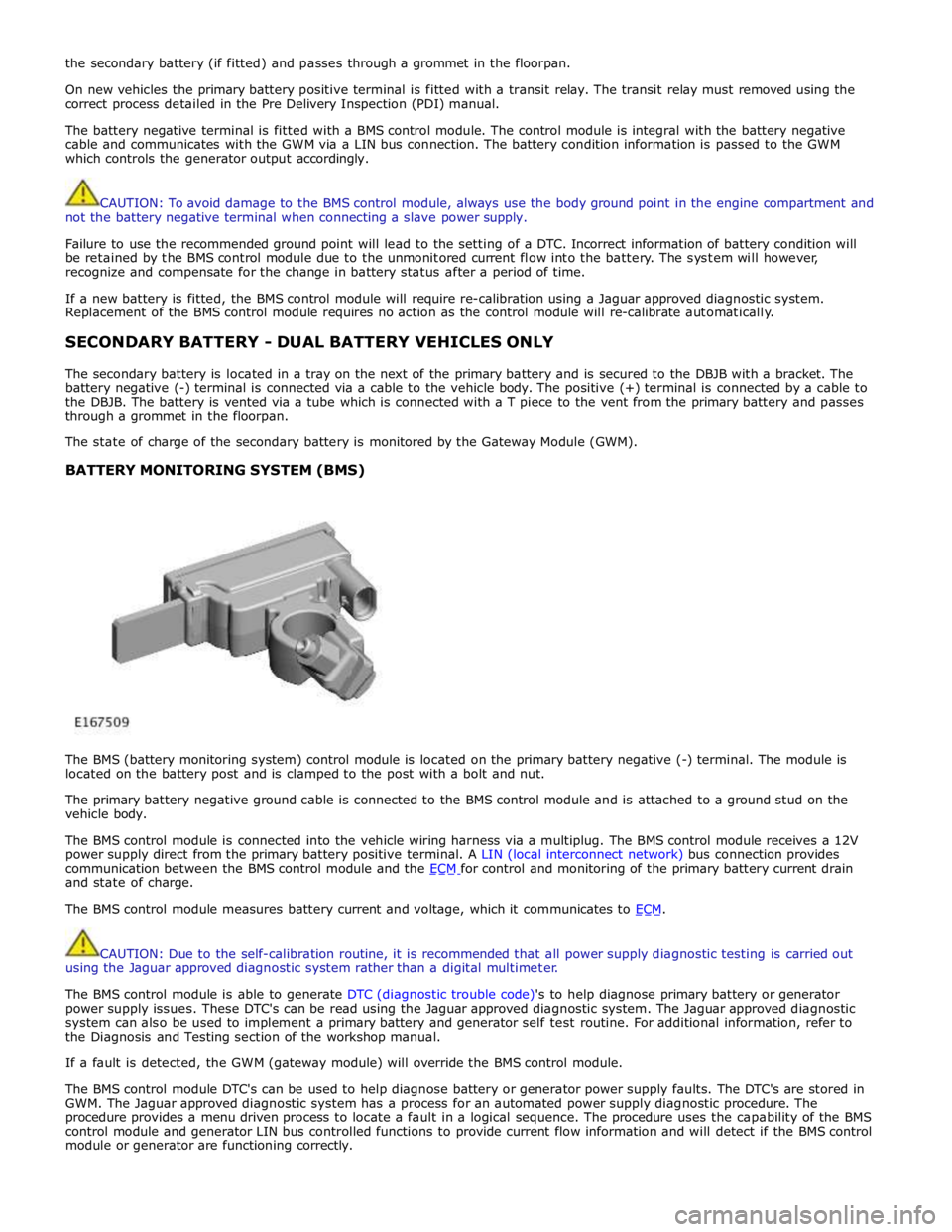
BATTERY MONITORING SYSTEM (BMS)
The BMS (battery monitoring system) control module is located on the primary battery negative (-) terminal. The module is
located on the battery post and is clamped to the post with a bolt and nut.
The primary battery negative ground cable is connected to the BMS control module and is attached to a ground stud on the
vehicle body.
The BMS control module is connected into the vehicle wiring harness via a multiplug. The BMS control module receives a 12V
power supply direct from the primary battery positive terminal. A LIN (local interconnect network) bus connection provides
communication between the BMS control module and the ECM for control and monitoring of the primary battery current drain and state of charge.
The BMS control module measures battery current and voltage, which it communicates to ECM.
CAUTION: Due to the self-calibration routine, it is recommended that all power supply diagnostic testing is carried out
using the Jaguar approved diagnostic system rather than a digital multimeter.
The BMS control module is able to generate DTC (diagnostic trouble code)'s to help diagnose primary battery or generator
power supply issues. These DTC's can be read using the Jaguar approved diagnostic system. The Jaguar approved diagnostic
system can also be used to implement a primary battery and generator self test routine. For additional information, refer to
the Diagnosis and Testing section of the workshop manual.
If a fault is detected, the GWM (gateway module) will override the BMS control module.
The BMS control module DTC's can be used to help diagnose battery or generator power supply faults. The DTC's are stored in
GWM. The Jaguar approved diagnostic system has a process for an automated power supply diagnostic procedure. The
procedure provides a menu driven process to locate a fault in a logical sequence. The procedure uses the capability of the BMS
control module and generator LIN bus controlled functions to provide current flow information and will detect if the BMS control
module or generator are functioning correctly.
Page 1892 of 3039
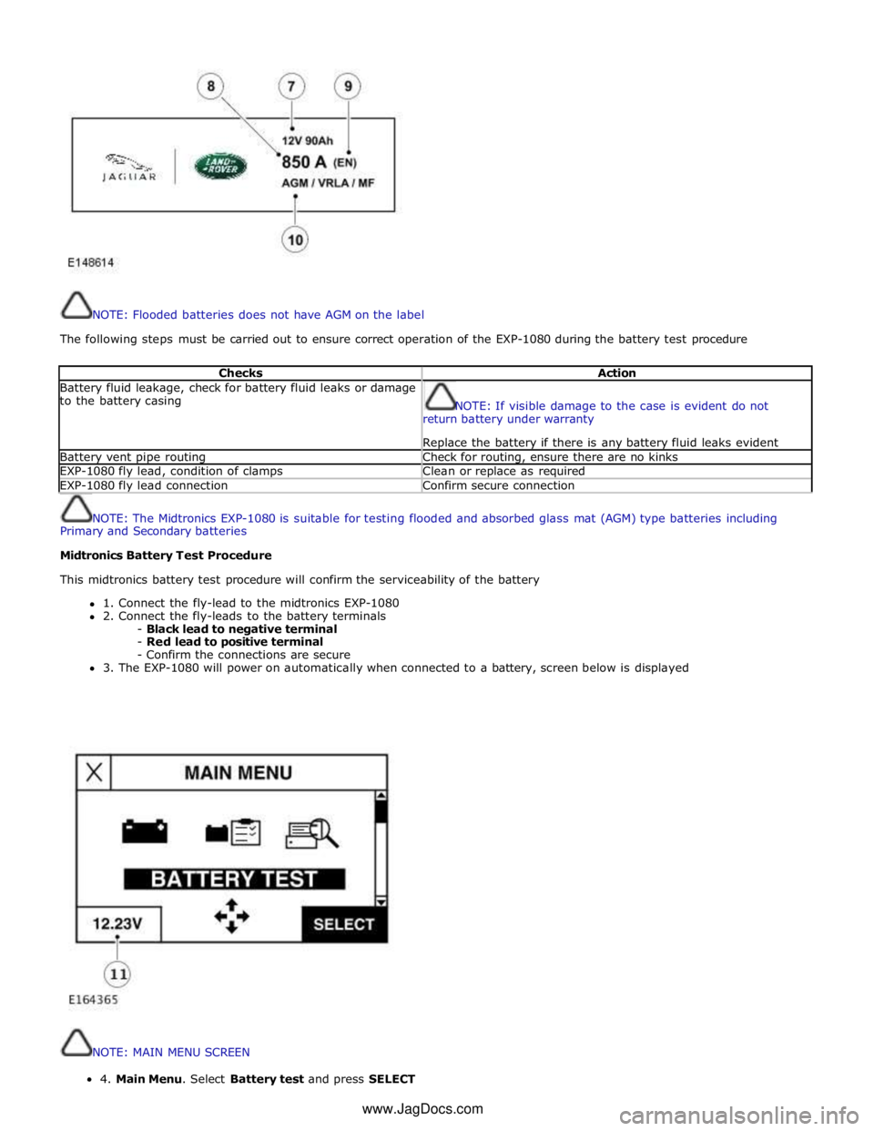
NOTE: Flooded batteries does not have AGM on the label
The following steps must be carried out to ensure correct operation of the EXP-1080 during the battery test procedure
Checks Action Battery fluid leakage, check for battery fluid leaks or damage
to the battery casing
NOTE: If visible damage to the case is evident do not
return battery under warranty
Replace the battery if there is any battery fluid leaks evident Battery vent pipe routing Check for routing, ensure there are no kinks EXP-1080 fly lead, condition of clamps Clean or replace as required EXP-1080 fly lead connection Confirm secure connection
NOTE: The Midtronics EXP-1080 is suitable for testing flooded and absorbed glass mat (AGM) type batteries including
Primary and Secondary batteries
Midtronics Battery Test Procedure
This midtronics battery test procedure will confirm the serviceability of the battery
1. Connect the fly-lead to the midtronics EXP-1080
2. Connect the fly-leads to the battery terminals
- Black lead to negative terminal
- Red lead to positive terminal
- Confirm the connections are secure
3. The EXP-1080 will power on automatically when connected to a battery, screen below is displayed
NOTE: MAIN MENU SCREEN 4.MainMenu.SelectBatterytestandpressSELECT
www.JagDocs.com
Page 1898 of 3039
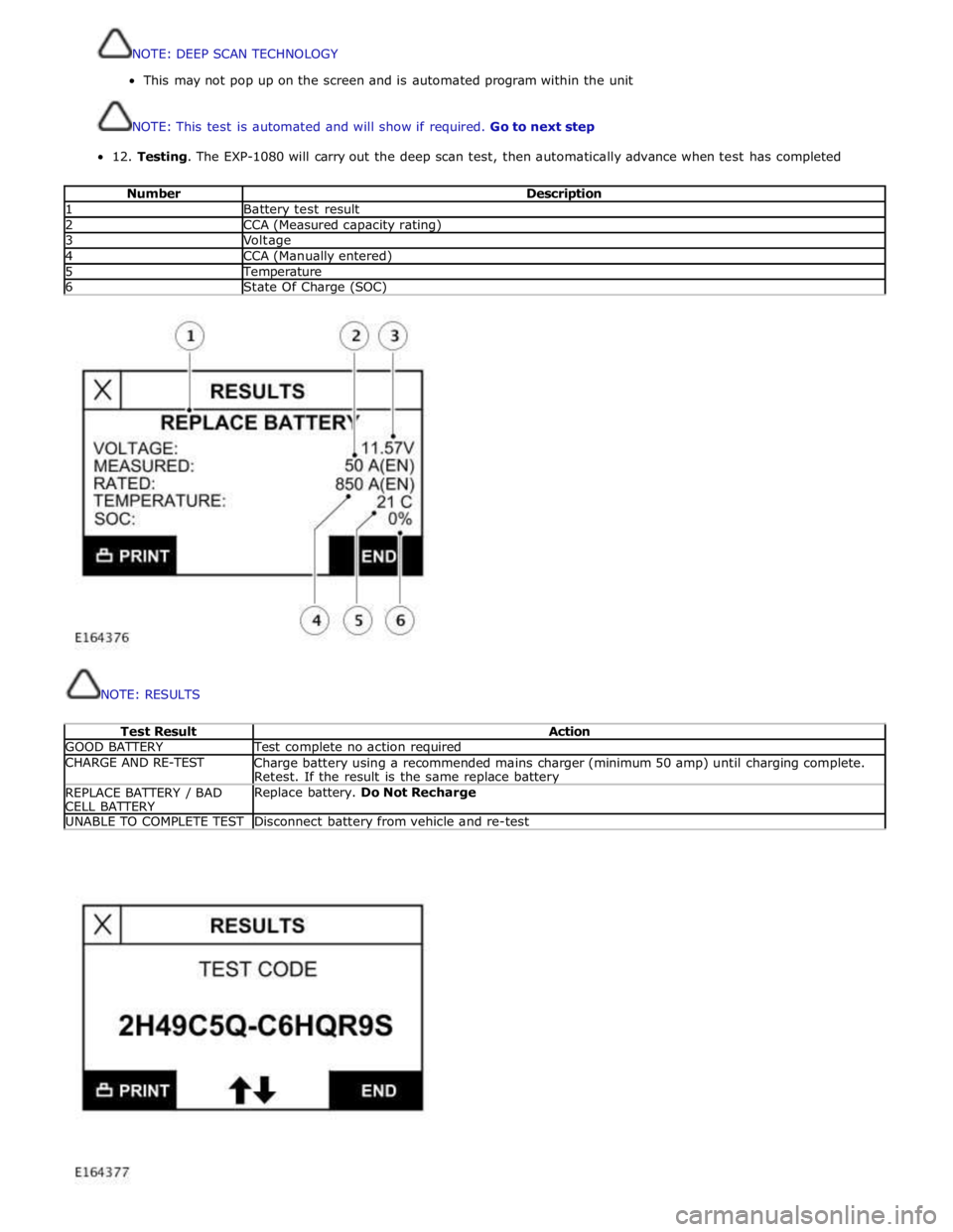
12.
Testing.
The
EXP-1080
will
carry
out
the
deep
scan
test,
then
automatically
advance
when test
has
completed
Number
Description 1
Battery
test
result 2
CCA
(Measured
capacity
rating) 3
Voltage 4
CCA
(Manually
entered) 5
Temperature 6
State
Of
Charge
(SOC)
NOTE:
RESULTS
Test
Result
Action GOOD
BATTERY
Test
complete
no
action required CHARGE
AND RE-TEST
Charge
battery
using a
recommended
mains
charger
(minimum 50 amp)
until
charging
complete.
Retest.
If
the
result
is
the
same replace battery REPLACE
BATTERY
/ BAD
CELL
BATTERY
Replace
battery.
Do
Not
Recharge UNABLE
TO
COMPLETE
TEST
Disconnect
battery
from
vehicle
and re-test
NOTE:DEEPSCANTECHNOLOGY
Thismaynotpop uponthescreen and isautomatedprogramwithin theunit
NOTE:Thistestisautomatedandwillshow ifrequired.Gotonextstep
Page 1899 of 3039
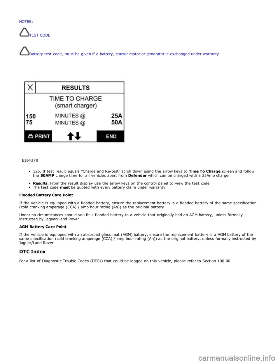
Battery
test
code,
must
be
given if
a
battery,
starter
motor
or
generator
is
exchanged
under
warranty
12b.
If
test
result
equals
"Charge
and
Re-test"
scroll
down
using
the
arrow
keys
to
Time To
Charge
screen and follow
the
50AMP
charge
time
for
all
vehicles
apart
from
Defender
which
can
be
charged
with a
25Amp
charger
Results.
From
the
result
display
use
the
arrow
keys
on
the
control
panel
to
view the
test
code
The
test
code
must
be
quoted
with every
battery
claim
under
warranty
Flooded
Battery
Care
Point
If
the
vehicle
is
equipped with
a
flooded
battery,
ensure
the
replacement
battery
is
a
flooded
battery
of
the
same
specification
(cold
cranking
amperage
(CCA)
/ amp
hour
rating
(Ah))
as
the
original
battery
Under
no
circumstances
should you
fit
a
flooded
battery
to a
vehicle
that
originally
had
an
AGM
battery,
unless
formally
instructed
by Jaguar/Land
Rover
AGM
Battery
Care
Point
If
the
vehicle
is
equipped with
an absorbed
glass
mat
(AGM)
battery,
ensure
the
replacement
battery
is
a
AGM
battery
of
the
same
specification
(cold
cranking
amperage
(CCA)
/
amp
hour
rating
(Ah))
as
the
original
battery,
unless
formally
instructed
by
Jaguar/Land
Rover
DTC
Index
For
a
list
of
Diagnostic
Trouble
Codes
(DTCs)
that
could
be
logged
on
this
vehicle,
please
refer
to
Section
100-00. NOTES:
TESTCODE
Page 2011 of 3039
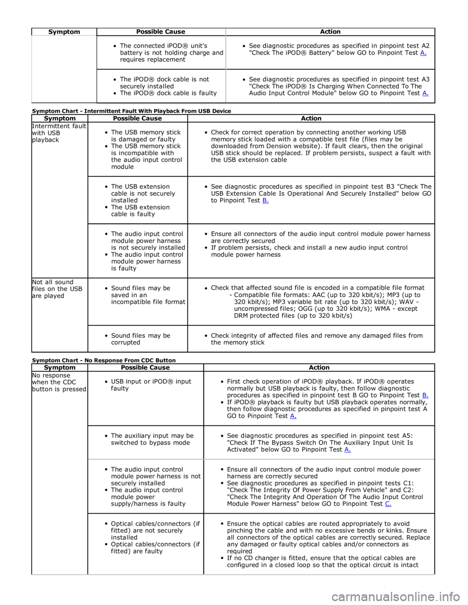
Symptom Possible Cause Action
The connected iPOD® unit's
battery is not holding charge and
requires replacement
See diagnostic procedures as specified in pinpoint test A2
"Check The iPOD® Battery" below GO to Pinpoint Test A.
The iPOD® dock cable is not
securely installed
The iPOD® dock cable is faulty
See diagnostic procedures as specified in pinpoint test A3
"Check The iPOD® Is Charging When Connected To The
Audio Input Control Module" below GO to Pinpoint Test A. Symptom Chart - Intermittent Fault With Playback From USB Device
Symptom Possible Cause Action Intermittent fault
with USB
playback
The USB memory stick
is damaged or faulty
The USB memory stick
is incompatible with
the audio input control
module
Check for correct operation by connecting another working USB
memory stick loaded with a compatible test file (files may be
downloaded from Dension website). If fault clears, then the original
USB stick should be replaced. If problem persists, suspect a fault with
the USB extension cable
The USB extension
cable is not securely
installed
The USB extension
cable is faulty
See diagnostic procedures as specified in pinpoint test B3 "Check The
USB Extension Cable Is Operational And Securely Installed" below GO
to Pinpoint Test B.
The audio input control
module power harness
is not securely installed
The audio input control
module power harness
is faulty
Ensure all connectors of the audio input control module power harness
are correctly secured
If problem persists, check and install a new audio input control
module power harness Not all sound
files on the USB
are played
Sound files may be
saved in an
incompatible file format
Check that affected sound file is encoded in a compatible file format
- Compatible file formats: AAC (up to 320 kbit/s); MP3 (up to
320 kbit/s); MP3 variable bit rate (up to 320 kbit/s); WAV -
uncompressed files; OGG (up to 320 kbit/s); WMA - except
DRM protected files (up to 320 kbit/s)
Sound files may be
corrupted
Check integrity of affected files and remove any damaged files from
the memory stick Symptom Chart - No Response From CDC Button
Symptom Possible Cause Action No response
when the CDC
button is pressed
USB input or iPOD® input
faulty
First check operation of iPOD® playback. If iPOD® operates
normally but USB playback is faulty, then follow diagnostic
procedures as specified in pinpoint test B GO to Pinpoint Test B. If iPOD® playback is faulty but USB playback operates normally,
then follow diagnostic procedures as specified in pinpoint test A
GO to Pinpoint Test A.
The auxiliary input may be
switched to bypass mode
See diagnostic procedures as specified in pinpoint test A5:
"Check If The Bypass Switch On The Auxiliary Input Unit Is
Activated" below GO to Pinpoint Test A.
The audio input control
module power harness is not
securely installed
The audio input control
module power
supply/harness is faulty
Ensure all connectors of the audio input control module power
harness are correctly secured
See diagnostic procedures as specified in pinpoint tests C1:
"Check The Integrity Of Power Supply From Vehicle" and C2:
"Check The Integrity And Operation Of The Audio Input Control
Module Power Harness" below GO to Pinpoint Test C.
Optical cables/connectors (if
fitted) are not securely
installed
Optical cables/connectors (if
fitted) are faulty
Ensure the optical cables are routed appropriately to avoid
pinching the cable and with no excessive bends or kinks. Ensure
all connectors of the optical cables are correctly secured. Replace
any damaged or faulty optical cables and/or connectors as
required
If no CD changer is fitted, ensure that the optical cables are
configured in a closed loop so that the optical circuit is intact
Page 2012 of 3039
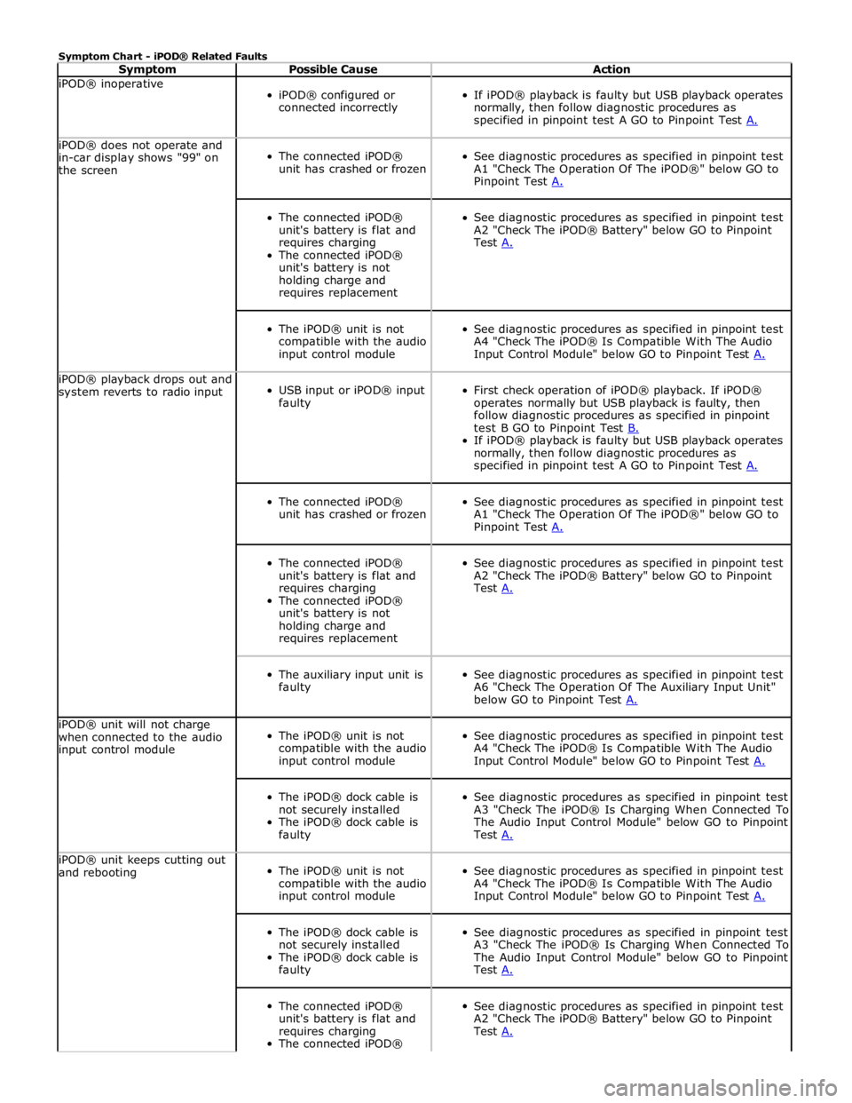
Symptom Chart - iPOD® Related Faults
Symptom Possible Cause Action iPOD® inoperative
iPOD® configured or
connected incorrectly
If iPOD® playback is faulty but USB playback operates
normally, then follow diagnostic procedures as
specified in pinpoint test A GO to Pinpoint Test A. iPOD® does not operate and
in-car display shows "99" on
the screen
The connected iPOD®
unit has crashed or frozen
See diagnostic procedures as specified in pinpoint test
A1 "Check The Operation Of The iPOD®" below GO to
Pinpoint Test A.
The connected iPOD®
unit's battery is flat and
requires charging
The connected iPOD®
unit's battery is not
holding charge and
requires replacement
See diagnostic procedures as specified in pinpoint test
A2 "Check The iPOD® Battery" below GO to Pinpoint
Test A.
The iPOD® unit is not
compatible with the audio
input control module
See diagnostic procedures as specified in pinpoint test
A4 "Check The iPOD® Is Compatible With The Audio
Input Control Module" below GO to Pinpoint Test A. iPOD® playback drops out and
system reverts to radio input
USB input or iPOD® input
faulty
First check operation of iPOD® playback. If iPOD®
operates normally but USB playback is faulty, then
follow diagnostic procedures as specified in pinpoint
test B GO to Pinpoint Test B. If iPOD® playback is faulty but USB playback operates
normally, then follow diagnostic procedures as
specified in pinpoint test A GO to Pinpoint Test A.
The connected iPOD®
unit has crashed or frozen
See diagnostic procedures as specified in pinpoint test
A1 "Check The Operation Of The iPOD®" below GO to
Pinpoint Test A.
The connected iPOD®
unit's battery is flat and
requires charging
The connected iPOD®
unit's battery is not
holding charge and
requires replacement
See diagnostic procedures as specified in pinpoint test
A2 "Check The iPOD® Battery" below GO to Pinpoint
Test A.
The auxiliary input unit is
faulty
See diagnostic procedures as specified in pinpoint test
A6 "Check The Operation Of The Auxiliary Input Unit"
below GO to Pinpoint Test A. iPOD® unit will not charge
when connected to the audio
input control module
The iPOD® unit is not
compatible with the audio
input control module
See diagnostic procedures as specified in pinpoint test
A4 "Check The iPOD® Is Compatible With The Audio
Input Control Module" below GO to Pinpoint Test A.
The iPOD® dock cable is
not securely installed
The iPOD® dock cable is
faulty
See diagnostic procedures as specified in pinpoint test
A3 "Check The iPOD® Is Charging When Connected To
The Audio Input Control Module" below GO to Pinpoint
Test A. iPOD® unit keeps cutting out
and rebooting
The iPOD® unit is not
compatible with the audio
input control module
See diagnostic procedures as specified in pinpoint test
A4 "Check The iPOD® Is Compatible With The Audio
Input Control Module" below GO to Pinpoint Test A.
The iPOD® dock cable is
not securely installed
The iPOD® dock cable is
faulty
See diagnostic procedures as specified in pinpoint test
A3 "Check The iPOD® Is Charging When Connected To
The Audio Input Control Module" below GO to Pinpoint
Test A.
The connected iPOD®
unit's battery is flat and
requires charging
The connected iPOD®
See diagnostic procedures as specified in pinpoint test
A2 "Check The iPOD® Battery" below GO to Pinpoint
Test A.
Page 2013 of 3039
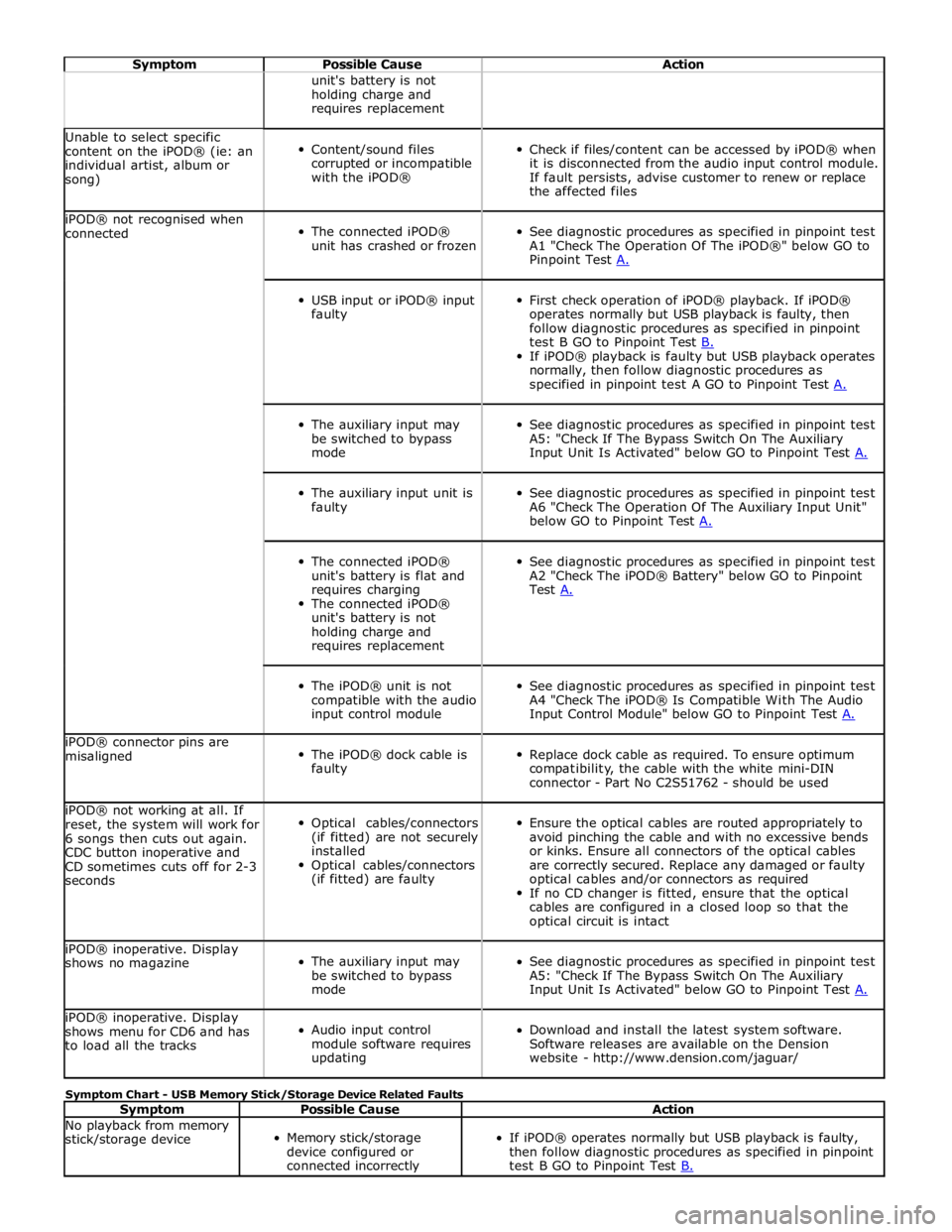
Symptom Possible Cause Action unit's battery is not
holding charge and
requires replacement Unable to select specific
content on the iPOD® (ie: an
individual artist, album or
song)
Content/sound files
corrupted or incompatible
with the iPOD®
Check if files/content can be accessed by iPOD® when
it is disconnected from the audio input control module.
If fault persists, advise customer to renew or replace
the affected files iPOD® not recognised when
connected
The connected iPOD®
unit has crashed or frozen
See diagnostic procedures as specified in pinpoint test
A1 "Check The Operation Of The iPOD®" below GO to
Pinpoint Test A.
USB input or iPOD® input
faulty
First check operation of iPOD® playback. If iPOD®
operates normally but USB playback is faulty, then
follow diagnostic procedures as specified in pinpoint
test B GO to Pinpoint Test B. If iPOD® playback is faulty but USB playback operates
normally, then follow diagnostic procedures as
specified in pinpoint test A GO to Pinpoint Test A.
The auxiliary input may
be switched to bypass
mode
See diagnostic procedures as specified in pinpoint test
A5: "Check If The Bypass Switch On The Auxiliary
Input Unit Is Activated" below GO to Pinpoint Test A.
The auxiliary input unit is
faulty
See diagnostic procedures as specified in pinpoint test
A6 "Check The Operation Of The Auxiliary Input Unit"
below GO to Pinpoint Test A.
The connected iPOD®
unit's battery is flat and
requires charging
The connected iPOD®
unit's battery is not
holding charge and
requires replacement
See diagnostic procedures as specified in pinpoint test
A2 "Check The iPOD® Battery" below GO to Pinpoint
Test A.
The iPOD® unit is not
compatible with the audio
input control module
See diagnostic procedures as specified in pinpoint test
A4 "Check The iPOD® Is Compatible With The Audio
Input Control Module" below GO to Pinpoint Test A. iPOD® connector pins are
misaligned
The iPOD® dock cable is
faulty
Replace dock cable as required. To ensure optimum
compatibility, the cable with the white mini-DIN
connector - Part No C2S51762 - should be used iPOD® not working at all. If
reset, the system will work for
6 songs then cuts out again.
CDC button inoperative and
CD sometimes cuts off for 2-3
seconds
Optical cables/connectors
(if fitted) are not securely
installed
Optical cables/connectors
(if fitted) are faulty
Ensure the optical cables are routed appropriately to
avoid pinching the cable and with no excessive bends
or kinks. Ensure all connectors of the optical cables
are correctly secured. Replace any damaged or faulty
optical cables and/or connectors as required
If no CD changer is fitted, ensure that the optical
cables are configured in a closed loop so that the
optical circuit is intact iPOD® inoperative. Display
shows no magazine
The auxiliary input may
be switched to bypass
mode
See diagnostic procedures as specified in pinpoint test
A5: "Check If The Bypass Switch On The Auxiliary
Input Unit Is Activated" below GO to Pinpoint Test A. iPOD® inoperative. Display
shows menu for CD6 and has
to load all the tracks
Audio input control
module software requires
updating
Download and install the latest system software.
Software releases are available on the Dension
website - http://www.dension.com/jaguar/ Symptom Chart - USB Memory Stick/Storage Device Related Faults
Symptom Possible Cause Action No playback from memory
stick/storage device
Memory stick/storage
device configured or
connected incorrectly
If iPOD® operates normally but USB playback is faulty,
then follow diagnostic procedures as specified in pinpoint
test B GO to Pinpoint Test B.
Page 2014 of 3039
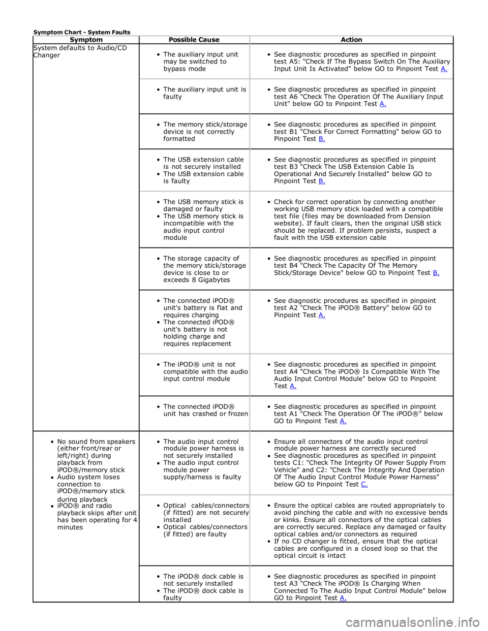
Symptom Chart - System Faults
Symptom Possible Cause Action System defaults to Audio/CD
Changer
The auxiliary input unit
may be switched to
bypass mode
See diagnostic procedures as specified in pinpoint
test A5: "Check If The Bypass Switch On The Auxiliary
Input Unit Is Activated" below GO to Pinpoint Test A.
The auxiliary input unit is
faulty
See diagnostic procedures as specified in pinpoint
test A6 "Check The Operation Of The Auxiliary Input
Unit" below GO to Pinpoint Test A.
The memory stick/storage
device is not correctly
formatted
See diagnostic procedures as specified in pinpoint
test B1 "Check For Correct Formatting" below GO to
Pinpoint Test B.
The USB extension cable
is not securely installed
The USB extension cable
is faulty
See diagnostic procedures as specified in pinpoint
test B3 "Check The USB Extension Cable Is
Operational And Securely Installed" below GO to
Pinpoint Test B.
The USB memory stick is
damaged or faulty
The USB memory stick is
incompatible with the
audio input control
module
Check for correct operation by connecting another
working USB memory stick loaded with a compatible
test file (files may be downloaded from Dension
website). If fault clears, then the original USB stick
should be replaced. If problem persists, suspect a
fault with the USB extension cable
The storage capacity of
the memory stick/storage
device is close to or
exceeds 8 Gigabytes
See diagnostic procedures as specified in pinpoint
test B4 "Check The Capacity Of The Memory
Stick/Storage Device" below GO to Pinpoint Test B.
The connected iPOD®
unit's battery is flat and
requires charging
The connected iPOD®
unit's battery is not
holding charge and
requires replacement
See diagnostic procedures as specified in pinpoint
test A2 "Check The iPOD® Battery" below GO to
Pinpoint Test A.
The iPOD® unit is not
compatible with the audio
input control module
See diagnostic procedures as specified in pinpoint
test A4 "Check The iPOD® Is Compatible With The
Audio Input Control Module" below GO to Pinpoint
Test A.
The connected iPOD®
unit has crashed or frozen
See diagnostic procedures as specified in pinpoint
test A1 "Check The Operation Of The iPOD®" below
GO to Pinpoint Test A.
No sound from speakers
The audio input control
Ensure all connectors of the audio input control (either front/rear or module power harness is module power harness are correctly secured left/right) during not securely installed See diagnostic procedures as specified in pinpoint playback from The audio input control tests C1: "Check The Integrity Of Power Supply From iPOD®/memory stick module power Vehicle" and C2: "Check The Integrity And Operation Audio system loses supply/harness is faulty Of The Audio Input Control Module Power Harness" connection to below GO to Pinpoint Test C. iPOD®/memory stick during playback
Optical cables/connectors
(if fitted) are not securely
installed
Optical cables/connectors
(if fitted) are faulty
Ensure the optical cables are routed appropriately to
avoid pinching the cable and with no excessive bends
or kinks. Ensure all connectors of the optical cables
are correctly secured. Replace any damaged or faulty
optical cables and/or connectors as required
If no CD changer is fitted, ensure that the optical
cables are configured in a closed loop so that the
optical circuit is intact iPOD® and radio playback skips after unit has been operating for 4 minutes
The iPOD® dock cable is
not securely installed
The iPOD® dock cable is
faulty
See diagnostic procedures as specified in pinpoint
test A3 "Check The iPOD® Is Charging When
Connected To The Audio Input Control Module" below
GO to Pinpoint Test A.
Page 2015 of 3039
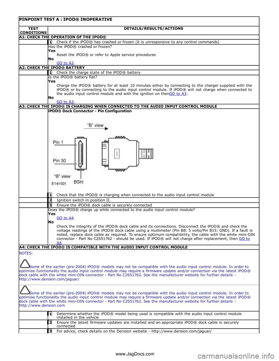
PINPOINT TEST A : IPOD® INOPERATIVE TEST
CONDITIONS DETAILS/RESULTS/ACTIONS A1: CHECK THE OPERATION OF THE IPOD® 1 Check if the iPOD® has crashed or frozen (it is unresponsive to any control commands) Has the iPOD® crashed or frozen?
Yes
Reset the iPOD® or refer to Apple service procedures
No
GO to A2. A2: CHECK THE IPOD® BATTERY 1 Check the charge state of the iPOD® battery Is the iPOD® battery flat?
Yes
Charge the iPOD® battery for at least 10 minutes either by connecting to the charger supplied with the
iPOD® or by connecting to the audio input control module. If iPOD® will not charge when connected to
the audio input control module and with the ignition on thenGO to A3. No
GO to A3. A3: CHECK THE IPOD® IS CHARGING WHEN CONNECTED TO THE AUDIO INPUT CONTROL MODULE iPOD® Dock Connector - Pin Configuration
1 Check that the iPOD® is charging when connected to the audio input control module 2 Ignition switch in position II. 3 Ensure the iPOD® dock cable is securely connected Does the iPOD® charge up while connected to the audio input control module?
Yes
GO to A4. No
Check the integrity of the iPOD® dock cable and its connections. Disconnect the iPOD® and check the
voltage readings of the iPOD® dock cable using a multimeter (Pin B8: 5 volts/Pin B15: GND). If a fault is
noted, replace dock cable as required. To ensure optimum compatibility, the cable with the white mini-DIN
connector - Part No C2S51762 - should be used. If iPOD® will not charge after replacement, then GO to A4. A4: CHECK THE IPOD® IS COMPATIBLE WITH THE AUDIO INPUT CONTROL MODULE NOTES:
Some of the earlier (pre-2004) iPOD® models may not be compatible with the audio input control module. In order to
optimise functionality the audio input control module may require a firmware update and/or connection via the latest iPOD®
dock cable with the white mini-DIN connector - Part No C2S51762. See the manufacturer website for further details -
http://www.dension.com/jaguar/
Some of the earlier (pre-2004) iPOD® models may not be compatible with the audio input control module. In order to
optimise functionality the audio input control module may require a firmware update and/or connection via the latest iPOD®
dock cable with the white mini-DIN connector - Part No C2S51762. See the manufacturer website for further details -
http://www.dension.com 1 Determine whether the iPOD® model being used is compatible with the audio input control module installed in the vehicle 2 Ensure the latest firmware updates are installed and an appropriate iPOD® dock cable is securely connected 3 For advice, check details on the Dension website - http://www.dension.com/jaguar/ www.JagDocs.com