heater JAGUAR XFR 2010 1.G Manual Online
[x] Cancel search | Manufacturer: JAGUAR, Model Year: 2010, Model line: XFR, Model: JAGUAR XFR 2010 1.GPages: 3039, PDF Size: 58.49 MB
Page 2469 of 3039

Instrument Panel and Console - Instrument Panel Console
Removal and Installation Published: 11-May-2011
Removal
CAUTIONS:
Inspect the seals, replace if damaged.
Inspect the O-rings, replace if damaged.
NOTE: Removal steps in this procedure may contain installation details.
All vehicles
1. Refer to: Battery Disconnect and Connect (414-01 Battery, Mounting and Cables, General Procedures).
2. WARNING: Make sure to support the vehicle with axle stands.
Raise and support the vehicle.
Vehicles with supercharger
3. Refer to: Cooling System Draining, Filling and Bleeding - V8 S/C 5.0L Petrol (303-03C Engine Cooling - V8 5.0L Petrol/V8 S/C 5.0L Petrol, General Procedures).
Vehicles without supercharger
4. Refer to: Cooling System Draining, Filling and Bleeding - V8 5.0L Petrol (303-03C Engine Cooling - V8 5.0L Petrol/V8 S/C 5.0L Petrol, General
Procedures).
Vehicles with diesel engine
5. Refer to: Cooling System Draining, Filling and Bleeding (303-03A Engine Cooling - TDV6 3.0L Diesel, General Procedures).
All vehicles
6. Refer to: Air Conditioning (A/C) System Recovery, Evacuation and Charging (412-00 Climate Control System - General Information, General Procedures).
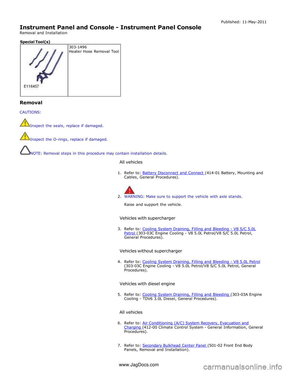
7. Refer to: Secondary Bulkhead Center Panel (501-02 Front End Body Panels, Removal and Installation). 303-1496
Heater Hose Removal Tool Special Tool(s)
www.JagDocs.com
Page 2798 of 3039

Actuation, Removal and Installation).
12. Remove the left-hand and right-hand front seats.
For additional information, refer to: Front Seat (501-10 Seating, Removal and Installation).
13. Remove the heater core and evaporator core housing.
For additional information, refer to: Heater Core and Evaporator Core Housing (412-01 Climate Control, Removal and Installation).
14. Remove the front safety belt retractor.
For additional information, refer to: Front Safety Belt Retractor (501-20A Safety Belt System, Removal and Installation).
15. Remove the B-pillar side impact sensor.
For additional information, refer to: B-Pillar Side Impact Sensor (501-20B Supplemental Restraint System, Removal and Installation).
16. Remove the left-hand and right-hand front floor covering.
17. Remove the rear floor covering.
18. If the left-hand front side member and suspension top mount assembly
is to be repaired, remove the left-hand rear foot well duct.
19. If the right-hand front side member and suspension top mount assembly
is to be repaired, remove the right-hand rear foot well duct.
20. If the drivers side front side member and suspension top mount is being
repaired, remove the pedal box.
21. Release and position the insulating material at the inner bulkhead to
one side.
22. Release and position the inner bulkhead and floor panel wiring harness
to one side.
23. Drain the fuel tank.
For additional information, refer to: Fuel Tank Draining (310-00 Fuel System - General Information, General Procedures).
24. If the left-hand front side member and suspension top mount assembly
is to be repaired, remove the left-hand under shield.
25. If the right-hand front side member and suspension top mount assembly
is to be repaired, remove the right-hand under shield.
26. If the left-hand front side member and suspension top mount assembly
is to be repaired, remove the fuel supply and return pipes.
27. For diesel engine vehicles only, if the left-hand front side member and
suspension top mount assembly is to be repaired, remove the fuel
cooler.
28. If the right-hand front side member and suspension top mount assembly
is to be repaired, release and position the underfloor wiring harness to
Page 2857 of 3039

Panel Sheet Metal Repairs, Removal and Installation).
7. Remove the side air curtain module.
For additional information, refer to: Side Air Curtain Module (501-20B Supplemental Restraint System, Removal and Installation).
8. Remove the front seat.
For additional information, refer to: Front Seat (501-10 Seating, Removal and Installation).
9. Remove the floor covering.
10. If the passenger side A-pillar reinforcement is to be repaired, remove
the heater core and evaporator core housing.
For additional information, refer to: Heater Core and Evaporator Core Housing (412-01 Climate Control, Removal and Installation).
11. If the right-hand A-pillar reinforcement is to be repaired, remove the
central junction box.
For additional information, refer to: Central Junction Box (CJB) (418-00 Module Communications Network, Removal and Installation).
12. If the drivers side A-pillar reinforcement is to be repaired, remove the
pedal box.
13. Release and lay aside the insulating material at the inner bulkhead.
14. Release and position aside the inner bulkhead and floor panel wiring
harness.
15. NOTE: The NVH components may have already been
removed on the outer panel.
Remove the upper and lower NVH components and if
undamaged retain for reuse.