2000 JAGUAR XFR 2010 1.G Workshop Manual
[x] Cancel search | Manufacturer: JAGUAR, Model Year: 2010, Model line: XFR, Model: JAGUAR XFR 2010 1.GPages: 3039, PDF Size: 58.49 MB
Page 163 of 3039

DTC Description Possible Causes Action supply circuits to the Park Brake Module. Repair
wiring as required, clear the DTC and retest the
system U3006-16
Control Module Input
Power A - Circuit
voltage below threshold
ECU logic voltage is high
(over 18 volts for 40mS)
Wiring harness fault
Charging system fault
Refer to electrical circuit diagrams, check power
supplies and ground connections to the park brake
control module. Check battery voltage and
charging system. Repair wiring harness or
charging system as required, clear DTC, perform
battery reset. Retest system U3006-17
Control Module Input
Power A - Circuit
voltage above threshold
ECU logic voltage is low
(below 8 volts for 2000mS)
Wiring harness fault
Charging system fault
Refer to electrical circuit diagrams, check power
supplies and ground connections to the park brake
control module. Check battery voltage and
charging system. Repair wiring harness or
charging system as required, clear DTC, perform
battery reset. Retest system U3007-14
Control Module Input
Power B - Circuit short
to ground or open
Connector fault - bent,
loose or corroded pin(s)
Harness fault
Refer to electrical circuit diagrams, check Park
Brake Module high power feed circuit for open
circuits or short to ground. Repair wiring harness
as required, clear DTC
Page 586 of 3039
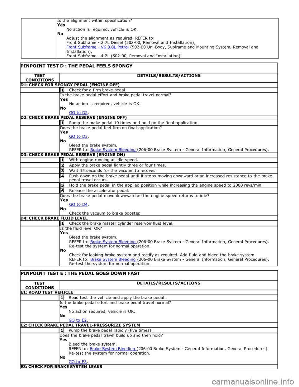
TEST
CONDITIONS DETAILS/RESULTS/ACTIONS D1: CHECK FOR SPONGY PEDAL (ENGINE OFF) 1 Check for a firm brake pedal. Is the brake pedal effort and brake pedal travel normal? Yes
No action is required, vehicle is OK.
No
GO to D2. D2: CHECK BRAKE PEDAL RESERVE (ENGINE OFF) 1 Pump the brake pedal 10 times and hold on the final application. Does the brake pedal feel firm on final application? Yes
GO to D3. No
Bleed the brake system.
REFER to: Brake System Bleeding (206-00 Brake System - General Information, General Procedures). D3: CHECK BRAKE PEDAL RESERVE (ENGINE ON) 1 With engine running at idle speed. 2 Apply the brake pedal lightly three or four times. 3 Wait 15 seconds for the vacuum to recover. 4 Push down on the brake pedal until it stops moving downward or an increased resistance to the brake pedal travel occurs. 5 Hold the brake pedal in the applied position while increasing the engine speed to 2000 revs/min. 6 Release the accelerator pedal. Does the brake pedal move downward as the engine speed returns to idle? Yes
GO to D4. No
Check the vacuum to brake booster. D4: CHECK BRAKE FLUID LEVEL 1 Check the brake master cylinder reservoir fluid level. Is the fluid level OK? Yes
Bleed the brake system.
REFER to: Brake System Bleeding (206-00 Brake System - General Information, General Procedures). Re-test the system for normal operation.
No
Check for leaking brake system and rectify as required. Add fluid and bleed the brake system.
REFER to: Brake System Bleeding (206-00 Brake System - General Information, General Procedures). Re-test the system for normal operation.
PINPOINT TEST E : THE PEDAL GOES DOWN FAST TEST
CONDITIONS DETAILS/RESULTS/ACTIONS E1: ROAD TEST VEHICLE 1 Road test the vehicle and apply the brake pedal. Is the brake pedal effort and brake pedal travel normal? Yes
No action required, vehicle is OK.
No
GO to E2. E2: CHECK BRAKE PEDAL TRAVEL-PRESSURIZE SYSTEM 1 Pump the brake pedal rapidly (five times). Does the brake pedal travel build up and then hold? Yes
Bleed the brake system.
REFER to: Brake System Bleeding (206-00 Brake System - General Information, General Procedures). Re-test the system for normal operation.
No
GO to E3. E3: CHECK FOR BRAKE SYSTEM LEAKS Is the alignment within specification?
Yes
No action is required, vehicle is OK.
No
Adjust the alignment as required. REFER to:
Front Subframe - 2.7L Diesel (502-00, Removal and Installation),
Front Subframe - V6 3.0L Petrol (502-00 Uni-Body, Subframe and Mounting System, Removal and Installation),
Front Subframe - 4.2L (502-00, Removal and Installation).
Page 589 of 3039
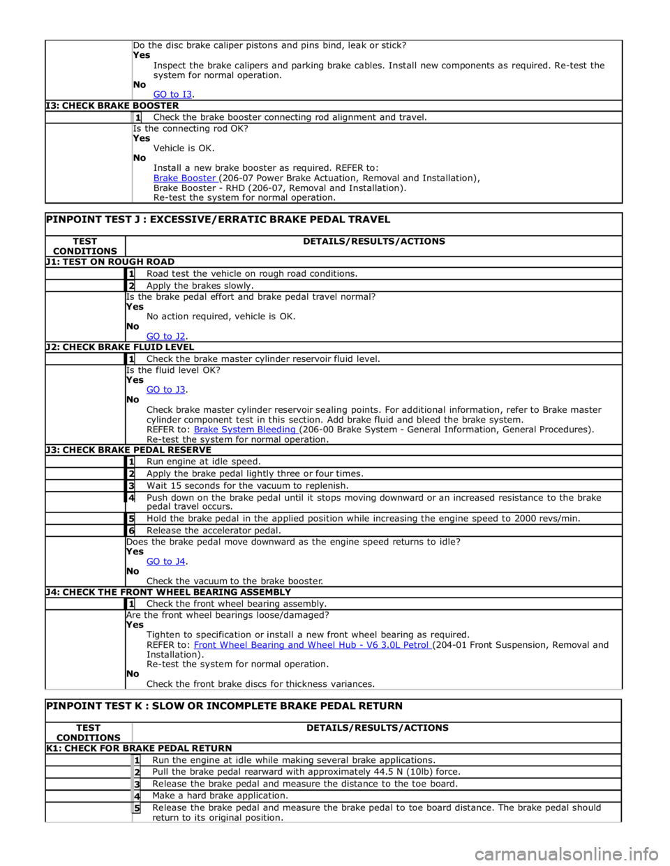
Yes
Inspect the brake calipers and parking brake cables. Install new components as required. Re-test the
system for normal operation.
No
GO to I3. I3: CHECK BRAKE BOOSTER 1 Check the brake booster connecting rod alignment and travel. Is the connecting rod OK? Yes
Vehicle is OK.
No
Install a new brake booster as required. REFER to:
Brake Booster (206-07 Power Brake Actuation, Removal and Installation), Brake Booster - RHD (206-07, Removal and Installation).
Re-test the system for normal operation.
PINPOINT TEST J : EXCESSIVE/ERRATIC BRAKE PEDAL TRAVEL TEST
CONDITIONS DETAILS/RESULTS/ACTIONS J1: TEST ON ROUGH ROAD 1 Road test the vehicle on rough road conditions. 2 Apply the brakes slowly. Is the brake pedal effort and brake pedal travel normal?
Yes
No action required, vehicle is OK.
No
GO to J2. J2: CHECK BRAKE FLUID LEVEL 1 Check the brake master cylinder reservoir fluid level. Is the fluid level OK?
Yes
GO to J3. No
Check brake master cylinder reservoir sealing points. For additional information, refer to Brake master
cylinder component test in this section. Add brake fluid and bleed the brake system.
REFER to: Brake System Bleeding (206-00 Brake System - General Information, General Procedures). Re-test the system for normal operation. J3: CHECK BRAKE PEDAL RESERVE 1 Run engine at idle speed. 2 Apply the brake pedal lightly three or four times. 3 Wait 15 seconds for the vacuum to replenish. 4 Push down on the brake pedal until it stops moving downward or an increased resistance to the brake pedal travel occurs. 5 Hold the brake pedal in the applied position while increasing the engine speed to 2000 revs/min. 6 Release the accelerator pedal. Does the brake pedal move downward as the engine speed returns to idle?
Yes
GO to J4. No
Check the vacuum to the brake booster. J4: CHECK THE FRONT WHEEL BEARING ASSEMBLY 1 Check the front wheel bearing assembly. Are the front wheel bearings loose/damaged?
Yes
Tighten to specification or install a new front wheel bearing as required.
REFER to: Front Wheel Bearing and Wheel Hub - V6 3.0L Petrol (204-01 Front Suspension, Removal and Installation).
Re-test the system for normal operation.
No
Check the front brake discs for thickness variances.
PINPOINT TEST K : SLOW OR INCOMPLETE BRAKE PEDAL RETURN TEST
CONDITIONS DETAILS/RESULTS/ACTIONS K1: CHECK FOR BRAKE PEDAL RETURN 1 Run the engine at idle while making several brake applications. 2 Pull the brake pedal rearward with approximately 44.5 N (10lb) force. 3 Release the brake pedal and measure the distance to the toe board. 4 Make a hard brake application. 5 Release the brake pedal and measure the brake pedal to toe board distance. The brake pedal should return to its original position.
Page 1129 of 3039
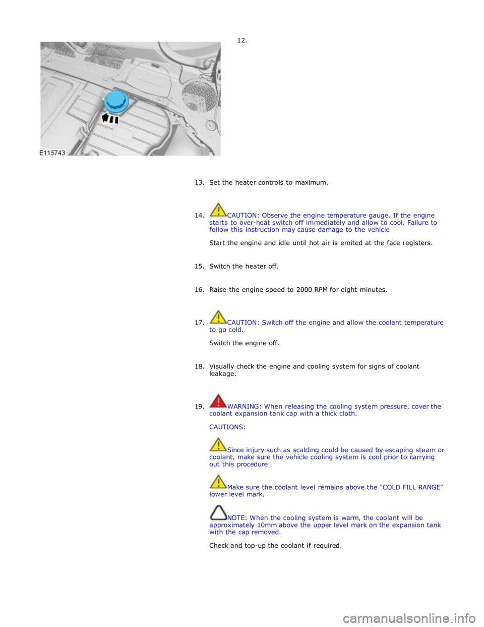
12.
13.
Set the heater controls to maximum.
14. CAUTION: Observe the engine temperature gauge. If the engine
starts to over-heat switch off immediately and allow to cool. Failure to
follow this instruction may cause damage to the vehicle
Start the engine and idle until hot air is emited at the face registers.
15. Switch the heater off.
16. Raise the engine speed to 2000 RPM for eight minutes.
17. CAUTION: Switch off the engine and allow the coolant temperature
to go cold.
Switch the engine off.
18. Visually check the engine and cooling system for signs of coolant
leakage.
19. WARNING: When releasing the cooling system pressure, cover the
coolant expansion tank cap with a thick cloth.
CAUTIONS:
Since injury such as scalding could be caused by escaping steam or
coolant, make sure the vehicle cooling system is cool prior to carrying
out this procedure
Make sure the coolant level remains above the "COLD FILL RANGE"
lower level mark.
NOTE: When the cooling system is warm, the coolant will be
approximately 10mm above the upper level mark on the expansion tank
with the cap removed.
Check and top-up the coolant if required.
Page 1132 of 3039
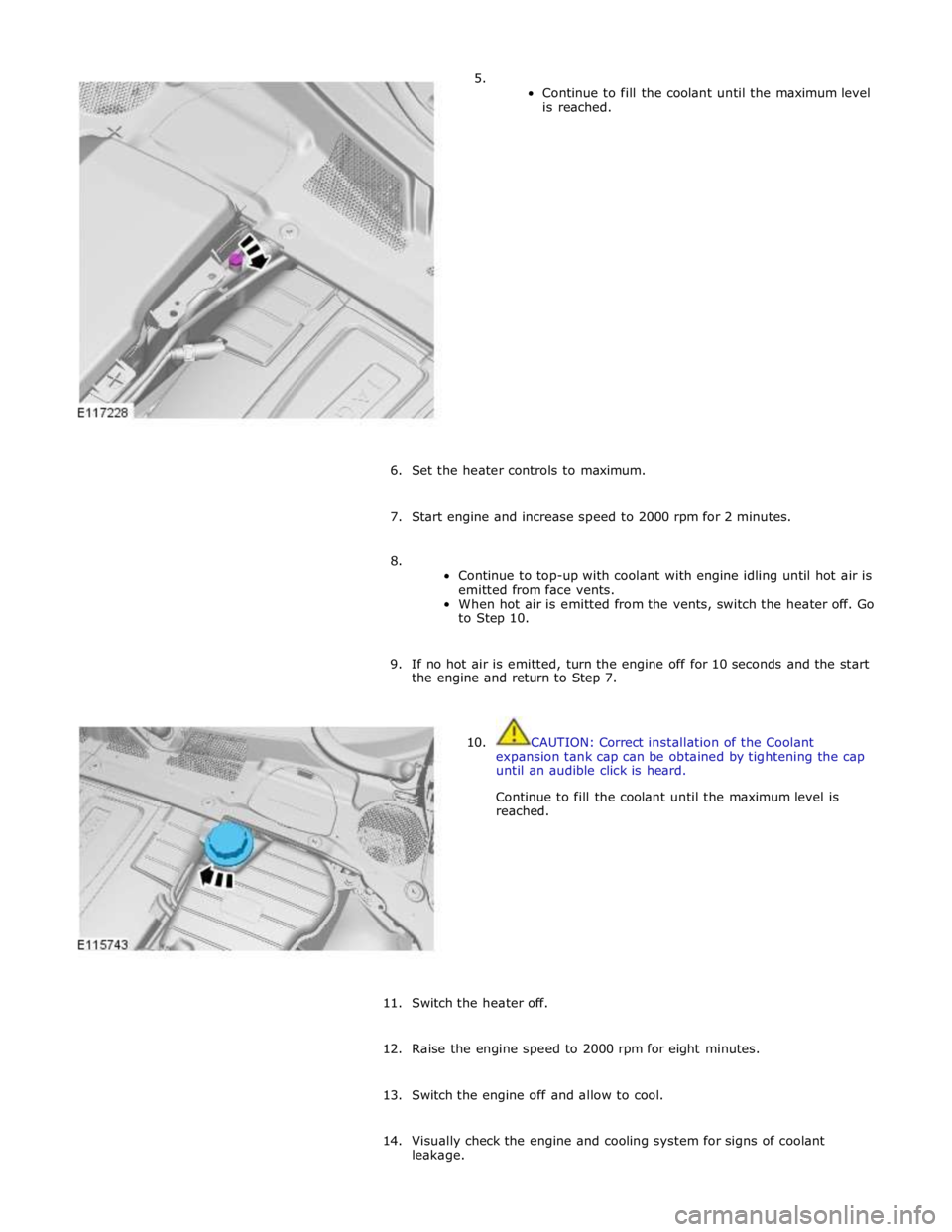
5.
Continue to fill the coolant until the maximum level
is reached.
6. Set the heater controls to maximum.
7. Start engine and increase speed to 2000 rpm for 2 minutes.
8.
Continue to top-up with coolant with engine idling until hot air is
emitted from face vents.
When hot air is emitted from the vents, switch the heater off. Go
to Step 10.
9. If no hot air is emitted, turn the engine off for 10 seconds and the start
the engine and return to Step 7.
10. CAUTION: Correct installation of the Coolant
expansion tank cap can be obtained by tightening the cap
until an audible click is heard.
Continue to fill the coolant until the maximum level is
reached.
11. Switch the heater off.
12. Raise the engine speed to 2000 rpm for eight minutes.
13. Switch the engine off and allow to cool.
14. Visually check the engine and cooling system for signs of coolant
leakage.
Page 1138 of 3039
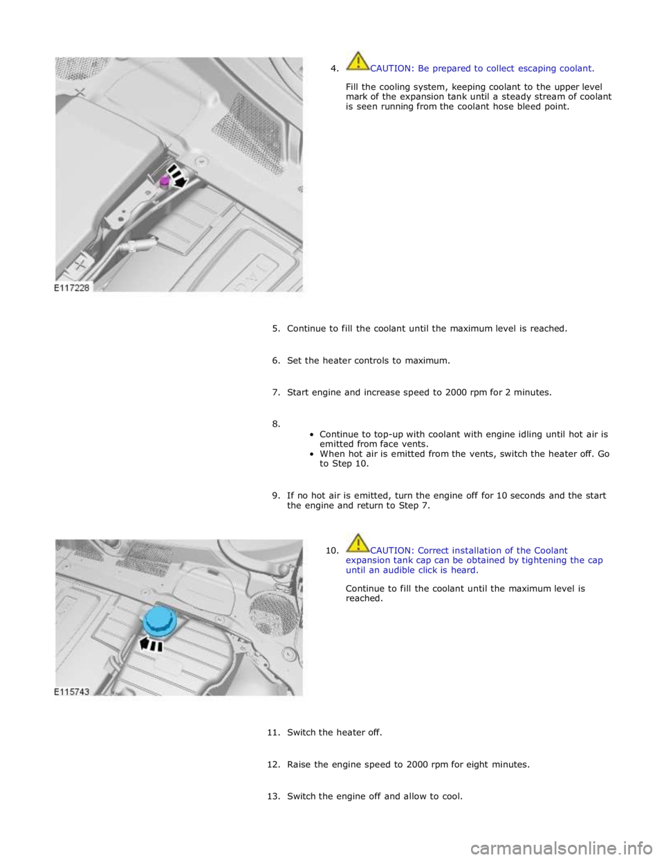
4. CAUTION: Be prepared to collect escaping coolant.
Fill the cooling system, keeping coolant to the upper level
mark of the expansion tank until a steady stream of coolant
is seen running from the coolant hose bleed point.
5. Continue to fill the coolant until the maximum level is reached.
6. Set the heater controls to maximum.
7. Start engine and increase speed to 2000 rpm for 2 minutes.
8.
Continue to top-up with coolant with engine idling until hot air is
emitted from face vents.
When hot air is emitted from the vents, switch the heater off. Go
to Step 10.
9. If no hot air is emitted, turn the engine off for 10 seconds and the start
the engine and return to Step 7.
10. CAUTION: Correct installation of the Coolant
expansion tank cap can be obtained by tightening the cap
until an audible click is heard.
Continue to fill the coolant until the maximum level is
reached.
11. Switch the heater off.
12. Raise the engine speed to 2000 rpm for eight minutes.
13. Switch the engine off and allow to cool.
Page 1365 of 3039
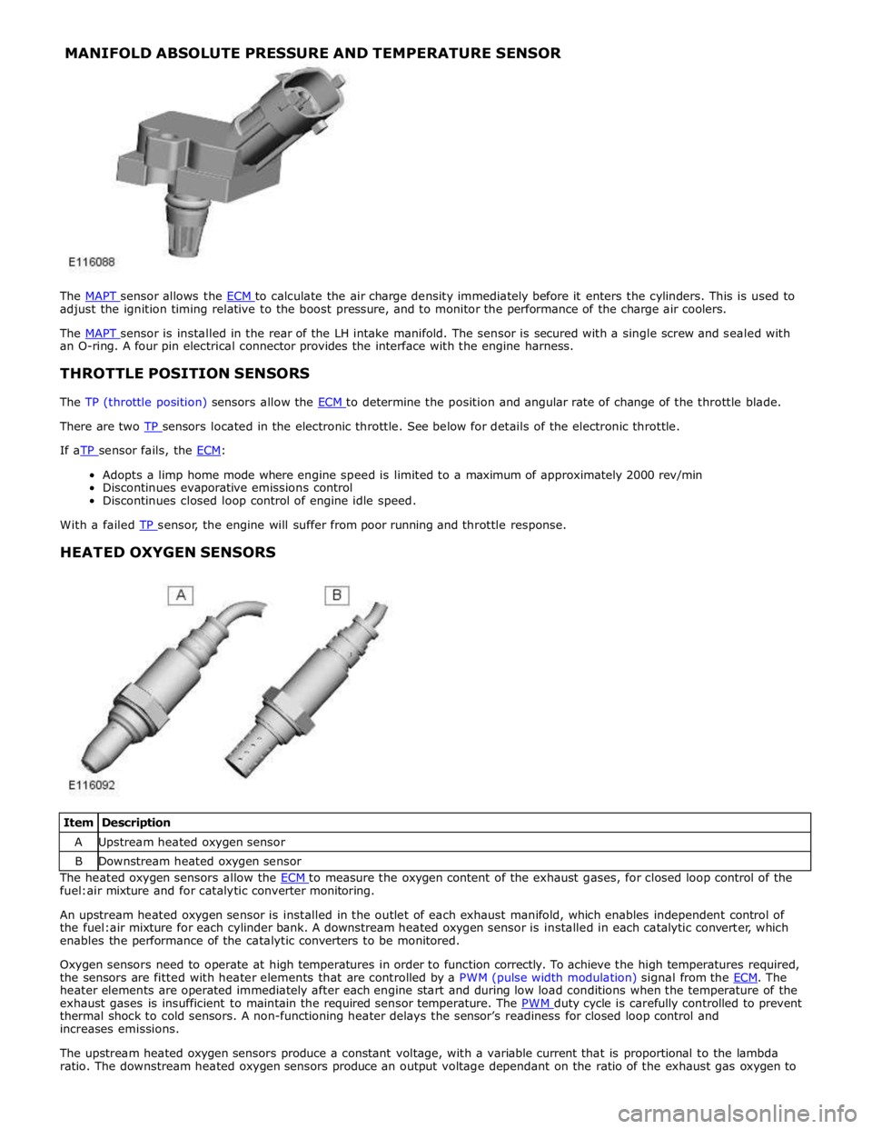
MANIFOLD ABSOLUTE PRESSURE AND TEMPERATURE SENSOR
The MAPT sensor allows the ECM to calculate the air charge density immediately before it enters the cylinders. This is used to adjust the ignition timing relative to the boost pressure, and to monitor the performance of the charge air coolers.
The MAPT sensor is installed in the rear of the LH intake manifold. The sensor is secured with a single screw and sealed with an O-ring. A four pin electrical connector provides the interface with the engine harness.
THROTTLE POSITION SENSORS
The TP (throttle position) sensors allow the ECM to determine the position and angular rate of change of the throttle blade. There are two TP sensors located in the electronic throttle. See below for details of the electronic throttle. If aTP sensor fails, the ECM:
Adopts a limp home mode where engine speed is limited to a maximum of approximately 2000 rev/min
Discontinues evaporative emissions control
Discontinues closed loop control of engine idle speed.
With a failed TP sensor, the engine will suffer from poor running and throttle response.
HEATED OXYGEN SENSORS
Item Description A Upstream heated oxygen sensor B Downstream heated oxygen sensor The heated oxygen sensors allow the ECM to measure the oxygen content of the exhaust gases, for closed loop control of the fuel:air mixture and for catalytic converter monitoring.
An upstream heated oxygen sensor is installed in the outlet of each exhaust manifold, which enables independent control of
the fuel:air mixture for each cylinder bank. A downstream heated oxygen sensor is installed in each catalytic converter, which
enables the performance of the catalytic converters to be monitored.
Oxygen sensors need to operate at high temperatures in order to function correctly. To achieve the high temperatures required,
the sensors are fitted with heater elements that are controlled by a PWM (pulse width modulation) signal from the ECM. The heater elements are operated immediately after each engine start and during low load conditions when the temperature of the
exhaust gases is insufficient to maintain the required sensor temperature. The PWM duty cycle is carefully controlled to prevent thermal shock to cold sensors. A non-functioning heater delays the sensor’s readiness for closed loop control and
increases emissions.
The upstream heated oxygen sensors produce a constant voltage, with a variable current that is proportional to the lambda
ratio. The downstream heated oxygen sensors produce an output voltage dependant on the ratio of the exhaust gas oxygen to
Page 1366 of 3039
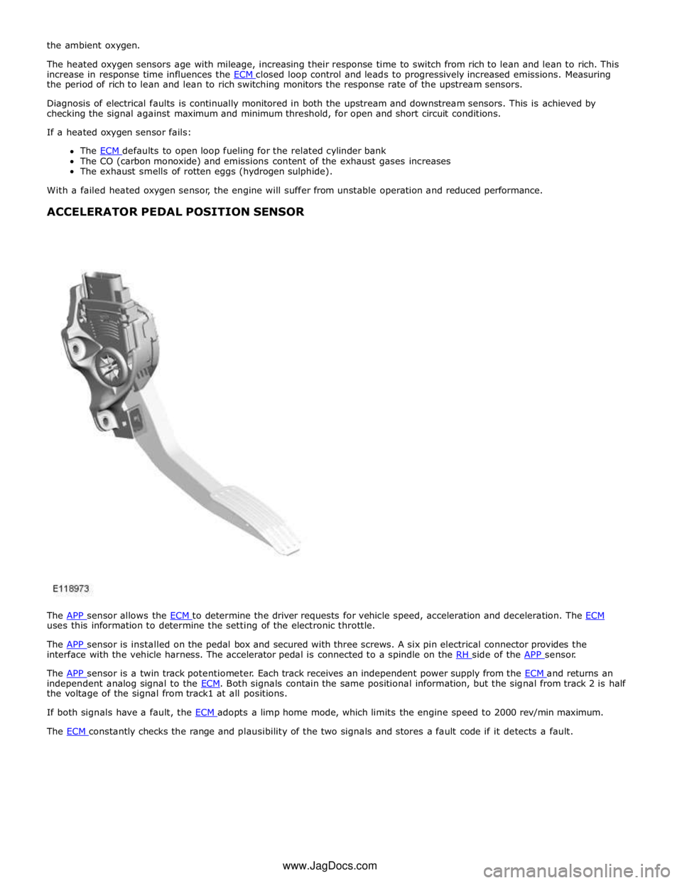
the period of rich to lean and lean to rich switching monitors the response rate of the upstream sensors.
Diagnosis of electrical faults is continually monitored in both the upstream and downstream sensors. This is achieved by
checking the signal against maximum and minimum threshold, for open and short circuit conditions.
If a heated oxygen sensor fails:
The ECM defaults to open loop fueling for the related cylinder bank The CO (carbon monoxide) and emissions content of the exhaust gases increases
The exhaust smells of rotten eggs (hydrogen sulphide).
With a failed heated oxygen sensor, the engine will suffer from unstable operation and reduced performance.
ACCELERATOR PEDAL POSITION SENSOR
The APP sensor allows the ECM to determine the driver requests for vehicle speed, acceleration and deceleration. The ECM uses this information to determine the setting of the electronic throttle.
The APP sensor is installed on the pedal box and secured with three screws. A six pin electrical connector provides the interface with the vehicle harness. The accelerator pedal is connected to a spindle on the RH side of the APP sensor.
The APP sensor is a twin track potentiometer. Each track receives an independent power supply from the ECM and returns an independent analog signal to the ECM. Both signals contain the same positional information, but the signal from track 2 is half the voltage of the signal from track1 at all positions.
If both signals have a fault, the ECM adopts a limp home mode, which limits the engine speed to 2000 rev/min maximum. The ECM constantly checks the range and plausibility of the two signals and stores a fault code if it detects a fault. www.JagDocs.com
Page 1487 of 3039
30. CAUTION: Observe the engine temperature warning light. If the
warning light is displayed, switch off immediately and allow to cool.
Failure to follow this instruction may cause damage to the vehicle.
Raise the engine speed to 2000 RPM and maintain at 2000 RPM until the
engine cooling fan operates.
31. CAUTION: Switch off the engine and allow the coolant temperature
to go cold.
Switch the engine off and allow to cool.
32. Visually check the engine and cooling system for signs of coolant
leakage.
33. WARNINGS:
When releasing the cooling system pressure, cover the coolant
expansion tank cap with a thick cloth.
Since injury such as scalding could be caused by escaping steam or
coolant, make sure the vehicle cooling system is cool prior to carrying
out this procedure.
CAUTIONS:
Make sure the coolant level remains above the "COLD FILL RANGE"
lower level mark.
Anti-freeze concentration must be maintained at 50%.
NOTE: When the cooling system is warm, the coolant will be
approximately 10mm above the upper level mark on the expansion tank
with the cap removed.
Check and top-up the coolant if required.
34. Refer to: Transmission Fluid Level Check (307-01B Automatic Transmission/Transaxle - TDV6 3.0L Diesel /V8 5.0L Petrol/V8 S/C 5.0L
Petrol, General Procedures).
Page 1503 of 3039
28. CAUTION: Observe the engine temperature warning light. If the
warning light is displayed, switch off immediately and allow to cool.
Failure to follow this instruction may cause damage to the vehicle.
Raise the engine speed to 2000 RPM and maintain at 2000 RPM until the
engine cooling fan operates.
29. CAUTION: Switch off the engine and allow the coolant temperature
to go cold.
Switch the engine off and allow to cool.
30. Visually check the engine and cooling system for signs of coolant
leakage.
31. WARNINGS:
When releasing the cooling system pressure, cover the coolant
expansion tank cap with a thick cloth.
Since injury such as scalding could be caused by escaping steam or
coolant, make sure the vehicle cooling system is cool prior to carrying
out this procedure.
CAUTIONS:
Make sure the coolant level remains above the "COLD FILL RANGE"
lower level mark.
Anti-freeze concentration must be maintained at 50%.
NOTE: When the cooling system is warm, the coolant will be
approximately 10mm above the upper level mark on the expansion tank
with the cap removed.
Check and top-up the coolant if required.
32. Refer to: Transmission Fluid Level Check (307-01B Automatic Transmission/Transaxle - TDV6 3.0L Diesel /V8 5.0L Petrol/V8 S/C 5.0L
Petrol, General Procedures).