tow JAGUAR XFR 2010 1.G Workshop Manual
[x] Cancel search | Manufacturer: JAGUAR, Model Year: 2010, Model line: XFR, Model: JAGUAR XFR 2010 1.GPages: 3039, PDF Size: 58.49 MB
Page 33 of 3039
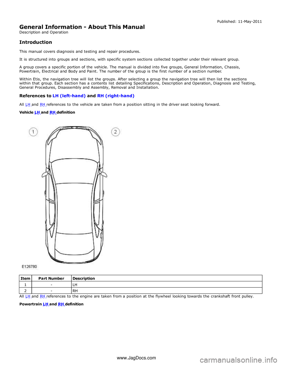
Vehicle LH and RH definition
Item Part Number Description 1 - LH 2 - RH All LH and RH references to the engine are taken from a position at the flywheel looking towards the crankshaft front pulley.
Powertrain LH and RH definition
www.JagDocs.com
Page 75 of 3039
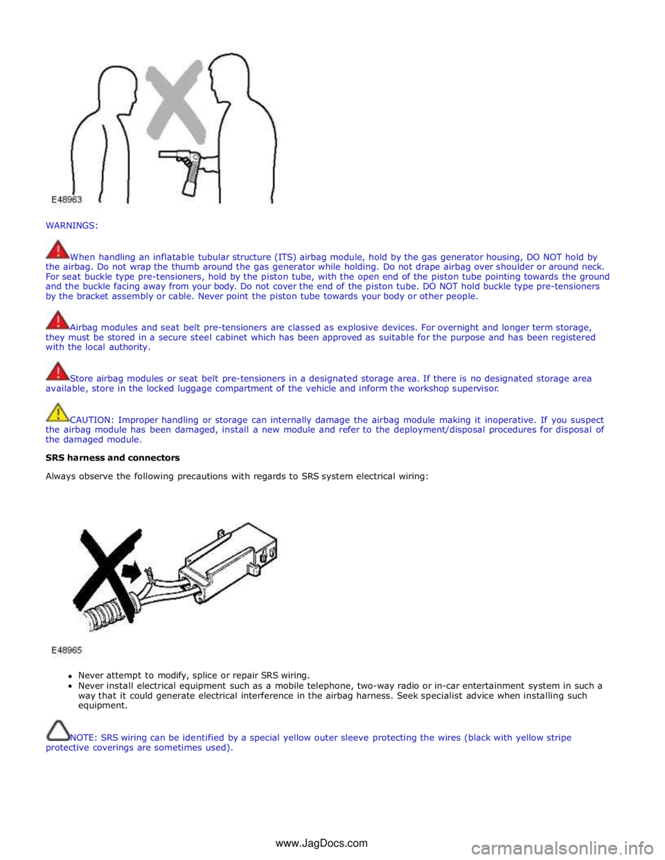
WARNINGS:
When handling an inflatable tubular structure (ITS) airbag module, hold by the gas generator housing, DO NOT hold by
the airbag. Do not wrap the thumb around the gas generator while holding. Do not drape airbag over shoulder or around neck.
For seat buckle type pre-tensioners, hold by the piston tube, with the open end of the piston tube pointing towards the ground
and the buckle facing away from your body. Do not cover the end of the piston tube. DO NOT hold buckle type pre-tensioners
by the bracket assembly or cable. Never point the piston tube towards your body or other people.
Airbag modules and seat belt pre-tensioners are classed as explosive devices. For overnight and longer term storage,
they must be stored in a secure steel cabinet which has been approved as suitable for the purpose and has been registered
with the local authority.
Store airbag modules or seat belt pre-tensioners in a designated storage area. If there is no designated storage area
available, store in the locked luggage compartment of the vehicle and inform the workshop supervisor.
CAUTION: Improper handling or storage can internally damage the airbag module making it inoperative. If you suspect
the airbag module has been damaged, install a new module and refer to the deployment/disposal procedures for disposal of
the damaged module.
SRS harness and connectors
Always observe the following precautions with regards to SRS system electrical wiring:
Never attempt to modify, splice or repair SRS wiring.
Never install electrical equipment such as a mobile telephone, two-way radio or in-car entertainment system in such a
way that it could generate electrical interference in the airbag harness. Seek specialist advice when installing such
equipment.
NOTE: SRS wiring can be identified by a special yellow outer sleeve protecting the wires (black with yellow stripe
protective coverings are sometimes used). www.JagDocs.com
Page 79 of 3039

1 - Minor component movement clockwise/counterclockwise 2 - Major component movement clockwise/counterclockwise 3 - Component movement to the left/right/up/down 4 - Component movement towards/away 5 - 3 dimensional component movement 6 - 2 dimensional component movement 7
3 dimensional component rotation 8
3 dimensional component cycling
Page 137 of 3039

DTC Description Possible Causes Action B10F1-12
Key In Switch - Circuit
short to battery
Keyless vehicle module, key
IN status circuit - short to
power
Refer to the electrical circuit diagrams and check
keyless vehicle module, key IN status circuit for
short to power B10F1-13
Key In Switch - Circuit
open
Keyless vehicle module, key
IN status circuit - open
circuit
Refer to the electrical circuit diagrams and check
keyless vehicle module, key IN status circuit for
open circuit B10F2-11
Sunroof Control -
Circuit short to ground
Sunroof enable signal circuit
- short to ground
Carry out any pinpoint tests associated with this
DTC using the manufacturer approved diagnostic
system. Refer to the electrical circuit diagrams
and check sunroof enable signal circuit for short
to ground B10F2-12
Sunroof Control -
Circuit short to battery
Sunroof enable signal circuit
- short to power
Refer to the electrical circuit diagrams and check
sunroof enable signal circuit for short to power B10F2-13
Sunroof Control -
Circuit open
Sunroof enable signal circuit
- open circuit
Refer to the electrical circuit diagrams and check
sunroof enable signal circuit for open circuit B10F3-11
Left Front Position
Light - Circuit short to
ground
Left front side lamps circuit -
short to ground
Carry out any pinpoint tests associated with this
DTC using the manufacturer approved diagnostic
system. Refer to the electrical circuit diagrams
and check left front side lamps circuit for short to
ground B10F3-15
Left Front Position
Light - Circuit short to
battery or open
Left front side lamps circuit -
short to power, open circuit
Carry out any pinpoint tests associated with this
DTC using the manufacturer approved diagnostic
system. Refer to the electrical circuit diagrams
and check left front side lamps circuit for short to
power, open circuit B10F4-11
Right Front Position
Light - Circuit short to
ground
Right front side lamps circuit
- short to ground
Carry out any pinpoint tests associated with this
DTC using the manufacturer approved diagnostic
system. Refer to the electrical circuit diagrams
and check right front side lamps circuit for short
to ground B10F4-15
Right Front Position
Light - Circuit short to
battery or open
Right front side lamps circuit
- short to power, open circuit
Carry out any pinpoint tests associated with this
DTC using the manufacturer approved diagnostic
system. Refer to the electrical circuit diagrams
and check right front side lamps circuit for short
to power, open circuit B10F8-12
Accessory socket 'A'
relay - Circuit short to
battery
Accessory socket 'A' relay
control circuit - short to
power
Carry out any pinpoint tests associated with this
DTC using the manufacturer approved diagnostic
system. Refer to the electrical circuit diagrams
and check accessory socket 'A' relay control circuit
for short to power B10F8-14
Accessory socket 'A'
relay - Circuit short to
ground or open
Accessory socket 'A' relay
control circuit - short to
ground, open circuit
Refer to the electrical circuit diagrams and check
accessory socket 'A' relay control circuit for short
to ground, open circuit B10F9-12
Accessory socket 'B'
relay - Circuit short to
battery
Front powerpoint, trailer tow
connector, road pricing
connector, sunblind power
supply circuits - short to
power
Refer to the electrical circuit diagrams and check
front powerpoint, trailer tow connector, road
pricing connector, sunblind power supply circuits
for short to power B10F9-14
Accessory socket 'B'
relay - Circuit short to
ground or open
Front powerpoint, trailer tow
connector, road pricing
connector, sunblind power
supply circuits - short to
ground, open circuit
Refer to the electrical circuit diagrams and check
front powerpoint, trailer tow connector, road
pricing connector, sunblind power supply circuits
for short to ground, open circuit
Page 138 of 3039

DTC Description Possible Causes Action B10F9-93
Accessory socket 'B'
relay - No operation
Front powerpoint, trailer tow
connector, road pricing
connector, sunblind power
supply circuits - short to
power, ground, open circuit
Carry out any pinpoint tests associated with this
DTC using the manufacturer approved diagnostic
system. Refer to the electrical circuit diagrams
and check front powerpoint, trailer tow connector,
road pricing connector, sunblind power supply
circuits for short to power, ground, open circuit B10FA-93
Delayed Power Off
relay - No operation
ADRC ECM, roof header
console lamp, glove box
lamp , RH/LH footwell
lamps, JAG Sense glove box
module, RH/LH sunvisor
lamps, rear dome lamps
switched power circuits -
short to power, open circuit
Carry out any pinpoint tests associated with this
DTC using the manufacturer approved diagnostic
system. Refer to the electrical circuit diagrams
and check ADRC ECM, roof header console lamp,
glove box lamp , RH/LH footwell lamps, JAG
Sense glove box module, RH/LH sunvisor lamps,
rear dome lamps switched power circuits for short
to power, open circuit B10FF-11
Ignition control -
Circuit short to ground
ECM and FPDB ignition
control circuit - short to
ground
Carry out any pinpoint tests associated with this
DTC using the manufacturer approved diagnostic
system. Refer to the electrical circuit diagrams
and check ECM and FPDB ignition control circuit
for short to ground B10FF-13
Ignition control -
Circuit open
ECM and FPDB ignition
control circuit - open circuit
Carry out any pinpoint tests associated with this
DTC using the manufacturer approved diagnostic
system. Refer to the electrical circuit diagrams
and check ECM and FPDB ignition control circuit
for open circuit B1100-11 O2 sensor heater relay
- Circuit short to
ground
FPDB O2 sensor heater relay
control circuit - short to
ground
Carry out any pinpoint tests associated with this
DTC using the manufacturer approved diagnostic
system. Refer to the electrical circuit diagrams
and check FPDB O2 sensor heater relay control
circuit for short to ground B113D-12
Sunroof Global
Open/Close Control -
Circuit short to battery
Roof opening panel global
open/close control circuit -
short to power
Carry out any pinpoint tests associated with this
DTC using the manufacturer approved diagnostic
system. Refer to the electrical circuit diagrams
and check roof opening panel global open/close
control circuit for short to power B113D-14
Sunroof Global
Open/Close Control -
Circuit short to ground
or open
Roof opening panel global
open/close control circuit -
short to ground, open circuit
Refer to the electrical circuit diagrams and check
roof opening panel global open/close control
circuit for short to ground, open circuit B1140-11
Engine Crank
Authorisation - Circuit
short to ground
Engine crank authorisation
signal circuit - short to
ground
Carry out any pinpoint tests associated with this
DTC using the manufacturer approved diagnostic
system. Refer to the electrical circuit diagrams
and check engine crank authorisation signal circuit
for short to ground B1142-11
Ignition Status 1 -
Circuit short to ground
Ignition supply 1 circuits -
short to ground
Carry out any pinpoint tests associated with this
DTC using the manufacturer approved diagnostic
system. Refer to the electrical circuit diagrams
and check all ignition supply 1 circuits for short to
ground B1143-11
Ignition Status 2 -
Circuit short to ground
Ignition supply 2 circuits -
short to ground
Carry out any pinpoint tests associated with this
DTC using the manufacturer approved diagnostic
system. Refer to the electrical circuit diagrams
and check all ignition supply 2 circuits for short to
ground B1144-11
Heated Steering
Wheel Supply - Circuit
short to ground
Heated steering wheel
supply circuit - short to
ground
Carry out any pinpoint tests associated with this
DTC using the manufacturer approved diagnostic
system. Refer to the electrical circuit diagrams
and check heated steering wheel supply circuit for
short to ground
Page 220 of 3039

DTC Description Possible Causes Action B100A-51 Fuel Pump Authorisation
- Not programmed
RJB fault
Low speed CAN fault
Instrument cluster fault
Check power and ground supplies to RJB. Check CAN
communications between RJB and instrument
cluster. Check power and ground supplies to
instrument cluster B100A-62 Fuel Pump Authorisation
- Signal compare failure
Low speed CAN fault
RJB fault
Instrument cluster fault
Incorrect module
installed
(RJB/Instrument cluster)
Write target SID
synchronisation error
following
re-programming
Noise/EMC related error
Check CAN communications between RJB and
instrument cluster. Check power and ground supplies
to RJB and instrument cluster. Confirm correct
module installed. Re-synchronise ID by
re-configuring the RJB as a new module. Check CAN
network for interference/EMC related issues B100A-63 Fuel Pump Authorisation
- Circuit/component
protection time-out
RJB fault
Low speed CAN fault
Instrument cluster fault
Low battery voltage <9V
Check power and ground supplies to RJB and
instrument cluster. Check CAN communications
between RJB and instrument cluster. Check battery
is in fully charged and serviceable condition, refer to
the battery care manual B1026-12
Steering Column Lock -
Circuit short to battery
Steering column lock
ground circuit - short to
power
Refer to the electrical circuit diagrams and check
steering column lock ground circuit for short to
power B1087-83
LIN Bus "A" - Value of
signal protection
calculation incorrect
The checksum of the
received LIN frame is
incorrect
Check the battery monitoring system and rear
parking aid system for DTCs and refer to relevant
DTC Index B1087-86
LIN Bus "A" - Signal
invalid
The header of the LIN
message received is
incorrect
Carry out any pinpoint test associated with this DTC
using the manufacturer approved diagnostic system.
Check the battery monitoring system and rear
parking aid system for DTCs and refer to relevant
DTC Index B1087-88 LIN Bus "A" - Bus off
Battery monitoring
system LIN circuit -
short to ground, power
Carry out any pinpoint test associated with this DTC
using the manufacturer approved diagnostic system.
Refer to the electrical circuit diagrams and check
battery monitoring system LIN circuit for short to
ground, power B108A-23
Start Button - Signal
stuck low
Start/Stop switch digital
input signal circuit -
stuck low
Carry out any pinpoint test associated with this DTC
using the manufacturer approved diagnostic system.
Refer to the electrical circuit diagrams and check
Start/Stop switch digital input signal circuit for short
to ground B10A1-11 Trailer Tow Detection -
Circuit short to ground
Trailer tow detection
digital input circuit -
short to ground
Carry out any pinpoint test associated with this DTC
using the manufacturer approved diagnostic system.
Refer to the electrical circuit diagrams and check
trailer tow detection digital input circuit for short to
ground B10AF-12
Blower Fan Relay -
Circuit short to battery
High Side output not
driven - Diagnosis
feedback indicates
output is short to power
Refer to the electrical circuit diagrams and check
blower motor supply circuit for short to power B10AF-14
Blower Fan Relay -
Circuit short to ground
or open
High Side output not
driven - Diagnosis
feedback indicates
output is short to
ground, open circuit
Refer to the electrical circuit diagrams and check
blower motor supply circuit for short to ground, open
circuit
Page 296 of 3039
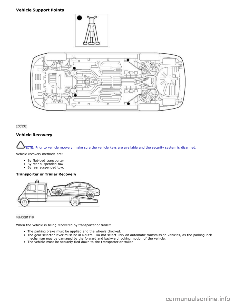
Vehicle Support Points
Vehicle Recovery
NOTE: Prior to vehicle recovery, make sure the vehicle keys are available and the security system is disarmed.
Vehicle recovery methods are:
By flat-bed transporter.
By rear suspended tow.
By rear suspended tow.
Transporter or Trailer Recovery
When the vehicle is being recovered by transporter or trailer:
The parking brake must be applied and the wheels chocked.
The gear selector lever must be in Neutral. Do not select Park on automatic transmission vehicles, as the parking lock
mechanism may be damaged by the forward and backward rocking motion of the vehicle.
The vehicle must be securely tied down to the transporter or trailer.
Page 297 of 3039
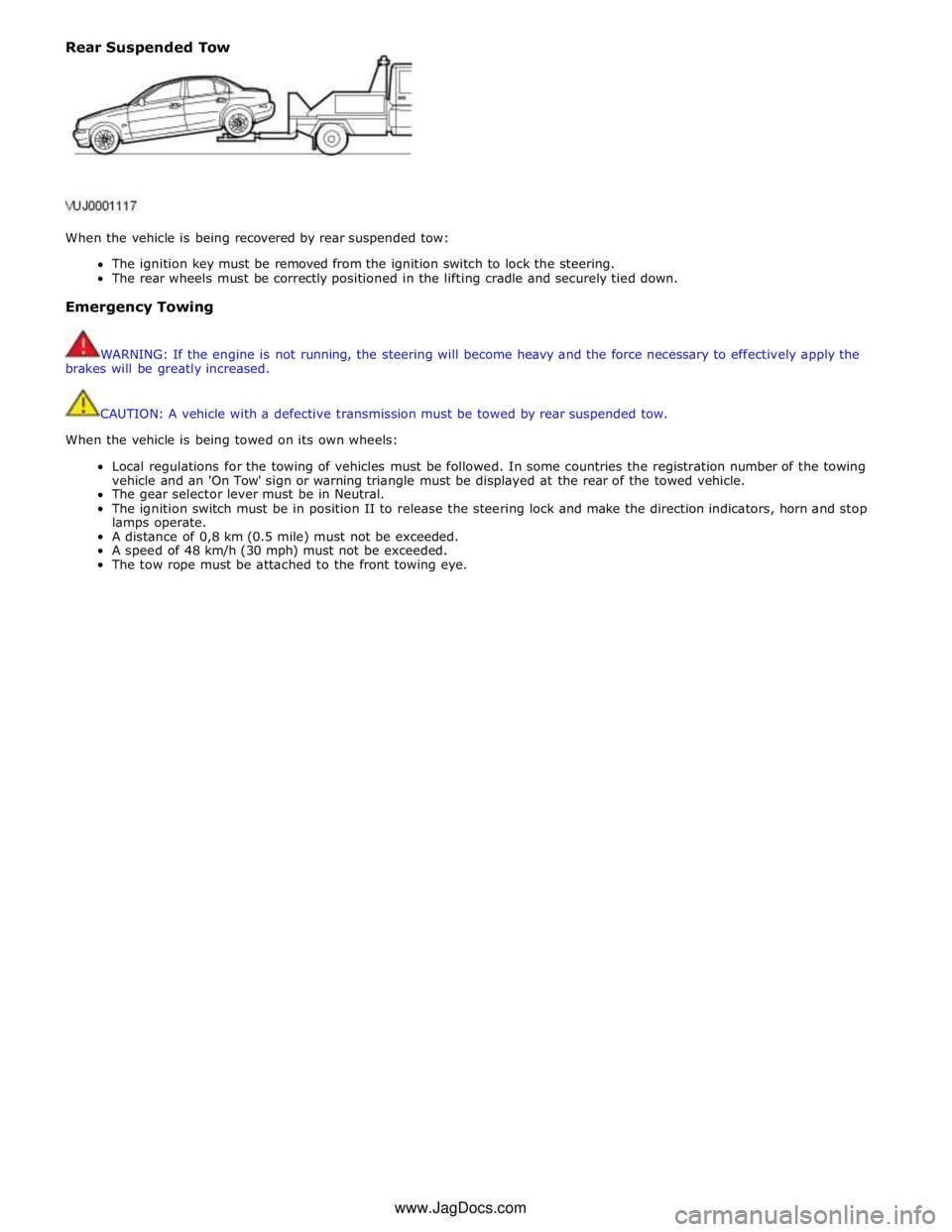
Rear Suspended Tow
When the vehicle is being recovered by rear suspended tow:
The ignition key must be removed from the ignition switch to lock the steering.
The rear wheels must be correctly positioned in the lifting cradle and securely tied down.
Emergency Towing
WARNING: If the engine is not running, the steering will become heavy and the force necessary to effectively apply the
brakes will be greatly increased.
CAUTION: A vehicle with a defective transmission must be towed by rear suspended tow.
When the vehicle is being towed on its own wheels:
Local regulations for the towing of vehicles must be followed. In some countries the registration number of the towing
vehicle and an 'On Tow' sign or warning triangle must be displayed at the rear of the towed vehicle.
The gear selector lever must be in Neutral.
The ignition switch must be in position II to release the steering lock and make the direction indicators, horn and stop
lamps operate.
A distance of 0,8 km (0.5 mile) must not be exceeded.
A speed of 48 km/h (30 mph) must not be exceeded.
The tow rope must be attached to the front towing eye. www.JagDocs.com
Page 302 of 3039
and drive half shaft failure, which could cause serious personal injury and extensive vehicle damage. Failure to follow these
instructions may result in personal injury.
CAUTION: The suspension should not be allowed to hang free. When the CV joint is run at a very high angle, extra
vibration as well as damage to the seals and joints can occur.
The rear suspension lower arm should be supported as far outboard as possible. To bring the vehicle to its correct ride height,
the full weight of the vehicle should be supported in the rear by floor jacks. REFER to: (100-02 Jacking and Lifting)
Jacking (Description and Operation), Lifting (Description and Operation).
1. Raise and support the vehicle. REFER to: (100-02 Jacking and Lifting)
Jacking (Description and Operation), Lifting (Description and Operation).
2. Explore the speed range of interest using the Road Test Quick Checks as previously described.
3. Carry out a coast down in neutral. If the vehicle is free of vibration when operating at a steady indicated speed and
behaves very differently in drive and coast, a transmission concern is likely.
Note, however, that a test on the lift may produce different vibrations and noises than a road test because of the effect of the
lift. It is not unusual to find vibrations on the lift that were not found in the road test. If the condition found on the road can
be duplicated on the lift, carrying out experiments on the lift may save a great deal of time.
Exhaust Neutralization Procedure
1. Raise vehicle on lift and slacken all exhaust fixings.
2. With all fixings loose, neutralize the exhaust system.
3. Tighten all fixings to correct torque, starting at the rear-most point working towards the front of the vehicle.
Symptom Chart
Symptom Possible Cause Action High-speed shake
Wheel end vibration
Engine/transmission
Driveline GO to Pinpoint Test A. Tip-in moan
Air cleaner
Power steering
Powertrain
Engine mounts
Exhaust system GO to Pinpoint Test B. Idle boom/shake/vibration, or shudder
Cable(s)/hoses(s)
Intake air distribution and filtering system
Engine mounts
Exhaust system
Belt/pulleys GO to Pinpoint Test C. Wheel end vibration analysis
Suspension/rear drive halfshaft and CV joints
Tires/wheels
Wheel bearings
CV joint boots GO to Pinpoint Test D. Non-axle noise
Trim/mouldings
A/C system
Accessories GO to Pinpoint Test E. Pinpoint Tests
NOTE: These Pinpoint Tests are designed to take the technician through a step-by-step diagnosis procedure to determine
the cause of a condition. It may not always be necessary to follow the chart to its conclusion. Carry out only the Pinpoint Test
steps necessary to correct the condition. Then check operation of the system to make sure the condition is corrected.
After verifying that the condition has been corrected, make sure all components removed have been installed.
PINPOINT TEST A : HIGH-SPEED SHAKE TEST DETAILS/RESULTS/ACTIONS www.JagDocs.com
Page 470 of 3039
Installation
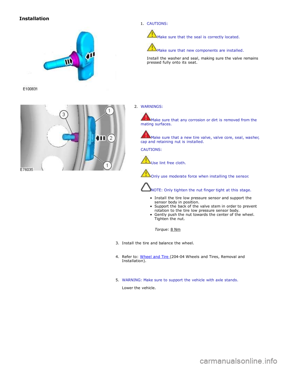
1. CAUTIONS:
Make sure that the seal is correctly located.
Make sure that new components are installed.
Install the washer and seal, making sure the valve remains
pressed fully onto its seat.
2. WARNINGS:
Make sure that any corrosion or dirt is removed from the
mating surfaces.
Make sure that a new tire valve, valve core, seal, washer,
cap and retaining nut is installed.
CAUTIONS:
Use lint free cloth.
Only use moderate force when installing the sensor.
NOTE: Only tighten the nut finger tight at this stage.
Install the tire low pressure sensor and support the
sensor body in position.
Support the back of the valve stem in order to prevent
rotation to the tire low pressure sensor body.
Gently push the nut towards the center of the wheel.
Tighten the nut.
Torque: 8 Nm
3. Install the tire and balance the wheel.
4. Refer to: Wheel and Tire (204-04 Wheels and Tires, Removal and Installation).
5. WARNING: Make sure to support the vehicle with axle stands.
Lower the vehicle.