Aj133 JAGUAR XFR 2010 1.G Workshop Manual
[x] Cancel search | Manufacturer: JAGUAR, Model Year: 2010, Model line: XFR, Model: JAGUAR XFR 2010 1.GPages: 3039, PDF Size: 58.49 MB
Page 164 of 3039
Published: 18-Apr-2014
General Information - Diagnostic Trouble Code (DTC) Index V8 S/C 5.0L
Petrol, DTC: Engine Control Module (ECM)
Description and Operation
Engine Control Module (PCM) 5.0L SC V8 - AJ133
WARNING: Fuel injector voltage will reach 65 Volts during operation and have a high current requirement.
CAUTION: Diagnosis by substitution from a donor vehicle is NOT acceptable. Substitution of control modules does not
guarantee confirmation of a fault, and may also cause additional faults in the vehicle being tested and/or the donor vehicle
NOTES:
If the control module or a component is suspect and the vehicle remains under manufacturer warranty, refer to the
Warranty Policy and Procedures manual, or determine if any prior approval programme is in operation, prior to the installation
of a new module/component.
Generic scan tools may not read the codes listed, or may read only five digit codes. Match the five digits from the scan
tool to the first five digits of the seven digit code listed to identify the fault (the last two digits give additional information
read by the manufacturer-approved diagnostic system).
When performing electrical voltage or resistance tests, always use a digital multimeter (DMM) accurate to three decimal
places, and with an up-to-date calibration certificate. When testing resistance, always take the resistance of the DMM leads
into account.
Check and rectify basic faults before beginning diagnostic routines involving pinpoint tests.
If DTCs are recorded and, after performing the pinpoint tests, a fault is not present, an intermittent concern may be the
cause. Always check for loose connections and corroded terminals.
Check DDW for open campaigns. Refer to the corresponding bulletins and SSMs which may be valid for the specific
customer complaint and carry out the recommendations as required.
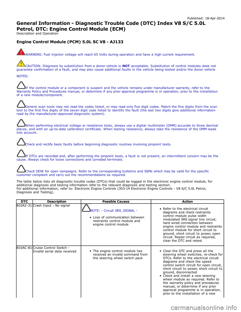
The table below lists all diagnostic trouble codes (DTCs) that could be logged in the electronic engine control module, for
additional diagnosis and testing information refer to the relevant diagnosis and testing section.
For additional information, refer to: Electronic Engine Controls (303-14 Electronic Engine Controls - V8 S/C 5.0L Petrol,
Diagnosis and Testing).
DTC Description Possible Causes Action B10A2-31 Crash Input - No signal
NOTE: - Circuit SRS_SIGNAL -
Loss of communication between
restraints control module and
engine control module
Refer to the electrical circuit
diagrams and check restraints
control module pulse width
modulated SRS signal line circuit,
hard wired connection between
engine control module and restraints
control module for short circuit to
ground, short circuit to power, open
circuit. Repair circuit as required,
clear the DTC and retest B10AC-81
Cruise Control Switch -
Invalid serial data received
The engine control module has
received an invalid command from
the steering wheel switch pack
Clear the DTC and press all the
steering wheel switches, re-check for
DTCs. Refer to the electrical circuit
diagrams and check the speed
control switch circuit for open circuit,
short circuit to power, short circuit to
ground, disconnected
Check and install a new steering
wheel module as required. Refer to
the warranty policy and procedures
manual, or determine if any prior
approval programme is in operation,
prior to the installation of a new
Page 1376 of 3039

Published: 11-May-2011
Electronic Engine Controls - V8 S/C 5.0L Petrol - Camshaft Position (CMP)
Sensor LH
Removal and Installation
Removal
NOTE: Removal steps in this procedure may contain installation details.
1. Disconnect the battery ground cable.
Refer to: Specifications (414-00 Charging System - General Information,
Specifications).
2. WARNING: Make sure to support the vehicle with axle stands.
Raise and support the vehicle.
3. Refer to: Thermostat Housing - 5.0L SC V8 - AJ133 (303-03 Engine
Cooling - 5.0L NA V8 - AJ133/5.0L SC V8 - AJ133, Removal and
Installation).
Installation
4. NOTE: Some variation in the illustrations may occur,
but the essential information is always correct.
Torque: 10 Nm
1. CAUTIONS:
Make sure that the mating faces are clean and free of foreign
material.
Make sure that the sensor tip is clean and free of foreign material.
NOTE: Lubricate the O-ring seal with clean engine oil.
To install, reverse the removal procedure. www.JagDocs.com
Page 1377 of 3039

Published: 11-May-2011
Electronic Engine Controls - V8 S/C 5.0L Petrol - Camshaft Position (CMP)
Sensor RH
Removal and Installation
Removal
NOTE: Removal steps in this procedure may contain installation details.
1. Disconnect the battery ground cable.
Refer to: Specifications (414-00 Charging System - General Information,
Specifications).
2. WARNING: Make sure to support the vehicle with axle stands.
Raise and support the vehicle.
3. Refer to: Thermostat Housing - 5.0L SC V8 - AJ133 (303-03 Engine
Cooling - 5.0L NA V8 - AJ133/5.0L SC V8 - AJ133, Removal and
Installation).
Installation
4. NOTE: Some variation in the illustrations may occur,
but the essential information is always correct.
Torque: 10 Nm
1. CAUTIONS:
Make sure that the mating faces are clean and free of foreign
material.
Make sure that the sensor tip is clean and free of foreign material.
NOTE: Lubricate the O-ring seal with clean engine oil.
To install, reverse the removal procedure.