Pedestrian protection JAGUAR XFR 2010 1.G Workshop Manual
[x] Cancel search | Manufacturer: JAGUAR, Model Year: 2010, Model line: XFR, Model: JAGUAR XFR 2010 1.GPages: 3039, PDF Size: 58.49 MB
Page 3 of 3039

Diagnostic Trouble Code (DTC) IndexDTC: Occupant Classification System (OCS)
Diagnostic Trouble Code (DTC) IndexDTC: Parking Aid Module (PAM)
Diagnostic Trouble Code (DTC) IndexDTC: Pedestrian Protection System Control Module (PPSCM)
Diagnostic Trouble Code (DTC) IndexDTC: Rear Differential Control Module (RDCM)
Diagnostic Trouble Code (DTC) IndexDTC: Rear Junction Box (RJB)
Diagnostic Trouble Code (DTC) IndexDTC: Remote Keyless Entry Module (RFA)
Diagnostic Trouble Code (DTC) IndexDTC: Restraints Control Module (RCM)
Diagnostic Trouble Code (DTC) IndexDTC: Satellite Digital Audio Radio System Module (SARM)
Diagnostic Trouble Code (DTC) IndexDTC: Speed Control Module (CCM)
Diagnostic Trouble Code (DTC) IndexDTC: Steering Column Lock Module (VIM)
Diagnostic Trouble Code (DTC) IndexDTC: Television Module (TVM)
Diagnostic Trouble Code (DTC) IndexDTC: Tire Pressure Monitoring System Module (TPM)
Diagnostic Trouble Code (DTC) IndexDTC: Touch Screen Display (FCDIM)
Diagnostic Trouble Code (DTC) IndexVehicles With: 6HP28 6-Speed Automatic Transmission, DTC:
Transmission Control Module (TCM)
Diagnostic Trouble Code (DTC) IndexDTC: Transmission Shift Module (GSM)
Diagnostic Trouble Code (DTC) IndexDTC: Portable Audio Interface Control Module (PAICM)
Diagnostic Trouble Code (DTC) IndexDTC: Hybrid Digital Radio Control Module (HDRCM)
Diagnostic Trouble Code (DTC) IndexDTC: Infotainment Control Module (ICM)
Diagnostic Trouble Code (DTC) IndexDTC: Telephone Module (TEL)100-01: Identification Codes
Description and OperationIdentification Codes100-02: Jacking and Lifting
Description and OperationJacking
Lifting100-04: Noise, Vibration and Harshness
Description and OperationNoise, Vibration and Harshness (NVH)Diagnosis and TestingNoise, Vibration and Harshness (NVH)General ProceduresExhaust System Neutralizing2: Chassis
204: Suspension
204-00: Suspension System - General InformationSpecificationDiagnosis and TestingSuspension SystemGeneral ProceduresCamber and Caster Adjustment
Page 30 of 3039

System Operation and Component DescriptionDiagnosis and TestingAir Bag and Safety Belt Pretensioner Supplemental Restraint System (SRS)General ProceduresAir Bag DisposalRemoval and InstallationB-Pillar Side Impact Sensor
Clockspring
C-Pillar Side Impact Sensor
Crash Sensor
Driver Air Bag Module
Occupant Classification Sensor
Passenger Air Bag Module
Restraints Control Module (RCM)
Side Air Bag Module (76.73.47)
Side Air Curtain Module501-20C: Pedestrian Protection System
Description and OperationComponent Location
Overview
System Operation and Component DescriptionDiagnosis and TestingPedestrian Protection SystemRemoval and InstallationPedestrian Impact Sensor
Pedestrian Protection Hood Actuator LH
Pedestrian Protection Hood Actuator RH
Pedestrian Protection Module501-25A: Body Repairs - General Information
Description and OperationBody Repairs501-25B: Body Repairs - Corrosion Protection
Description and OperationCorrosion Protection501-25C: Body Repairs - Water Leaks
Description and OperationWater Leaks501-26: Body Repairs - Vehicle Specific Information and Tolerance Checks
Description and OperationBody and Frame501-27: Front End Sheet Metal Repairs
Description and OperationFront End Sheet Metal
Page 215 of 3039
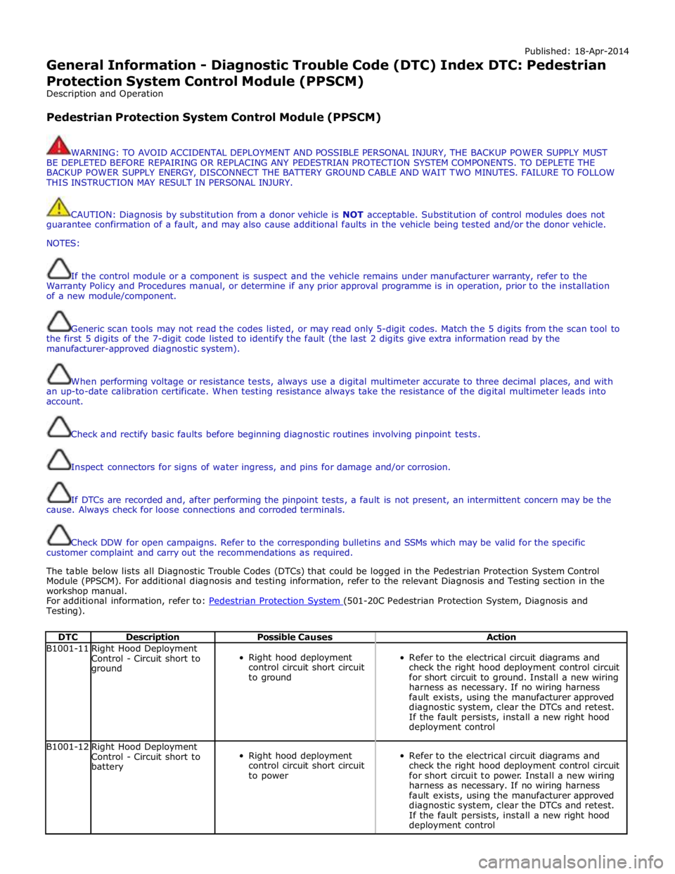
Published: 18-Apr-2014
General Information - Diagnostic Trouble Code (DTC) Index DTC: Pedestrian
Protection System Control Module (PPSCM)
Description and Operation
Pedestrian Protection System Control Module (PPSCM)
WARNING: TO AVOID ACCIDENTAL DEPLOYMENT AND POSSIBLE PERSONAL INJURY, THE BACKUP POWER SUPPLY MUST
BE DEPLETED BEFORE REPAIRING OR REPLACING ANY PEDESTRIAN PROTECTION SYSTEM COMPONENTS. TO DEPLETE THE
BACKUP POWER SUPPLY ENERGY, DISCONNECT THE BATTERY GROUND CABLE AND WAIT TWO MINUTES. FAILURE TO FOLLOW
THIS INSTRUCTION MAY RESULT IN PERSONAL INJURY.
CAUTION: Diagnosis by substitution from a donor vehicle is NOT acceptable. Substitution of control modules does not
guarantee confirmation of a fault, and may also cause additional faults in the vehicle being tested and/or the donor vehicle.
NOTES:
If the control module or a component is suspect and the vehicle remains under manufacturer warranty, refer to the
Warranty Policy and Procedures manual, or determine if any prior approval programme is in operation, prior to the installation
of a new module/component.
Generic scan tools may not read the codes listed, or may read only 5-digit codes. Match the 5 digits from the scan tool to
the first 5 digits of the 7-digit code listed to identify the fault (the last 2 digits give extra information read by the
manufacturer-approved diagnostic system).
When performing voltage or resistance tests, always use a digital multimeter accurate to three decimal places, and with
an up-to-date calibration certificate. When testing resistance always take the resistance of the digital multimeter leads into
account.
Check and rectify basic faults before beginning diagnostic routines involving pinpoint tests.
Inspect connectors for signs of water ingress, and pins for damage and/or corrosion.
If DTCs are recorded and, after performing the pinpoint tests, a fault is not present, an intermittent concern may be the
cause. Always check for loose connections and corroded terminals.
Check DDW for open campaigns. Refer to the corresponding bulletins and SSMs which may be valid for the specific
customer complaint and carry out the recommendations as required.
The table below lists all Diagnostic Trouble Codes (DTCs) that could be logged in the Pedestrian Protection System Control
Module (PPSCM). For additional diagnosis and testing information, refer to the relevant Diagnosis and Testing section in the
workshop manual.
For additional information, refer to: Pedestrian Protection System (501-20C Pedestrian Protection System, Diagnosis and Testing).
DTC Description Possible Causes Action B1001-11
Right Hood Deployment
Control - Circuit short to
ground
Right hood deployment
control circuit short circuit
to ground
Refer to the electrical circuit diagrams and
check the right hood deployment control circuit
for short circuit to ground. Install a new wiring
harness as necessary. If no wiring harness
fault exists, using the manufacturer approved
diagnostic system, clear the DTCs and retest.
If the fault persists, install a new right hood
deployment control B1001-12
Right Hood Deployment
Control - Circuit short to
battery
Right hood deployment
control circuit short circuit
to power
Refer to the electrical circuit diagrams and
check the right hood deployment control circuit
for short circuit to power. Install a new wiring
harness as necessary. If no wiring harness
fault exists, using the manufacturer approved
diagnostic system, clear the DTCs and retest.
If the fault persists, install a new right hood
deployment control
Page 1805 of 3039

DTC Description Possible Cause Action U013900
Lost
Communication
with Suspension
Control Module 'B'
Loss of CAN communication
with adaptive damping module Carry out any pinpoint tests associated with this DTC using
the manufacturer approved diagnostic system. Check
adaptive damping module for DTCs and refer to the relevant
DTC Index U014000
Lost
Communication
With Body
Control Module
Loss of CAN communication
with CJB Carry out any pinpoint tests associated with this DTC using
the manufacturer approved diagnostic system. Check CJB for
DTCs and refer to the relevant DTC Index U014200
Lost
Communication
With Body
Control Module
"B"
Loss of CAN communication
with RJB Carry out any pinpoint tests associated with this DTC using
the manufacturer approved diagnostic system. Check RJB for
DTCs and refer to the relevant DTC Index U015100
Lost
Communication
With Restraints
Control Module
Loss of CAN communication
with RCM Carry out any pinpoint tests associated with this DTC using
the manufacturer approved diagnostic system. Check RCM for
DTCs and refer to the relevant DTC Index U015600
Lost
Communication
with Information
Centre 'A'
Loss of CAN communication
with information and
entertainment control module Carry out any pinpoint tests associated with this DTC using
the manufacturer approved diagnostic system. Check
information and entertainment control module for DTCs and
refer to the relevant DTC Index U016400
Lost
Communication
with HVAC
Control Module
Loss of CAN communication
with climate control module Carry out any pinpoint tests associated with this DTC using
the manufacturer approved diagnostic system. Check climate
control module for DTCs and refer to the relevant DTC Index U019900
Lost
Communication
with Door Control
Module 'A'
Loss of CAN communication
with driver door module (DDM) Carry out any pinpoint tests associated with this DTC using
the manufacturer approved diagnostic system. Check DDM for
DTCs and refer to the relevant DTC Index U020000
Lost
Communication
with Door Control
Module 'B'
Loss of CAN communication
with passenger door module
(PDM) Carry out any pinpoint tests associated with this DTC using
the manufacturer approved diagnostic system. Check PDM for
DTCs and refer to the relevant DTC Index U020800
Lost
Communication
with Seat Control
Module 'A'
Loss of CAN communication
with driver seat module (DSM) Carry out any pinpoint tests associated with this DTC using
the manufacturer approved diagnostic system. Check DSM for
DTCs and refer to the relevant DTC Index U021400
Lost
Communication
with Remote
Function
Actuation
Loss of CAN communication
with keyless vehicle module
(KVM) Carry out any pinpoint tests associated with this DTC using
the manufacturer approved diagnostic system. Check KVM for
DTCs and refer to the relevant DTC Index U024100
Lost
Communication
with Headlamp
Control Module 'A'
Loss of CAN communication
with headlamp control module Carry out any pinpoint tests associated with this DTC using
the manufacturer approved diagnostic system. Check
headlamp control module for DTCs and refer to the relevant
DTC Index U025000
Lost
Communication
with Impact
Classification System Module
Loss of CAN communication
with pedestrian protection
module Carry out any pinpoint tests associated with this DTC using
the manufacturer approved diagnostic system. Check
pedestrian protection module for DTCs and refer to the
relevant DTC Index U025600
Lost
Communication
with Front
Controls Interface
Module 'A'
Loss of CAN communication
with integrated control panel Carry out any pinpoint tests associated with this DTC using
the manufacturer approved diagnostic system. Check
integrated control panel for DTCs and refer to the relevant
DTC Index U030000
Internal Control
Module Software
Incompatibility
Invalid configuration message
is received Re-configure the RJB using the manufacturer approved
diagnostic system. Clear the DTC and retest. If the DTC is
still logged suspect the instrument cluster, refer to the new
module/component installation note at the top of the DTC
Index U040268
Invalid data
received from
TCM
Algorithm based failures -
events information Check TCM for DTCs and refer to the relevant DTC Index U200411
Auxiliary Switch
Pack
Auxiliary switch signal circuit -
short to ground Refer to the electrical circuit diagrams and check auxiliary
switch signal circuit for short to ground U200415
Auxiliary Switch
Pack
Auxiliary switch signal circuit -
short to power, open circuit Carry out any pinpoint tests associated with this DTC using
the manufacturer approved diagnostic system. Refer to the
electrical circuit diagrams and check auxiliary switch signal
circuit for short to power, open circuit
Page 1827 of 3039
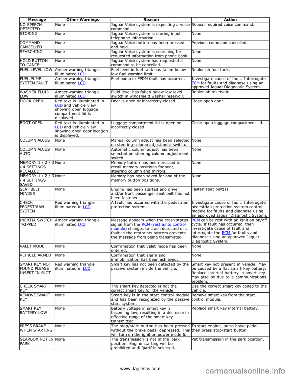
NO SPEECH
DETECTED None
Jaguar Voice system is expecting a voice
command . Repeat required voice command. STORING None
Jaguar Voice system is storing input telephone information. None COMMAND
CANCELLED None
Jaguar Voice button has been pressed
and held. Previous command cancelled. SEARCHING None
Jaguar Voice system is searching for requested information from phone book. None HOLD BUTTON TO CANCEL None
Jaguar Voice system has requested a
command to be cancelled. None FUEL LEVEL LOW
Amber warning triangle
illuminated LCD. Fuel level in fuel tank has fallen below
low fuel warning limit. Replenish fuel tank. FUEL PUMP
SYSTEM FAULT Amber warning triangle
illuminated LCD. Fuel pump or FPDM fault has occurred.
Investigate cause of fault. Interrogate
ECM for faults and diagnose using an approved Jaguar Diagnostic System. WASHER FLUID
LOW Amber warning triangle
illuminated LCD. Fluid level has fallen below low level
switch in windshield washer reservoir. Replenish reservoir. DOOR OPEN
Red text is illuminated in
LCD and vehicle view Door is open or incorrectly closed. Close open door. showing open luggage
compartment lid is
displayed. BOOT OPEN
Red text is illuminated in
LCD and vehicle view Luggage compartment lid is open or incorrectly closed. Close open luggage compartment lid. showing open door location
is displayed. COLUMN ADJUST None
Manual column adjust has been selected
on steering column adjustment switch. None COLUMN ADJUST
AUTO None
Automatic column adjust has been
selected on steering column adjustment
switch. None MEMORY 1 / 2 / 3 / 4 SETTINGS
RECALLED None
Memory button has been pressed to
recall memory positions for seat, steering column and mirrors. None MEMORY 1 / 2 / 3 / 4 SETTINGS
SAVED None
Memory has been saved for one of the
memory button positions. None SEAT BELT
MINDER None
Engine has been started and driver
and/or front passenger seat belt has not
been fastened. Fasten seat belt(s). CHECK
PEDESTRIAN
SYSTEM Red warning triangle
illuminated in LCD. A fault has occurred with the pedestrian
protection system. Investigate cause of fault. Interrogate
pedestrian protection system control
module for faults and diagnose using
an approved Jaguar Diagnostic System. INERTIA SWITCH TRIPPED Amber warning triangle
illuminated LCD. Message appears when the crash status
signal from the RCM (restraints control
module) changes to crash detected or a
fault in the restraints system prevents
the message from being transmitted. RCM can be rest with an ignition on/off cycle. If fault has occurred, then
investigate cause of fault and
interrogate the RCM for faults and diagnose using an approved Jaguar
Diagnostic System. VALET MODE None
Confirmation that valet mode has been
entered. None VEHICLE ARMED None
Confirmation that alarm and
immobilization has been achieved. None SMART KEY NOT
FOUND PLEASE
INSERT IN SLOT Red warning triangle
illuminated in LCD. Smart key has not been detected by the
passive system inside the vehicle. Smart key not present in vehicle. May
be caused by a flat smart key battery.
Replace internal battery in smart key.
May also be due to a communications problem. CHECK SMART
KEY None The smart key detected is not the
correct smart key for the vehicle. Use the correct smart key coded to the
vehicle. REMOVE SMART
KEY None
Smart key is in the start control module
and has been recognized by the passive
start system. Remove smart key from the start
control module. SMART KEY
BATTERY LOW None
Battery voltage in smart key is
becoming low, resulting in a decrease in
effective range of the smart key
transmitter. Replace smart key internal battery. PRESS BRAKE
WHEN STARTING None The stop/start button has been pressed
without the brake pedal depressed. This
will turn on the ignition power mode 6. To start engine, press brake pedal,
then press stop/start button. GEARBOX NOT IN
PARK None The transmission is not in the 'park'
position. Engine starting will be prohibited until 'park' is selected. Put transmission in the park position. www.JagDocs.com
Page 2073 of 3039
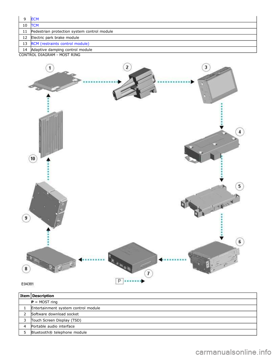
10 TCM 11 Pedestrian protection system control module 12 Electric park brake module 13 RCM (restraints control module) 14 Adaptive damping control module CONTROL DIAGRAM - MOST RING
Item Description P = MOST ring 1 Entertainment system control module 2 Software download socket 3 Touch Screen Display (TSD) 4 Portable audio interface 5 Bluetooth® telephone module
Page 2136 of 3039

Body Panels, Removal and Installation).
2. Remove the engine compartment brace.
3. Remove the secondary bulkhead LH panel.
For additional information, refer to: Secondary Bulkhead Panel LH - 3.0L NA V6 - AJ27 (501-02 Front End Body Panels, Removal and Installation).
4. Remove the pedestrian protection actuator.
Reposition the pedestrian protection hood actuator.
Page 2137 of 3039
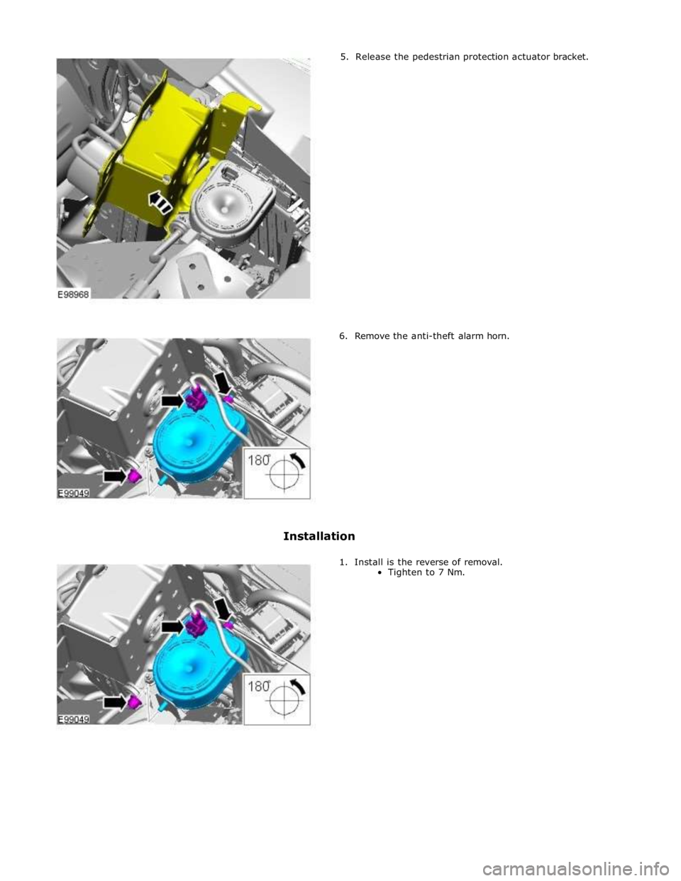
5. Release the pedestrian protection actuator bracket.
6. Remove the anti-theft alarm horn.
Installation
1. Install is the reverse of removal.
Tighten to 7 Nm.
Page 2167 of 3039

10 Diagnostic socket 11 Pedestrian protection control module 12 Electric steering column lock 13 TCM 14 ABS (anti-lock brake system) module COMPONENT LOCATION - MOST
Item Description NOTE: LHD vehicle shown 1 Touch Screen Display (TSD) 2 Integrated audio module 3 Entertainment system control module 4 Digital Audio Broadcast (DAB)/Satellite Digital Audio Radio System (SDARS) 5 Multimedia module
Page 2170 of 3039
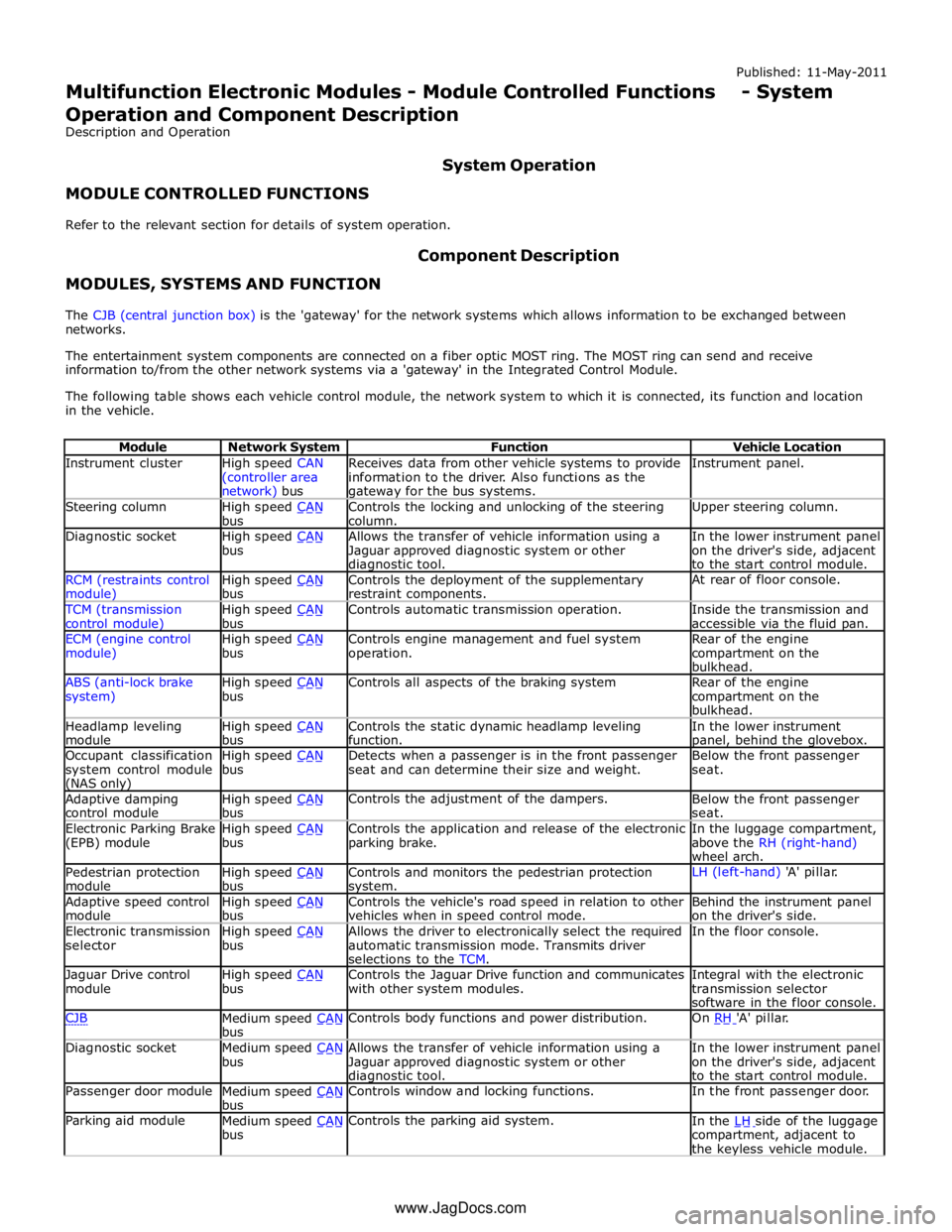
Instrument cluster
High speed CAN
(controller area network) bus Receives data from other vehicle systems to provide
information to the driver. Also functions as the gateway for the bus systems. Instrument panel. Steering column
High speed CAN bus Controls the locking and unlocking of the steering
column. Upper steering column. Diagnostic socket
High speed CAN bus Allows the transfer of vehicle information using a
Jaguar approved diagnostic system or other diagnostic tool. In the lower instrument panel
on the driver's side, adjacent
to the start control module. RCM (restraints control module) High speed CAN bus Controls the deployment of the supplementary
restraint components. At rear of floor console. TCM (transmission
control module) High speed CAN bus Controls automatic transmission operation.
Inside the transmission and
accessible via the fluid pan. ECM (engine control
module) High speed CAN bus Controls engine management and fuel system
operation. Rear of the engine
compartment on the
bulkhead. ABS (anti-lock brake
system) High speed CAN bus Controls all aspects of the braking system
Rear of the engine
compartment on the
bulkhead. Headlamp leveling
module High speed CAN bus Controls the static dynamic headlamp leveling
function. In the lower instrument panel, behind the glovebox. Occupant classification
system control module (NAS only) High speed CAN bus Detects when a passenger is in the front passenger
seat and can determine their size and weight. Below the front passenger
seat. Adaptive damping
control module High speed CAN bus Controls the adjustment of the dampers.
Below the front passenger
seat. Electronic Parking Brake
(EPB) module High speed CAN bus Controls the application and release of the electronic
parking brake. In the luggage compartment,
above the RH (right-hand)
wheel arch. Pedestrian protection
module High speed CAN bus Controls and monitors the pedestrian protection system. LH (left-hand) 'A' pillar. Adaptive speed control
module High speed CAN bus Controls the vehicle's road speed in relation to other
vehicles when in speed control mode. Behind the instrument panel
on the driver's side. Electronic transmission
selector High speed CAN bus Allows the driver to electronically select the required
automatic transmission mode. Transmits driver
selections to the TCM. In the floor console. Jaguar Drive control
module High speed CAN bus Controls the Jaguar Drive function and communicates
with other system modules. Integral with the electronic
transmission selector
software in the floor console. CJB
Medium speed CAN bus Controls body functions and power distribution. On RH 'A' pillar. Diagnostic socket
Medium speed CAN bus Allows the transfer of vehicle information using a
Jaguar approved diagnostic system or other diagnostic tool. In the lower instrument panel
on the driver's side, adjacent
to the start control module. Passenger door module
Medium speed CAN bus Controls window and locking functions. In the front passenger door. Parking aid module
Medium speed CAN bus Controls the parking aid system.
In the LH side of the luggage compartment, adjacent to
the keyless vehicle module. www.JagDocs.com