battery capacity JAGUAR XFR 2010 1.G Workshop Manual
[x] Cancel search | Manufacturer: JAGUAR, Model Year: 2010, Model line: XFR, Model: JAGUAR XFR 2010 1.GPages: 3039, PDF Size: 58.49 MB
Page 67 of 3039

Do not empty fuel while working in a workshop or a pit
Ensure that working area is well ventilated
Ensure that any work on the fuel system is only carried out by experienced and well qualified maintenance personnel
Ensure that fume extraction equipment is used where appropriate
Fume extraction equipment must be in operation when solvents are used e.g. Trichloroethane, white spirit, sbp3,
methylene chloride, perchlorethylene. Do not smoke in the vicinity of volatile degreasing agents.
Whenever possible, use a ramp or pit whilst working beneath a vehicle, in preference to jacking. Position chocks at the wheels
as well as applying the parking brake. Never rely on a jack alone to support a vehicle. Use axle stands, or blocks carefully
placed at the jacking points, to provide a rigid location. Check that any lifting equipment used has adequate capacity and is
fully serviceable. Ensure that a suitable form of fire extinguisher is conveniently located. When using electrical tools and
equipment, inspect the power lead for damage and check that it is properly earthed. Disconnect the earth (grounded) terminal
of the vehicle battery. Do not disconnect any pipes of the air conditioning refrigeration system unless you are trained and
instructed to do so. A refrigerant is used which can cause blindness if allowed to come into contact with the eyes. Ensure that
adequate ventilation is provided when volatile degreasing agents are being used.
Adhere strictly to handling and safety instructions given on containers and labels. Keep oils and solvents away from naked
flames and other sources of ignition. Do not apply heat in an attempt to free seized nuts or fittings; as well as causing
damage to protective coatings, there is a risk of damage from stray heat to electronic equipment and brake lines. Do not leave
tools, equipment, spilt oil etc. around the work area. Wear protective overalls and use barrier cream when necessary.
Environmental Protection
In some countries it is illegal to pour used oil onto the ground, down sewers or drains, or into water courses. The burning of
used engine oil in small space heaters or boilers is not recommended unless emission control equipment is installed. Dispose
of used oil through authorized waste disposal contractors, to licensed waste disposal sites or to the waste oil reclamation
trade. If in doubt, contact the Local Authority for advice on disposal facilities.
Page 1344 of 3039
Published: 11-May-2011
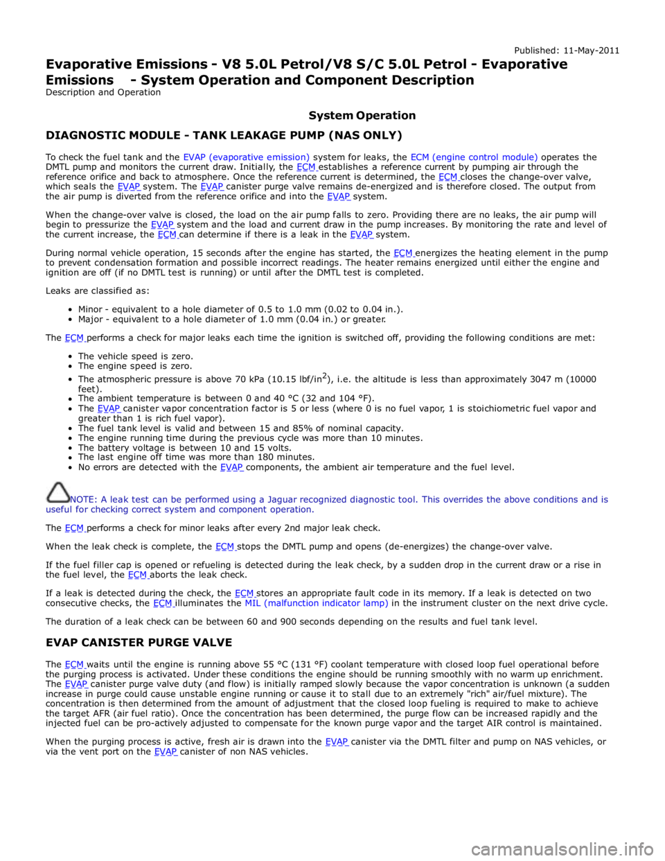
Evaporative Emissions - V8 5.0L Petrol/V8 S/C 5.0L Petrol - Evaporative Emissions - System Operation and Component Description
Description and Operation
System Operation DIAGNOSTIC MODULE - TANK LEAKAGE PUMP (NAS ONLY)
To check the fuel tank and the EVAP (evaporative emission) system for leaks, the ECM (engine control module) operates the
DMTL pump and monitors the current draw. Initially, the ECM establishes a reference current by pumping air through the reference orifice and back to atmosphere. Once the reference current is determined, the ECM closes the change-over valve, which seals the EVAP system. The EVAP canister purge valve remains de-energized and is therefore closed. The output from the air pump is diverted from the reference orifice and into the EVAP system.
When the change-over valve is closed, the load on the air pump falls to zero. Providing there are no leaks, the air pump will
begin to pressurize the EVAP system and the load and current draw in the pump increases. By monitoring the rate and level of the current increase, the ECM can determine if there is a leak in the EVAP system.
During normal vehicle operation, 15 seconds after the engine has started, the ECM energizes the heating element in the pump to prevent condensation formation and possible incorrect readings. The heater remains energized until either the engine and
ignition are off (if no DMTL test is running) or until after the DMTL test is completed.
Leaks are classified as:
Minor - equivalent to a hole diameter of 0.5 to 1.0 mm (0.02 to 0.04 in.).
Major - equivalent to a hole diameter of 1.0 mm (0.04 in.) or greater.
The ECM performs a check for major leaks each time the ignition is switched off, providing the following conditions are met: The vehicle speed is zero.
The engine speed is zero.
The atmospheric pressure is above 70 kPa (10.15 lbf/in2
), i.e. the altitude is less than approximately 3047 m (10000
feet).
The ambient temperature is between 0 and 40 °C (32 and 104 °F).
The EVAP canister vapor concentration factor is 5 or less (where 0 is no fuel vapor, 1 is stoichiometric fuel vapor and greater than 1 is rich fuel vapor).
The fuel tank level is valid and between 15 and 85% of nominal capacity.
The engine running time during the previous cycle was more than 10 minutes.
The battery voltage is between 10 and 15 volts.
The last engine off time was more than 180 minutes.
No errors are detected with the EVAP components, the ambient air temperature and the fuel level.
NOTE: A leak test can be performed using a Jaguar recognized diagnostic tool. This overrides the above conditions and is
useful for checking correct system and component operation.
The ECM performs a check for minor leaks after every 2nd major leak check.
When the leak check is complete, the ECM stops the DMTL pump and opens (de-energizes) the change-over valve.
If the fuel filler cap is opened or refueling is detected during the leak check, by a sudden drop in the current draw or a rise in
the fuel level, the ECM aborts the leak check.
If a leak is detected during the check, the ECM stores an appropriate fault code in its memory. If a leak is detected on two consecutive checks, the ECM illuminates the MIL (malfunction indicator lamp) in the instrument cluster on the next drive cycle. The duration of a leak check can be between 60 and 900 seconds depending on the results and fuel tank level.
EVAP CANISTER PURGE VALVE
The ECM waits until the engine is running above 55 °C (131 °F) coolant temperature with closed loop fuel operational before the purging process is activated. Under these conditions the engine should be running smoothly with no warm up enrichment.
The EVAP canister purge valve duty (and flow) is initially ramped slowly because the vapor concentration is unknown (a sudden increase in purge could cause unstable engine running or cause it to stall due to an extremely "rich" air/fuel mixture). The
concentration is then determined from the amount of adjustment that the closed loop fueling is required to make to achieve
the target AFR (air fuel ratio). Once the concentration has been determined, the purge flow can be increased rapidly and the
injected fuel can be pro-actively adjusted to compensate for the known purge vapor and the target AIR control is maintained.
When the purging process is active, fresh air is drawn into the EVAP canister via the DMTL filter and pump on NAS vehicles, or via the vent port on the EVAP canister of non NAS vehicles.
Page 1882 of 3039
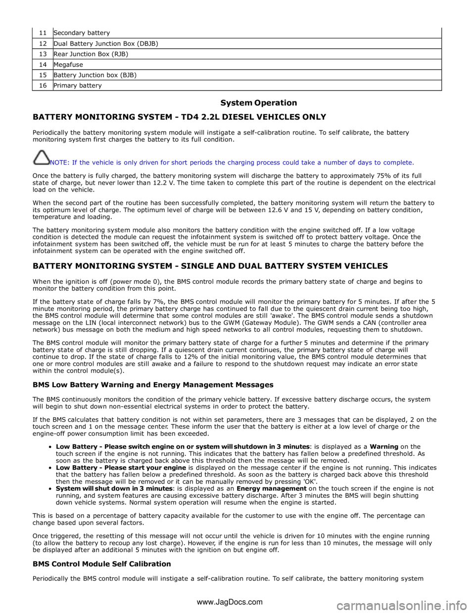
11 Secondary battery 12 Dual Battery Junction Box (DBJB) 13 Rear Junction Box (RJB) 14 Megafuse 15 Battery Junction box (BJB) 16 Primary battery
System Operation BATTERY MONITORING SYSTEM - TD4 2.2L DIESEL VEHICLES ONLY
Periodically the battery monitoring system module will instigate a self-calibration routine. To self calibrate, the battery
monitoring system first charges the battery to its full condition.
NOTE: If the vehicle is only driven for short periods the charging process could take a number of days to complete.
Once the battery is fully charged, the battery monitoring system will discharge the battery to approximately 75% of its full
state of charge, but never lower than 12.2 V. The time taken to complete this part of the routine is dependent on the electrical
load on the vehicle.
When the second part of the routine has been successfully completed, the battery monitoring system will return the battery to
its optimum level of charge. The optimum level of charge will be between 12.6 V and 15 V, depending on battery condition,
temperature and loading.
The battery monitoring system module also monitors the battery condition with the engine switched off. If a low voltage
condition is detected the module can request the infotainment system is switched off to protect battery voltage. Once the
infotainment system has been switched off, the vehicle must be run for at least 5 minutes to charge the battery before the
infotainment system can be operated with the engine switched off.
BATTERY MONITORING SYSTEM - SINGLE AND DUAL BATTERY SYSTEM VEHICLES
When the ignition is off (power mode 0), the BMS control module records the primary battery state of charge and begins to
monitor the battery condition from this point.
If the battery state of charge falls by 7%, the BMS control module will monitor the primary battery for 5 minutes. If after the 5
minute monitoring period, the primary battery charge has continued to fall due to the quiescent drain current being too high,
the BMS control module will determine that some control modules are still 'awake'. The BMS control module sends a shutdown
message on the LIN (local interconnect network) bus to the GWM (Gateway Module). The GWM sends a CAN (controller area
network) bus message on both the medium and high speed networks to all control modules, requesting them to shutdown.
The BMS control module will monitor the primary battery state of charge for a further 5 minutes and determine if the primary
battery state of charge is still dropping. If a quiescent drain current continues, the primary battery state of charge will
continue to drop. If the state of charge falls to 12% of the initial monitoring value, the BMS control module determines that
one or more control modules are still awake and a failure to respond to the shutdown request may indicate an error state
within the control module(s).
BMS Low Battery Warning and Energy Management Messages
The BMS continuously monitors the condition of the primary vehicle battery. If excessive battery discharge occurs, the system
will begin to shut down non-essential electrical systems in order to protect the battery.
If the BMS calculates that battery condition is not within set parameters, there are 3 messages that can be displayed, 2 on the
touch screen and 1 on the message center. These inform the user that the battery is either at a low level of charge or the
engine-off power consumption limit has been exceeded.
Low Battery - Please switch engine on or system will shutdown in 3 minutes: is displayed as a Warning on the
touch screen if the engine is not running. This indicates that the battery has fallen below a predefined threshold. As
soon as the battery is charged back above this threshold then the message will be removed.
Low Battery - Please start your engine is displayed on the message center if the engine is not running. This indicates
that the battery has fallen below a predefined threshold. As soon as the battery is charged back above this threshold
then the message will be removed or it can be manually removed by pressing 'OK'.
System will shut down in 3 minutes: is displayed as an Energy management on the touch screen if the engine is not
running, and system features are causing excessive battery discharge. After 3 minutes the BMS will begin shutting
down vehicle systems. Normal system operation will resume when the engine is started.
This is based on a percentage of battery capacity available for the customer to use with the engine off. The percentage can
change based upon several factors.
Once triggered, the resetting of this message will not occur until the vehicle is driven for 10 minutes with the engine running
(to allow the battery to recoup any lost charge). However, if the engine is run for less than 10 minutes, the message will only
be displayed after an additional 5 minutes with the ignition on but engine off.
BMS Control Module Self Calibration
Periodically the BMS control module will instigate a self-calibration routine. To self calibrate, the battery monitoring system www.JagDocs.com
Page 1898 of 3039
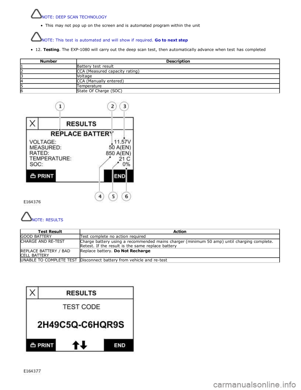
12.
Testing.
The
EXP-1080
will
carry
out
the
deep
scan
test,
then
automatically
advance
when test
has
completed
Number
Description 1
Battery
test
result 2
CCA
(Measured
capacity
rating) 3
Voltage 4
CCA
(Manually
entered) 5
Temperature 6
State
Of
Charge
(SOC)
NOTE:
RESULTS
Test
Result
Action GOOD
BATTERY
Test
complete
no
action required CHARGE
AND RE-TEST
Charge
battery
using a
recommended
mains
charger
(minimum 50 amp)
until
charging
complete.
Retest.
If
the
result
is
the
same replace battery REPLACE
BATTERY
/ BAD
CELL
BATTERY
Replace
battery.
Do
Not
Recharge UNABLE
TO
COMPLETE
TEST
Disconnect
battery
from
vehicle
and re-test
NOTE:DEEPSCANTECHNOLOGY
Thismaynotpop uponthescreen and isautomatedprogramwithin theunit
NOTE:Thistestisautomatedandwillshow ifrequired.Gotonextstep
Page 2014 of 3039
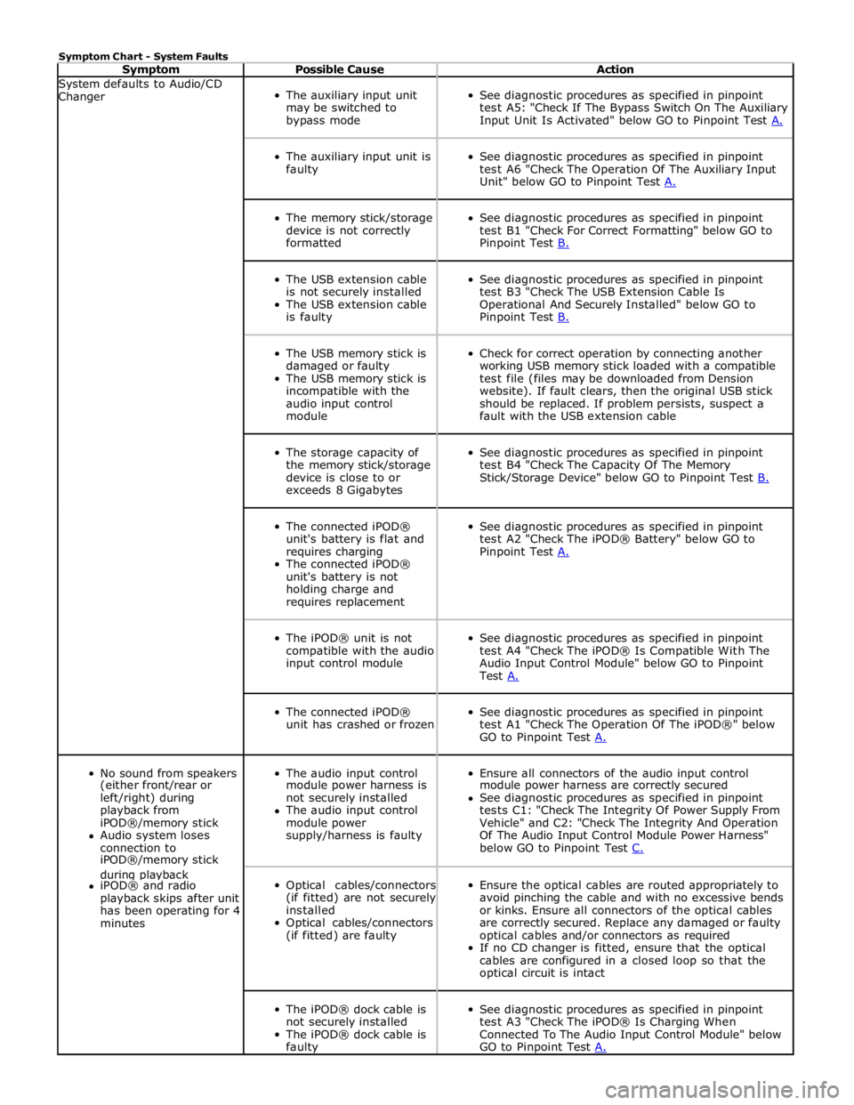
Symptom Chart - System Faults
Symptom Possible Cause Action System defaults to Audio/CD
Changer
The auxiliary input unit
may be switched to
bypass mode
See diagnostic procedures as specified in pinpoint
test A5: "Check If The Bypass Switch On The Auxiliary
Input Unit Is Activated" below GO to Pinpoint Test A.
The auxiliary input unit is
faulty
See diagnostic procedures as specified in pinpoint
test A6 "Check The Operation Of The Auxiliary Input
Unit" below GO to Pinpoint Test A.
The memory stick/storage
device is not correctly
formatted
See diagnostic procedures as specified in pinpoint
test B1 "Check For Correct Formatting" below GO to
Pinpoint Test B.
The USB extension cable
is not securely installed
The USB extension cable
is faulty
See diagnostic procedures as specified in pinpoint
test B3 "Check The USB Extension Cable Is
Operational And Securely Installed" below GO to
Pinpoint Test B.
The USB memory stick is
damaged or faulty
The USB memory stick is
incompatible with the
audio input control
module
Check for correct operation by connecting another
working USB memory stick loaded with a compatible
test file (files may be downloaded from Dension
website). If fault clears, then the original USB stick
should be replaced. If problem persists, suspect a
fault with the USB extension cable
The storage capacity of
the memory stick/storage
device is close to or
exceeds 8 Gigabytes
See diagnostic procedures as specified in pinpoint
test B4 "Check The Capacity Of The Memory
Stick/Storage Device" below GO to Pinpoint Test B.
The connected iPOD®
unit's battery is flat and
requires charging
The connected iPOD®
unit's battery is not
holding charge and
requires replacement
See diagnostic procedures as specified in pinpoint
test A2 "Check The iPOD® Battery" below GO to
Pinpoint Test A.
The iPOD® unit is not
compatible with the audio
input control module
See diagnostic procedures as specified in pinpoint
test A4 "Check The iPOD® Is Compatible With The
Audio Input Control Module" below GO to Pinpoint
Test A.
The connected iPOD®
unit has crashed or frozen
See diagnostic procedures as specified in pinpoint
test A1 "Check The Operation Of The iPOD®" below
GO to Pinpoint Test A.
No sound from speakers
The audio input control
Ensure all connectors of the audio input control (either front/rear or module power harness is module power harness are correctly secured left/right) during not securely installed See diagnostic procedures as specified in pinpoint playback from The audio input control tests C1: "Check The Integrity Of Power Supply From iPOD®/memory stick module power Vehicle" and C2: "Check The Integrity And Operation Audio system loses supply/harness is faulty Of The Audio Input Control Module Power Harness" connection to below GO to Pinpoint Test C. iPOD®/memory stick during playback
Optical cables/connectors
(if fitted) are not securely
installed
Optical cables/connectors
(if fitted) are faulty
Ensure the optical cables are routed appropriately to
avoid pinching the cable and with no excessive bends
or kinks. Ensure all connectors of the optical cables
are correctly secured. Replace any damaged or faulty
optical cables and/or connectors as required
If no CD changer is fitted, ensure that the optical
cables are configured in a closed loop so that the
optical circuit is intact iPOD® and radio playback skips after unit has been operating for 4 minutes
The iPOD® dock cable is
not securely installed
The iPOD® dock cable is
faulty
See diagnostic procedures as specified in pinpoint
test A3 "Check The iPOD® Is Charging When
Connected To The Audio Input Control Module" below
GO to Pinpoint Test A.
Page 2017 of 3039
Is the USB extension cable securely pushed into the USB connection port on the audio input control module
Yes
Replace the USB extension cable
No
Secure connections and retest B4: CHECK THE CAPACITY OF THE MEMORY STICK/STORAGE DEVICE
NOTE: The higher the capacity of the memory stick is the longer it takes to register with the audio input control module
and power up. The maximum permitted capacity is 8 Gigabytes 1 Check the storage capacity of the memory stick/storage device does not exceed 8 Gigabytes Is the storage capacity of the memory stick/storage device 8 Gigabytes or less?
Yes
High capacity devices may require longer to register and should be allowed up to two minutes to power up
following connection to the USB port. If memory stick fails to power up after two minutes, suspect a
faulty memory stick GO to B2. or USB extension cable GO to B3. No
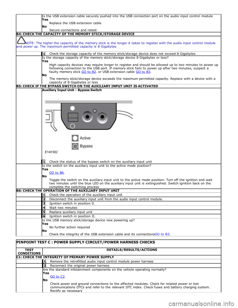
The memory stick/storage device exceeds the maximum permitted capacity. Replace with a device with a capacity of 8 Gigabytes or less B5: CHECK IF THE BYPASS SWITCH ON THE AUXILIARY INPUT UNIT IS ACTIVATED Auxiliary Input Unit - Bypass Switch
1 Check the status of the bypass switch on the auxiliary input unit Is the switch on the auxiliary input unit to the active mode position?
Yes
GO to B6. No
Toggle the switch on the auxiliary input unit to the active mode position. Turn off the ignition and wait
two minutes until the blue LED on the auxiliary input unit is extinguished. Switch ignition back on the complete the switching process B6: CHECK THE OPERATION OF THE AUXILIARY INPUT UNIT 1 Check the operation of the auxiliary input unit 2 Disconnect the auxiliary input unit from the audio input control module. 3 Ignition switch in position 0. 4 Wait two minutes 5 Replace auxiliary input unit 6 Ignition switch in position II. Is the USB memory stick/storage device now powering up?
Yes
No further action required
No
Check the integrity of the USB extension cable and its connectionsGO to B3.
PINPOINT TEST C : POWER SUPPLY CIRCUIT/POWER HARNESS CHECKS TEST
CONDITIONS DETAILS/RESULTS/ACTIONS C1: CHECK THE INTEGRITY OF PRIMARY POWER SUPPLY 1 Remove the retrofitted audio input control module power harness 2 Reconnect the original power harness Are the standard infotainment components on the vehicle operating normally?
Yes
GO to C2. No
Check power and ground connections to the affected modules. Check for related power or lost
communications DTCs and refer to the relevant DTC index. Check fuses and battery charging system. Rectify as necessary