brake light JAGUAR XFR 2010 1.G Workshop Manual
[x] Cancel search | Manufacturer: JAGUAR, Model Year: 2010, Model line: XFR, Model: JAGUAR XFR 2010 1.GPages: 3039, PDF Size: 58.49 MB
Page 103 of 3039
General Information - Road/Roller Testing
Description and Operation Published: 11-May-2011
Road or roller testing may be carried out for various reasons and a procedure detailing pre-test checks, through engine starting
and stopping, pre-driving checks, on-test checks to final checks on completion of the test is given in this section.
Unless complete vehicle performance is being checked, the full road test procedure need not be carried out. Instead, those
items particularly relevant to the system/s being checked can be extracted.
Pre - Test Checks
WARNING: If the brake system hydraulic fluid level is low, pedal travel is excessive or a hydraulic leak is found, do not
attempt to road test the vehicle until the reason for the low fluid level, excessive pedal travel or hydraulic leak is found and
rectified.
It is suggested that pre-test checks, and functional tests of those systems/circuits which affect the safe and legal operations
of the vehicle, such as brakes, lights and steering, should always be carried out before the road or roller test.
Engine oil level
Engine coolant level
Tires, for correct pressure, compatible types and tread patterns, and wear within limits
There is sufficient fuel in the tank to complete the test
All around the engine, transmission and under the vehicle for oil, coolant, hydraulic and fuel leaks. Make a note of any
apparent leaks and wipe off the surrounding areas to make it easier to identify the extent of the leak on completion of
the test
Starting the Engine
CAUTION: On initial drive away from cold and within the first 1.5 km (1 mile), do not depress accelerator pedal beyond
half travel until the vehicle has attained a minimum speed of 25 km/h (15 miles/h). Never operate at high engine speed or
with the accelerator pedal at full travel whilst the engine is cold.
With the ignition switched off, check:
The parking brake is applied
The transmission selector lever is in Park
All instrument gauges (except fuel gauge) read zero
With the ignition switched on, check:
Ignition controlled warning lamps come on
Engine coolant temperature gauge registers a reading compatible with the engine coolant temperature
Fuel gauge registers a reading appropriate to the fuel level in the tank
The operation of the parking brake and brake fluid level warning lamps
On Road or Roller Test Check:
CAUTION: If road testing, check the brake operation while still travelling at low speed before continuing with the test. If
the brakes pull to one side, or appear to be otherwise faulty, do not continue with the road test until the fault has been found
and rectified.
Initial gear engagement is smooth
Parking brake control operates smoothly and the parking brake releases quickly and completely
Transmission takes up the drive smoothly, without judder
The engine power output is satisfactory, full power is achieved, acceleration is smooth and pedal operation not stiff or
heavy, and engine speed returns to idle correctly
There is no excessive or abnormally colored smoke from the engine under normal driving, heavy load or overrun
conditions
Steering operation, including power steering, is smooth, accurate, not excessively heavy or with excessive free play or
vibration. Does not pull to one side and self centres smoothly after cornering
Speedometer, oil pressure warning lamp, coolant temperature gauge and tachometer register the correct readings or
operate correctly
Switches and controls operate smoothly and positively, warning lamps operate correctly and the direction indicator
control self cancels when the steering is returned to the straight ahead position
Heating and ventilation systems work correctly and effectively
Brake operation and efficiency
Brake Testing
WARNING: When brake testing, avoid breathing the smoke or fumes from hot brakes, this may contain asbestos dust
which is hazardous to health, see Health and Safety Precautions.
Page 104 of 3039

Avoid brake testing on busy roads where it can cause inconvenience or danger to other road users.
CAUTION: Brake testing which includes heavy brake applications should not be carried out with new brake pads/discs or
linings/drums until the components have bedded-in. New brake friction components will not reach full efficiency until the
bedding-in process is complete.
Test the brakes at several speeds within the normal operating range using both light and heavy pedal pressure. Note any
tendency to snatch, pull or drag, and any undue delay in application or release.
Allow the vehicle to coast and note any tendency to pull to one side, or evidence that the brakes are binding.
After stopping the vehicle (not immediately after a period of heavy braking), carefully check the brake temperature. A disc
which feels hot, or appreciably hotter than the others, indicates that the brake is binding.
After completion of the test, check for:
Oil, coolant, hydraulic, air and fuel leaks
Abnormal temperature of any moving components or assemblies, e.g. wheel hubs, transmission, axle etc., which might
indicate over tightness or lack of lubrication
Page 185 of 3039
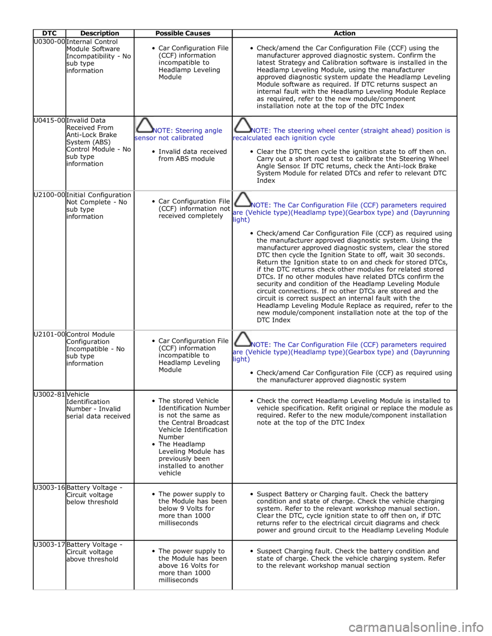
DTC Description Possible Causes Action U0300-00
Internal Control
Module Software
Incompatibility - No
sub type
information
Car Configuration File
(CCF) information
incompatible to
Headlamp Leveling
Module
Check/amend the Car Configuration File (CCF) using the
manufacturer approved diagnostic system. Confirm the
latest Strategy and Calibration software is installed in the
Headlamp Leveling Module, using the manufacturer
approved diagnostic system update the Headlamp Leveling
Module software as required. If DTC returns suspect an
internal fault with the Headlamp Leveling Module Replace
as required, refer to the new module/component
installation note at the top of the DTC Index U0415-00
Invalid Data
Received From
Anti-Lock Brake
System (ABS)
Control Module - No
sub type
information
NOTE: Steering angle
sensor not calibrated
Invalid data received
from ABS module
NOTE: The steering wheel center (straight ahead) position is
recalculated each ignition cycle
Clear the DTC then cycle the ignition state to off then on.
Carry out a short road test to calibrate the Steering Wheel
Angle Sensor. If DTC returns, check the Anti-lock Brake
System Module for related DTCs and refer to relevant DTC
Index U2100-00
Initial Configuration
Not Complete - No
sub type
information
Car Configuration File
(CCF) information not
received completely
NOTE: The Car Configuration File (CCF) parameters required
are (Vehicle type)(Headlamp type)(Gearbox type) and (Dayrunning
light)
Check/amend Car Configuration File (CCF) as required using
the manufacturer approved diagnostic system. Using the
manufacturer approved diagnostic system, clear the stored
DTC then cycle the Ignition State to off, wait 30 seconds.
Return the Ignition state to on and check for stored DTCs,
if the DTC returns check other modules for related stored
DTCs. If no other modules have related DTCs confirm the
security and condition of the Headlamp Leveling Module
circuit connections. If no other DTCs are stored and the
circuit is correct suspect an internal fault with the
Headlamp Leveling Module Replace as required, refer to the
new module/component installation note at the top of the
DTC Index U2101-00
Control Module
Configuration
Incompatible - No
sub type
information
Car Configuration File
(CCF) information
incompatible to
Headlamp Leveling
Module
NOTE: The Car Configuration File (CCF) parameters required
are (Vehicle type)(Headlamp type)(Gearbox type) and (Dayrunning
light)
Check/amend Car Configuration File (CCF) as required using
the manufacturer approved diagnostic system U3002-81
Vehicle
Identification
Number - Invalid
serial data received
The stored Vehicle
Identification Number
is not the same as
the Central Broadcast
Vehicle Identification
Number
The Headlamp
Leveling Module has
previously been
installed to another
vehicle
Check the correct Headlamp Leveling Module is installed to
vehicle specification. Refit original or replace the module as
required. Refer to the new module/component installation
note at the top of the DTC Index U3003-16
Battery Voltage -
Circuit voltage
below threshold
The power supply to
the Module has been
below 9 Volts for
more than 1000
milliseconds
Suspect Battery or Charging fault. Check the battery
condition and state of charge. Check the vehicle charging
system. Refer to the relevant workshop manual section.
Clear the DTC, cycle ignition state to off then on, if DTC
returns refer to the electrical circuit diagrams and check
power and ground circuit to the Headlamp Leveling Module U3003-17
Battery Voltage -
Circuit voltage
above threshold
The power supply to
the Module has been
above 16 Volts for
more than 1000
milliseconds
Suspect Charging fault. Check the battery condition and
state of charge. Check the vehicle charging system. Refer
to the relevant workshop manual section
Page 300 of 3039
Noise Conditions
Gear noise is typically a howling or whining due to gear damage or incorrect bearing preload. It can occur at various
speeds and driving conditions, or it can be continuous
Chuckle is a particular rattling noise that sounds like a stick against the spokes of a spinning bicycle wheel. It occurs
while decelerating from approximately 64 km/h (40 miles/h) and can usually be heard all the way to a stop. The
frequency varies with vehicle speed
Knock is very similar to chuckle, though it may be louder and occurs on acceleration or deceleration. The tear down will
disclose what has to be corrected
Check and rule out tires, exhaust and trim items before disassembling the transmission to diagnose and correct gear noise.
The noises described under Road Test usually have specific causes that can be diagnosed by observation as the unit is
disassembled. The initial clues are the type of noise heard on the road test and the driving conditions.
Vibration Conditions
wear. NOTE: New Constant Velocity (CV) joints should not be installed unless disassembly and inspection revealed unusual
Clicking, popping or grinding noises may be caused by the following:
Cut or damaged CV joint boots resulting in inadequate or contaminated lubricant in the outboard or inboard CV joint
bearing housings
Loose CV joint boot clamps
Another component contacting the rear drive half shaft
Worn, damaged or incorrectly installed wheel bearing, suspension or brake component
Vibration at highway speeds may be caused by the following:
Out-of-balance front or rear wheels
Out-of-round tires
Driveline imbalance
Driveline run-out (alignment)
NOTE: Rear drive half shafts are not balanced and are not likely to contribute to rotational vibration disturbance.
Shudder or vibration during acceleration (including from rest) may be caused by the following:
Driveline alignment
Excessively worn or damaged outboard or inboard CV joint bearing housing
Excessively high CV joint operating angles caused by incorrect ride height. Check ride height, verify correct spring rate
and check items under Inoperative Conditions
Excessively worn driveshaft components
Leakage Conditions
1. Inspect the CV joint boots for evidence of cracks, tears or splits.
2. Inspect the underbody for any indication of grease splatter in the vicinity of the rear drive half shaft, outboard and
inboard CV joint boot locations, which is an indication of CV joint boot or CV joint boot clamp damage.
3. Inspect the inboard CV joint bearing housing seal for leakage.
Inoperative Conditions
If a CV joint or rear drive half shaft pull-out occurs, check the following:
suspension components for correct location, damage or wear
bushings for wear
subframe for damage
bent or worn components
- Stabilizer bar link
- Left-hand rear suspension lower arm and bushing
- Right-hand rear suspension lower arm and bushing
- Rear wheel hub and rear drive half shaft
Road Test
A gear-driven unit will produce a certain amount of noise. Some noise is acceptable and may be audible at certain speeds or
under various driving conditions as on a newly paved blacktop road. The slight noise is in no way detrimental and must be
considered normal.
The road test and customer interview (if available) provide information needed to identify the condition and give direction to
the correct starting point for diagnosis.
1. Make notes throughout the diagnosis routine. Make sure to write down even the smallest piece of information, because
Page 301 of 3039

it may turn out to be the most important.
2. Do not touch anything until a road test and a thorough visual inspection of the vehicle have been carried out. Leave the
tire pressures and vehicle load just where they were when the condition was first observed. Adjusting tire pressures,
vehicle load or making other adjustments may reduce the conditions intensity to a point where it cannot be identified
clearly. It may also inject something new into the system, preventing correct diagnosis.
3. Make a visual inspection as part of the preliminary diagnosis routine, writing down anything that does not look right.
Note tire pressures, but do not adjust them yet. Note leaking fluids, loose nuts and bolts, or bright spots where
components may be rubbing against each other. Check the luggage compartment for unusual loads.
4. Road test the vehicle and define the condition by reproducing it several times during the road test.
5. Carry out the Road Test Quick Checks as soon as the condition is reproduced. This will identify the correct diagnostic
procedure. Carry out the Road Test Quick Checks more than once to verify they are providing a valid result. Remember,
the Road Test Quick Checks may not tell where the concern is, but they will tell where it is not.
Road Test Quick Checks
1. 24-80 km/h (15-50 miles/h): With light acceleration, a moaning noise is heard and possibly a vibration is felt in the
front floor pan. It is usually worse at a particular engine speed and at a particular throttle setting during acceleration at
that speed. It may also produce a moaning sound, depending on what component is causing it. Refer to Tip-In Moan in
the Symptom Chart.
2. Acceleration/deceleration: With slow acceleration and deceleration, a shake is sometimes noticed in the steering
wheel/column, seats, front floor pan, front door trim panel or front end sheet metal. It is a low frequency vibration
(around 9-15 cycles per second). It may or may not be increased by applying brakes lightly. Refer to Idle Boom/Shake
/Vibration in the Symptom Chart.
3. High speed: A vibration is felt in the front floor pan or seats with no visible shake, but with an accompanying sound or
rumble, buzz, hum, drone or booming noise. Coast with the clutch pedal depressed or shift control selector lever in
neutral and engine idling. If vibration is still evident, it may be related to wheels, tires, front brake discs, wheel hubs
or front wheel bearings. Refer to High Speed Shake in the Symptom Chart.
4. Engine rpm sensitive: A vibration is felt whenever the engine reaches a particular rpm. It will disappear in neutral
coasts. The vibration can be duplicated by operating the engine at the problem rpm while the vehicle is stationary. It
can be caused by any component, from the accessory drive belt to the torque converter which turns at engine speed
when the vehicle is stopped. Refer to High Speed Shake in the Symptom Chart.
5. Noise/vibration while turning: Clicking, popping, or grinding noises may be due to a worn, damaged, or incorrectly
installed front wheel bearing, rear drive half shaft or CV joint.
6. Noise/vibration that is road speed relative: This noise/vibration can be diagnosed independent of engine speed or gear
selected (engine speed varies but torque and road speed remain constant). The cause may be a rear drive
axle/differential whine.
Road Conditions
An experienced technician will always establish a route that will be used for all NVH diagnosis road tests. The road selected
should be reasonably smooth, level and free of undulations (unless a particular condition needs to be identified). A smooth
asphalt road that allows driving over a range of speeds is best. Gravel or bumpy roads are unsuitable because of the additional
road noise produced. Once the route is established and consistently used, the road noise variable is eliminated from the test
results.
NOTE: Some concerns may be apparent only on smooth asphalt roads.
If a customer complains of a noise or vibration on a particular road and only on a particular road, the source of the concern
may be the road surface. If possible, try to test the vehicle on the same type of road.
Vehicle Preparation
Carry out a thorough visual inspection of the vehicle before carrying out the road test. Note anything which is unusual. Do not
repair or adjust any condition until the road test is carried out, unless the vehicle is inoperative or the condition could pose a
hazard to the technician.
After verifying the condition has been corrected, make sure all components removed have been installed.
Lift Test
After a road test, it is sometimes useful to do a similar test on a lift.
When carrying out the high-speed shake diagnosis or engine accessory vibration diagnosis on a lift, observe the following
precautions:
WARNING: If only one drive wheel is allowed to rotate, speed must be limited to 55 km/h (35 miles/h) indicated on the
speedometer since actual wheel speed will be twice that indicated on the speedometer. Speed exceeding 55 km/h (35 miles/h)
or allowing the drive wheel to hang unsupported could result in tire disintegration, differential failure, constant velocity joint
Page 332 of 3039

Upper Control Arm
The forged-aluminum upper control arm is a wishbone design and connects to the vehicle body through two plain bushes, and
links to the swan neck wheel knuckle by an integral ball joint. The upper control arm is inclined to provide anti-dive
characteristics under heavy braking, while also controlling geometry for vehicle straight-line stability.
Lower Control Arm
The forged aluminum lower control arms are of the wishbone design; the arms separate to allow for optimum bush tuning:
The rear lateral control arm is fitted with a bush at its inner end which locates between brackets on the subframe. The
arm is secured with an eccentric bolt which provides the adjustment of the suspension camber geometry. The outer end
of the control arm has a tapered hole which locates on a ball joint fitted to the wheel knuckle. An integral clevis bracket
on the forward face of the lateral control arm allows for the attachment of the forward control arm. A bush is fitted
below the clevis bracket to provide for the attachment of the stabilizer bar link. A cross-axis joint is fitted to a
cross-hole in the control arm to provide the location for the clevis attachment of the spring and damper assembly.
The forward control arm is fitted with a fluid-block rubber bush at its inner end which locates between brackets on the
subframe. The arm is secured with an eccentric bolt which provides adjustment of the castor and camber geometry. The
outer end of the control arm is fitted with a cross-axis joint and locates in the integral clevis bracket on the lateral
control arm.
Wheel Knuckle
The cast aluminum wheel knuckle is a swan neck design and attaches to the upper control arm and lower lateral control arm.
The lower lateral control arm locates on a non serviceable ball-joint integral with the wheel knuckle. The lower boss on the
rear of the knuckle provides for the attachment of the steering gear tie-rod ball joint.
The wheel knuckle also provides the mounting locations for the:
wheel hub and bearing assembly
the wheel speed sensor (integral to the wheel hub and bearing assembly)
brake caliper and disc shield.
Stabilizer Bar
The stabilizer bar is attached to the front of the subframe with bushes and mounting brackets. The pressed steel mounting
brackets locate over the bushes and are attached to the cross member with bolts screwed into threaded locations in the
subframe. The stabilizer bar has crimped, 'anti-shuffle' collars pressed in position on the inside edges of the bushes. The
collars prevent sideways movement of the stabilizer bar.
The stabilizer bar is manufactured from 32mm diameter tubular steel on supercharged models and 31mm diameter tubular
steel on diesel and normally aspirated models and has been designed to provide particular characteristics in maintaining roll
rates, specifically in primary ride comfort.
Each end of the stabilizer bar curves rearwards to attach to a ball joint on a stabilizer link. Each stabilizer link is secured to a
bush in the lower lateral arm with a bolt and locknut. The links allow the stabilizer bar to move with the wheel travel providing
maximum effectiveness.
The only difference between the front stabilizer bars, in addition to the diameter, is in the shape to accommodate engine
variant:
a slightly curved bar, between bush centers, for V6 diesel (31 mm dia) and V8 gasoline supercharged (32 mm dia),
a straight bar, between bush centers, for V6 and V8 normally aspirated gasoline engines (31 mm dia).
Spring and Damper Assembly
The spring and damper assemblies are located between the lower lateral arm and the front suspension housing in the inner
wing. Dependant on vehicle model there are three types of coil spring and damper available:
a standard oil passive damper (All models except supercharged),
an adaptive damper, also known as Computer Active Technology Suspension (CATS) on 4.2L supercharged vehicles up to
2010MY, For additional information refer to Vehicle Dynamic Suspension 4.2L.
a continuously variable adaptive damper, also known as Adaptive Dynamics System on 5.0L supercharged vehicles from
2010MY. For additional information refer to Vehicle Dynamic Suspension 5.0L.
The dampers are a monotube design with a spring seat secured by a circlip onto the damper tube. The damper's lower
spherical joint is an integral part of the lateral lower control-arm, and the damper takes the form of a clevis-end, which
straddles the spherical joint.
The damper piston is connected to a damper rod which is sealed at its exit point from the damper body. The threaded outer
end of the damper rod locates through a hole in the top mount. A self locking nut secures the top mount to the damper rod.
The damper rod on the adaptive damper has an electrical connector on the outer end of the damper rod.
Supercharged 4.2L vehicles up to 2010MY: The adaptive damper functions by restricting the flow of hydraulic fluid through
internal galleries in the damper's piston. The adaptive damper has a solenoid operated valve, which when switched allows a
greater flow of hydraulic fluid through the damper's piston. This provides a softer damping characteristic from the damper. The
adaptive damper defaults to a firmer setting when not activated. The solenoid is computer controlled and can switch between
soft and hard damping settings depending on road wheel inputs and vehicle speed.
Supercharged 5.0L vehicles from 2010MY: The variable damper functions by adjustment of a solenoid operated variable orifice,
which opens up an alternative path for oil flow within the damper. When de-energized the bypass is closed and all the oil flows
Page 582 of 3039
Brake System - General Information - Brake System
Diagnosis and Testing
Principle of Operation Published: 11-May-2011
For a detailed description of the brake system, refer to the relevant Description and Operation sections in the workshop
manual. REFER to:
Front Disc Brake (206-03, Description and Operation),
Front Disc Brake (206-03, Description and Operation),
Front Disc Brake (206-03, Description and Operation),
Rear Disc Brake (206-04, Description and Operation),
Rear Disc Brake (206-04, Description and Operation),
Rear Disc Brake (206-04, Description and Operation),
Parking Brake (206-05 Parking Brake and Actuation, Description and Operation), Parking Brake (206-05 Parking Brake and Actuation, Description and Operation), Parking Brake (206-05 Parking Brake and Actuation, Description and Operation), Hydraulic Brake Actuation (206-06 Hydraulic Brake Actuation, Description and Operation), Hydraulic Brake Actuation (206-06 Hydraulic Brake Actuation, Description and Operation), Hydraulic Brake Actuation (206-06 Hydraulic Brake Actuation, Description and Operation), Brake Booster (206-07 Power Brake Actuation, Description and Operation), Brake Booster (206-07 Power Brake Actuation, Description and Operation), Brake Booster (206-07, Description and Operation).
Inspection and Verification
Visually examine the front and rear wheel and tire assemblies for damage such as uneven wear patterns, tread worn out or
sidewall damage. Verify the tires are the same size, type and, where possible, same manufacturer. Replace the damaged
wheel or excessively worn tire.
Wheels and tires must be cleared of any foreign matter and tire pressures adjusted to the correct specification.
If the tires exhibit uneven wear or feathering, the cause must be corrected. Check the steering and suspension components for
damage or wear and, if necessary, check and adjust front wheel alignment. REFER to: (204-00 Suspension System - General
Information)
Specifications (Specifications), Front Toe Adjustment (General Procedures).
Visual Inspection
Mechanical Electrical
Brake master cylinder
Brake caliper piston(s)
Brake discs
Wheel bearings
Brake pads
Power brake booster
Brake pedal linkage
Brake booster vacuum hose
Tires
Debris
Parking brake actuator
Parking brake module
Parking brake switch
Damaged or corroded wiring harness
Brake master cylinder fluid level switch Road Test
Carry out a road test to compare actual vehicle braking performance with the performance standards expected by the driver.
The ability of the test driver to make valid comparisons and detect performance deficiencies will depend on experience.
The driver should have a thorough knowledge of brake system operation and accepted general performance guidelines to make
good comparisons and detect performance concerns.
An experienced brake technician will always establish a route that will be used for all brake diagnosis road tests. The roads
selected will be reasonably smooth and level. Gravel or bumpy roads are not suitable because the surface does not allow the
tires to grip the road equally. Crowned roads should be avoided because of the large amount of weight shifted to the low set
of wheels on this type of road. Once the route is established and consistently used, the road surface variable can be
eliminated from the test results.
Before a road test, obtain a complete description of the customer concerns or suspected condition. From the description, the
technician's experience will allow the technician to match possible causes with symptoms. Certain components will be tagged
as possible suspects while others will be eliminated by the evidence. More importantly, the customer description can reveal
unsafe conditions which should be checked or corrected before the road test. The description will also help form the basic
approach to the road test by narrowing the concern to specific components, vehicle speed or conditions.
Begin the road test with a general brake performance check. Keeping the description of the concern in mind, test the brakes at
different vehicle speeds using both light and heavy pedal pressure. To determine if the concern is in the front or rear braking
system, use the brake pedal and then use the parking brake control. If the condition (pull, vibration, pulsation) occurs only
with the parking brake, the concern is in the rear brake system.
Page 583 of 3039
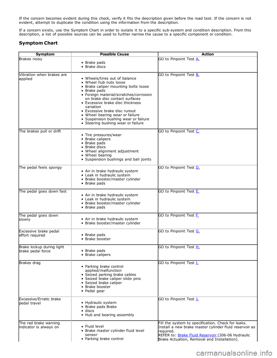
If the concern becomes evident during this check, verify it fits the description given before the road test. If the concern is not
evident, attempt to duplicate the condition using the information from the description.
If a concern exists, use the Symptom Chart in order to isolate it to a specific sub-system and condition description. From this
description, a list of possible sources can be used to further narrow the cause to a specific component or condition.
Symptom Chart
Symptom Possible Cause Action Brakes noisy
Brake pads
Brake discs GO to Pinpoint Test A. Vibration when brakes are
applied
Wheels/tires out of balance
Wheel hub nuts loose
Brake caliper mounting bolts loose
Brake pads
Foreign material/scratches/corrosion
on brake disc contact surfaces
Excessive brake disc thickness
variation
Excessive brake disc runout
Wheel bearing wear or failure
Suspension bushing wear or failure
Steering bushing wear or failure GO to Pinpoint Test B. The brakes pull or drift
Tire pressures/wear
Brake calipers
Brake pads
Brake discs
Wheel alignment adjustment
Wheel bearing
Suspension bushings and ball joints GO to Pinpoint Test C. The pedal feels spongy
Air in brake hydraulic system
Leak in hydraulic system
Brake booster/master cylinder
Brake pads GO to Pinpoint Test D. The pedal goes down fast
Air in brake hydraulic system
Leak in hydraulic system
Brake booster/master cylinder
Brake pads GO to Pinpoint Test E. The pedal goes down
slowly
Air in brake hydraulic system
Brake booster/master cylinder GO to Pinpoint Test F. Excessive brake pedal
effort required
Brake pads
Brake booster GO to Pinpoint Test G. Brake lockup during light
brake pedal force
Brake pads
Brake calipers GO to Pinpoint Test H. Brakes drag
Parking brake control
applied/malfunction
Seized parking brake cables
Seized brake caliper slide pins
Seized brake caliper
Brake booster
Pedal gear GO to Pinpoint Test I. Excessive/Erratic brake
pedal travel
Hydraulic system
Brake pads Brake
discs
Hub and bearing assembly GO to Pinpoint Test J. The red brake warning
indicator is always on
Fluid level
Brake master cylinder fluid level
sensor
Parking brake control Fill the system to specification. Check for leaks.
Install a new brake master cylinder fluid reservoir as
required.
REFER to: Brake Fluid Reservoir (206-06 Hydraulic Brake Actuation, Removal and Installation).
Page 584 of 3039
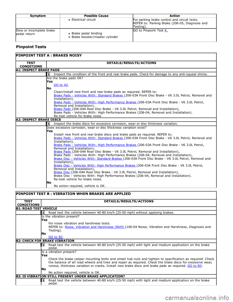
Symptom Possible Cause Action Electrical circuit
For parking brake control and circuit tests.
REFER to: Parking Brake (206-05, Diagnosis and Testing). Slow or incomplete brake
pedal return
Brake pedal binding
Brake booster/master cylinder GO to Pinpoint Test K. Pinpoint Tests
PINPOINT TEST A : BRAKES NOISY TEST
CONDITIONS DETAILS/RESULTS/ACTIONS A1: INSPECT BRAKE PADS 1 Inspect the condition of the front and rear brake pads. Check for damage to any anti-squeal shims. Are the brake pads OK? Yes
GO to A2. No
Clean/install new front and rear brake pads as required. REFER to:
Brake Pads - Vehicles With: Standard Brakes (206-03A Front Disc Brake - V6 3.0L Petrol, Removal and Installation),
Brake Pads - Vehicles With: High Performance Brakes (206-03A Front Disc Brake - V6 3.0L Petrol, Removal and Installation),
Brake Pads (206-04A Rear Disc Brake - V6 3.0L Petrol, Removal and Installation), Brake Pads - Vehicles With: High Performance Brakes (206-04, Removal and Installation).
Re-test vehicle for brake noise. A2: INSPECT BRAKE DISCS 1 Inspect the brake discs for excessive corrosion, wear or disc thickness variation. Does excessive corrosion, wear or disc thickness variation exist? Yes
Install new front and rear brake discs and brake pads as required. REFER to:
Brake Pads - Vehicles With: Standard Brakes (206-03A Front Disc Brake - V6 3.0L Petrol, Removal and Installation),
Brake Pads - Vehicles With: High Performance Brakes (206-03A Front Disc Brake - V6 3.0L Petrol, Removal and Installation),
Brake Pads (206-04A Rear Disc Brake - V6 3.0L Petrol, Removal and Installation), Brake Pads - Vehicles With: High Performance Brakes (206-04, Removal and Installation),
Brake Disc - Vehicles With: Standard Brakes (206-03A Front Disc Brake - V6 3.0L Petrol, Removal and Installation),
Brake Disc - Vehicles With: High Performance Brakes (206-03A Front Disc Brake - V6 3.0L Petrol, Removal and Installation),
Brake Disc (206-04A Rear Disc Brake - V6 3.0L Petrol, Removal and Installation), Brake Disc - Vehicles With: High Performance Brakes (206-04, Removal and Installation).
Re-test vehicle for brake noise.
No
No action required, vehicle is OK.
PINPOINT TEST B : VIBRATION WHEN BRAKES ARE APPLIED TEST
CONDITIONS DETAILS/RESULTS/ACTIONS B1: ROAD TEST VEHICLE 1 Road test the vehicle between 40-80 km/h (25-50 mph) without applying brakes. Is the vibration present?
Yes
For noise vibration and harshness tests.
REFER to: Noise, Vibration and Harshness (NVH) (100-04 Noise, Vibration and Harshness, Diagnosis and Testing).
No
GO to B2. B2: CHECK FOR BRAKE VIBRATION 1 Road test the vehicle between 40-80 km/h (25-50 mph) with light and medium application on the brake pedal. Is a vibration present?
Yes
Check the brake caliper mounting bolts and wheel hub nuts and tighten to specification as required. Check
the balance of all road wheels and tires and repair as required. Check the brake discs for excessive wear,
runout, thickness variation or cracks. Install new brake discs and brake pads as required. GO to B3. No
No action required, vehicle is OK. B3: IS VIBRATION STILL PRESENT UNDER BRAKE APPLICATION? 1 Road test the vehicle between 40-80 km/h (25-50 mph) with light and medium application on the brake pedal.
Page 586 of 3039
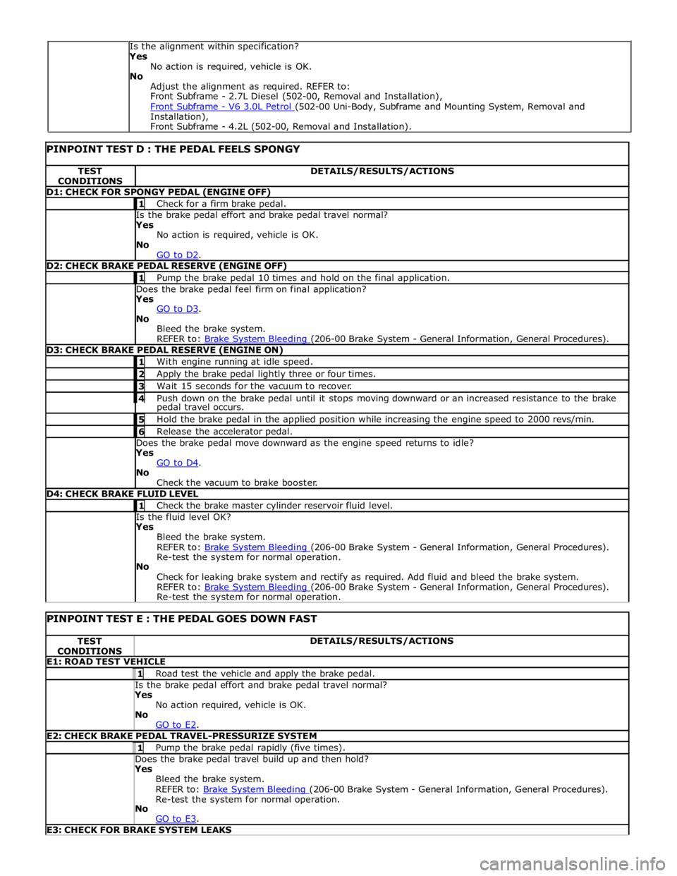
TEST
CONDITIONS DETAILS/RESULTS/ACTIONS D1: CHECK FOR SPONGY PEDAL (ENGINE OFF) 1 Check for a firm brake pedal. Is the brake pedal effort and brake pedal travel normal? Yes
No action is required, vehicle is OK.
No
GO to D2. D2: CHECK BRAKE PEDAL RESERVE (ENGINE OFF) 1 Pump the brake pedal 10 times and hold on the final application. Does the brake pedal feel firm on final application? Yes
GO to D3. No
Bleed the brake system.
REFER to: Brake System Bleeding (206-00 Brake System - General Information, General Procedures). D3: CHECK BRAKE PEDAL RESERVE (ENGINE ON) 1 With engine running at idle speed. 2 Apply the brake pedal lightly three or four times. 3 Wait 15 seconds for the vacuum to recover. 4 Push down on the brake pedal until it stops moving downward or an increased resistance to the brake pedal travel occurs. 5 Hold the brake pedal in the applied position while increasing the engine speed to 2000 revs/min. 6 Release the accelerator pedal. Does the brake pedal move downward as the engine speed returns to idle? Yes
GO to D4. No
Check the vacuum to brake booster. D4: CHECK BRAKE FLUID LEVEL 1 Check the brake master cylinder reservoir fluid level. Is the fluid level OK? Yes
Bleed the brake system.
REFER to: Brake System Bleeding (206-00 Brake System - General Information, General Procedures). Re-test the system for normal operation.
No
Check for leaking brake system and rectify as required. Add fluid and bleed the brake system.
REFER to: Brake System Bleeding (206-00 Brake System - General Information, General Procedures). Re-test the system for normal operation.
PINPOINT TEST E : THE PEDAL GOES DOWN FAST TEST
CONDITIONS DETAILS/RESULTS/ACTIONS E1: ROAD TEST VEHICLE 1 Road test the vehicle and apply the brake pedal. Is the brake pedal effort and brake pedal travel normal? Yes
No action required, vehicle is OK.
No
GO to E2. E2: CHECK BRAKE PEDAL TRAVEL-PRESSURIZE SYSTEM 1 Pump the brake pedal rapidly (five times). Does the brake pedal travel build up and then hold? Yes
Bleed the brake system.
REFER to: Brake System Bleeding (206-00 Brake System - General Information, General Procedures). Re-test the system for normal operation.
No
GO to E3. E3: CHECK FOR BRAKE SYSTEM LEAKS Is the alignment within specification?
Yes
No action is required, vehicle is OK.
No
Adjust the alignment as required. REFER to:
Front Subframe - 2.7L Diesel (502-00, Removal and Installation),
Front Subframe - V6 3.0L Petrol (502-00 Uni-Body, Subframe and Mounting System, Removal and Installation),
Front Subframe - 4.2L (502-00, Removal and Installation).