change key battery JAGUAR XFR 2010 1.G Workshop Manual
[x] Cancel search | Manufacturer: JAGUAR, Model Year: 2010, Model line: XFR, Model: JAGUAR XFR 2010 1.GPages: 3039, PDF Size: 58.49 MB
Page 49 of 3039
General Information - General Service Information
Description and Operation
Repairs and Replacements Published: 28-Dec-2012
When service parts are required, it is essential that only genuine Jaguar/Daimler replacements are used.
Attention is drawn to the following points concerning repairs and the installation of replacement parts and accessories:
Safety features embodied in the vehicle may be impaired if other than genuine parts are installed. In certain territories,
legislation prohibits the installation of parts which are not produced to the vehicle manufacturer's specification.
Torque wrench setting figures given in this manual must be strictly adhered to. Locking devices, where specified, must
be installed. If the efficiency of a locking device is impaired during removal it must be renewed.
Owners purchasing accessories while travelling abroad should make sure that the accessory and its installed location on
the vehicle conform to mandatory requirements existing in their country of origin.
The vehicle warranty may be invalidated by the installation of other than genuine Jaguar/Daimler parts. All
Jaguar/Daimler replacements have the full backing of the factory warranty.
Jaguar/Daimler dealers are obliged to supply only genuine service parts.
Vehicle Specifications
Purchasers are advised that the specification details set out in this manual apply to a range of vehicles and not to any specific
one. For the specification of a particular vehicle, purchasers should consult their dealer.
The Manufacturer reserves the right to vary the specifications, with or without notice, and at such times and in such manner as
the Manufacturer thinks fit. Major as well as minor changes may be involved, in accordance with the Manufacturer's policy of
continuous improvement.
Whilst every effort is made to make sure the accuracy of the particulars contained in this manual, neither the Manufacturer nor
the Dealer, by whom the manual is supplied, shall in any circumstances be held liable for any inaccuracy or the consequences
thereof.
Service Repair Operation Numbering
A master index of numbered operations has been compiled for universal application to all vehicles manufactured by Jaguar
Land Rover Limited.
Each operation is allocated a number from the master index and cross-refers with an identical number in the Repair Operation
Times schedule. The number consists of six digits arranged in three pairs.
Each maintenance procedure in this manual is described in the sequence necessary to complete the operation in the minimum
time, as specified in the Repair Operation Times schedule.
References to Bank-1 and Bank-2
References to Bank-1 and Bank-2 are made with regard to the engine. When viewed from the flywheel the right-hand bank will
be Bank-1 and the left-hand bank will be Bank-2.
Special Tools
Any special tools and equipment required to perform a maintenance procedure, are shown at the beginning of each procedure.
When possible, illustrations are given to assist in identifying the tool needed.
Disconnecting/Connecting the Battery
Always stop the engine before disconnecting the battery negative lead and make sure the battery positive lead is isolated i.e.
wrapped in a suitable cloth.
WARNING: Radio code saving devices must not be used when conducting work on Air Bag or Fuel systems. It must be
noted that, when using these devices, the vehicle electrical system is still live albeit with a reduced current flow.
NOTE: Before disconnecting the battery make sure that the radio receiver/cassette player/mini disc player and compact
disc player keycodes are known and, that no data is required from the Engine Control Module (ECM) as battery disconnection
will erase any fault codes and idle/drive values held in the Keep Alive Memory (KAM).
Always disconnect the battery before commencing repair operations which require:
The vehicle to be jacked up
Work on the engine
Work underneath the vehicle
Arc welding
Alternatively a Radio Code Saver may be used, when not working on the Air Bag or Fuel systems. With the battery
Page 1793 of 3039

. M–2
Benchmark noise against non-complaint
vehicle. . Trip (fuel) computer N–1
Check for consistent display (during test
drive) of valid 'Rolling Odometer' count in
Self-Diagnostic Mode/ETM test 24. Displays ---- , INV or 255 if message is not
received, or if received data is invalid. . N–2
Check that installed wheels and tires are
standard Jaguar fit. Confirm fitted wheel
size in IDS, 'ADD REMOVE ACCESSORY'
section. Non standard wheels and tires or incorrectly set
wheel size may lead to Odometer increment
inaccuracies. This will impact the distance
accumulators, which in turn affects the rolling
average, fuel economy and range values. Trip
distance accumulation will also be incorrect. . N–3
Consider noting odometer value and
resetting fuel computer system. Advise
customer to conduct brim-to-brim fuel
tank test. Use collected information to
determine if system accurate. . Column adjust O-1
Check with IDS for DTCs related to powered column system. . O-2
Check cluster battery supply voltage and
ground resistance. Check for loose
connections. . O-3
Check power column motors supply voltage. . O-4
Check power column switch for physical damage. . Passive Anti-Theft
System (PATS)
indicator P–1
Check for three second prove out when
vehicle start button is pressed. . . P–2
Check for loose connections/wiring continuity. . . P–3 Check ignition switch for physical damage. . Cluster illumination Q–1
Check for loose connections/wiring continuity. . . Q–2 Check dimmer switch operation. . Cluster backlight operation R–1
Is the backlight on other components inoperative. . . R–2 Check dimmer switch operation. . . R–3
Check for loose connections/wiring continuity. . Chime/tone operation S–1 Check vehicle configuration. . . S–2
Utilize lights ON, ignition OFF, door open warning to verify chime operation. . . S–3 Check appropriate sensing circuit. . Continuous chime/tone T–1 Check appropriate sensing circuit. . Unexpected chime operation U–1 Check vehicle configuration. . Message centre display illumination V–1
Is the backlight 'ON' and other components dim? . . V–2
Does the lighting level of other
components change when dimmer adjusted? . Message centre
display issue W–1
Perform Self-Diagnostic Mode test/ETM
tests 5 to 9, to prove out LCD display
function. . Message centre
missing lines X–1
Perform Self-Diagnostic Mode test/ETM
tests 5 to 9, to prove out LCD display
function. . Message centre
incorrect message Y–1 What is the message? . . Y–2
Check for open circuit/shorts in wiring to
related warning light trigger (module,
sensor, switch). . Cluster/connectivity Z–1 Check cluster battery and ignition wiring. . . Z–2 Check cluster grounds. . . Z–3 Disconnect/reconnect cluster. . . Z–4
Attempt to enter Self-Diagnostic
Mode/ETM to prove cluster response to inputs. . No crank AA–1
Check with IDS for presence of related
DTCs. . . AA–2
Is there a Passive Anti-Theft System (PATS) flash code? . . AA–3
Does the vehicle crank with the other passive key? .
Page 1827 of 3039
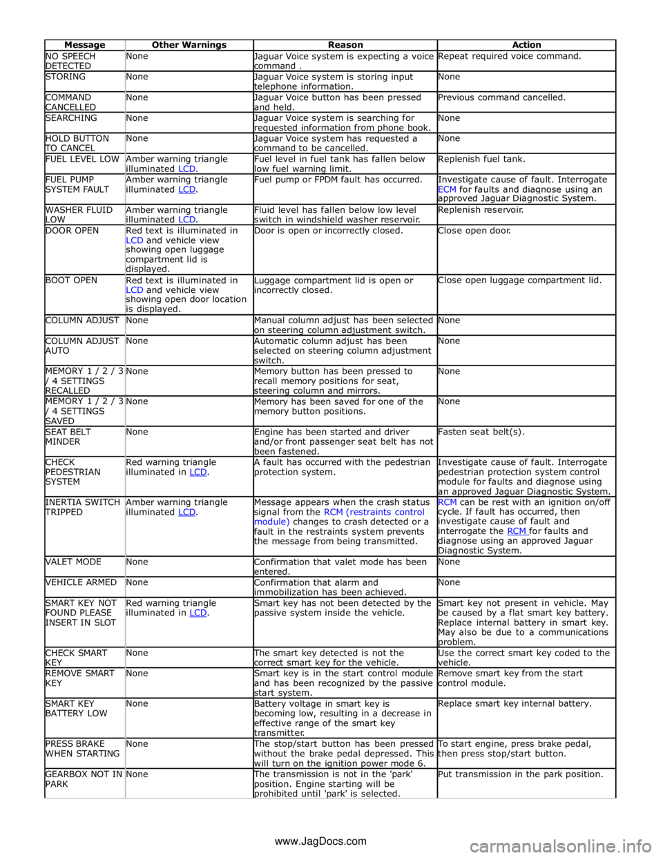
NO SPEECH
DETECTED None
Jaguar Voice system is expecting a voice
command . Repeat required voice command. STORING None
Jaguar Voice system is storing input telephone information. None COMMAND
CANCELLED None
Jaguar Voice button has been pressed
and held. Previous command cancelled. SEARCHING None
Jaguar Voice system is searching for requested information from phone book. None HOLD BUTTON TO CANCEL None
Jaguar Voice system has requested a
command to be cancelled. None FUEL LEVEL LOW
Amber warning triangle
illuminated LCD. Fuel level in fuel tank has fallen below
low fuel warning limit. Replenish fuel tank. FUEL PUMP
SYSTEM FAULT Amber warning triangle
illuminated LCD. Fuel pump or FPDM fault has occurred.
Investigate cause of fault. Interrogate
ECM for faults and diagnose using an approved Jaguar Diagnostic System. WASHER FLUID
LOW Amber warning triangle
illuminated LCD. Fluid level has fallen below low level
switch in windshield washer reservoir. Replenish reservoir. DOOR OPEN
Red text is illuminated in
LCD and vehicle view Door is open or incorrectly closed. Close open door. showing open luggage
compartment lid is
displayed. BOOT OPEN
Red text is illuminated in
LCD and vehicle view Luggage compartment lid is open or incorrectly closed. Close open luggage compartment lid. showing open door location
is displayed. COLUMN ADJUST None
Manual column adjust has been selected
on steering column adjustment switch. None COLUMN ADJUST
AUTO None
Automatic column adjust has been
selected on steering column adjustment
switch. None MEMORY 1 / 2 / 3 / 4 SETTINGS
RECALLED None
Memory button has been pressed to
recall memory positions for seat, steering column and mirrors. None MEMORY 1 / 2 / 3 / 4 SETTINGS
SAVED None
Memory has been saved for one of the
memory button positions. None SEAT BELT
MINDER None
Engine has been started and driver
and/or front passenger seat belt has not
been fastened. Fasten seat belt(s). CHECK
PEDESTRIAN
SYSTEM Red warning triangle
illuminated in LCD. A fault has occurred with the pedestrian
protection system. Investigate cause of fault. Interrogate
pedestrian protection system control
module for faults and diagnose using
an approved Jaguar Diagnostic System. INERTIA SWITCH TRIPPED Amber warning triangle
illuminated LCD. Message appears when the crash status
signal from the RCM (restraints control
module) changes to crash detected or a
fault in the restraints system prevents
the message from being transmitted. RCM can be rest with an ignition on/off cycle. If fault has occurred, then
investigate cause of fault and
interrogate the RCM for faults and diagnose using an approved Jaguar
Diagnostic System. VALET MODE None
Confirmation that valet mode has been
entered. None VEHICLE ARMED None
Confirmation that alarm and
immobilization has been achieved. None SMART KEY NOT
FOUND PLEASE
INSERT IN SLOT Red warning triangle
illuminated in LCD. Smart key has not been detected by the
passive system inside the vehicle. Smart key not present in vehicle. May
be caused by a flat smart key battery.
Replace internal battery in smart key.
May also be due to a communications problem. CHECK SMART
KEY None The smart key detected is not the
correct smart key for the vehicle. Use the correct smart key coded to the
vehicle. REMOVE SMART
KEY None
Smart key is in the start control module
and has been recognized by the passive
start system. Remove smart key from the start
control module. SMART KEY
BATTERY LOW None
Battery voltage in smart key is
becoming low, resulting in a decrease in
effective range of the smart key
transmitter. Replace smart key internal battery. PRESS BRAKE
WHEN STARTING None The stop/start button has been pressed
without the brake pedal depressed. This
will turn on the ignition power mode 6. To start engine, press brake pedal,
then press stop/start button. GEARBOX NOT IN
PARK None The transmission is not in the 'park'
position. Engine starting will be prohibited until 'park' is selected. Put transmission in the park position. www.JagDocs.com
Page 1829 of 3039
module and fuel injector operating data from the ECM.
A 'Trip' button is located on the end of the LH (left-hand) multifunction switch and allows the driver to access, in sequence, the
available trip information by repeatedly pressing the button. The trip information is displayed in the following order:
Trip distance – The trip distance since the last reset is displayed
Average speed – The average speed since the last reset is displayed
Average fuel consumption – The average fuel consumption since the last reset is displayed
Range – The range is displayed showing the distance which can be travelled until the fuel gage reads empty. If the
range display shows dashes (-), this indicates a failure with one or both of the fuel level sensors.
The trip computer has three independent memories; A, B and Auto. Memories A and B can be set independently. The Auto
memory is reset after each ignition cycle and therefore only contains information relating the current journey.
The trip information can also be accessed from the TSD located in the center console. The TSD allows the same information
available with the trip button on the multifunction switch to be displayed on the TSD, with the addition of the option to reset
the values in the A and B memories.
If the battery is disconnected, all trip data in memories A, B and Auto are erased.
Fuel Level Display
The fuel level display is a linear LCD display to show the usable fuel tank contents. The level display is active at all times when the ignition is on. Low fuel level is displayed as a LOW FUEL LEVEL message and an amber warning triangle in the
message center.
The fuel level is obtained by fuel level sensors in the fuel tank. These are monitored by the RJB software and their output resistance values, corresponding fuel quantity, are transmitted to the instrument cluster on the medium speed CAN bus. The instrument cluster uses the two level sensor signals to calculate the fuel tank contents. This calculation takes into account
fuel movement in the tank to display a steady fuel quantity in the LCD.
The fuel level information is transmitted on the medium speed and high speed CAN bus for use by other vehicle system modules.
AUDIBLE WARNINGS
The instrument cluster can generate audible warnings to alert the driver to a displayed message and change of vehicle
operating condition. The audible warning is generated by a sounder located within the instrument cluster. The audible warnings
can be generated for the warnings below and are listed in order of priority, with the first being the highest priority:
Seatbelt reminder
EPB (High Pitch)
ACC Driver Intervene 1
Airbag fault
Key in ignition switch
ASL overspeed
ACC Driver Intervene 2
EPB (Low Pitch)
Vehicle armed (entry delay)
JaguarDrive selector not in park
Valet mode
Lights on reminder
Hood operation
Passive Entry / Passive Start (PEPS)
Memory set
Turn signal indicators
Seat Belt Minder.
The audible warnings can take the form of a single chime, a number of chimes or a continuous chime. The audible warnings are
initiated by a CAN message request from the requesting sub-system control module or by the instrument cluster software.
Page 1899 of 3039
Battery
test
code,
must
be
given if
a
battery,
starter
motor
or
generator
is
exchanged
under
warranty
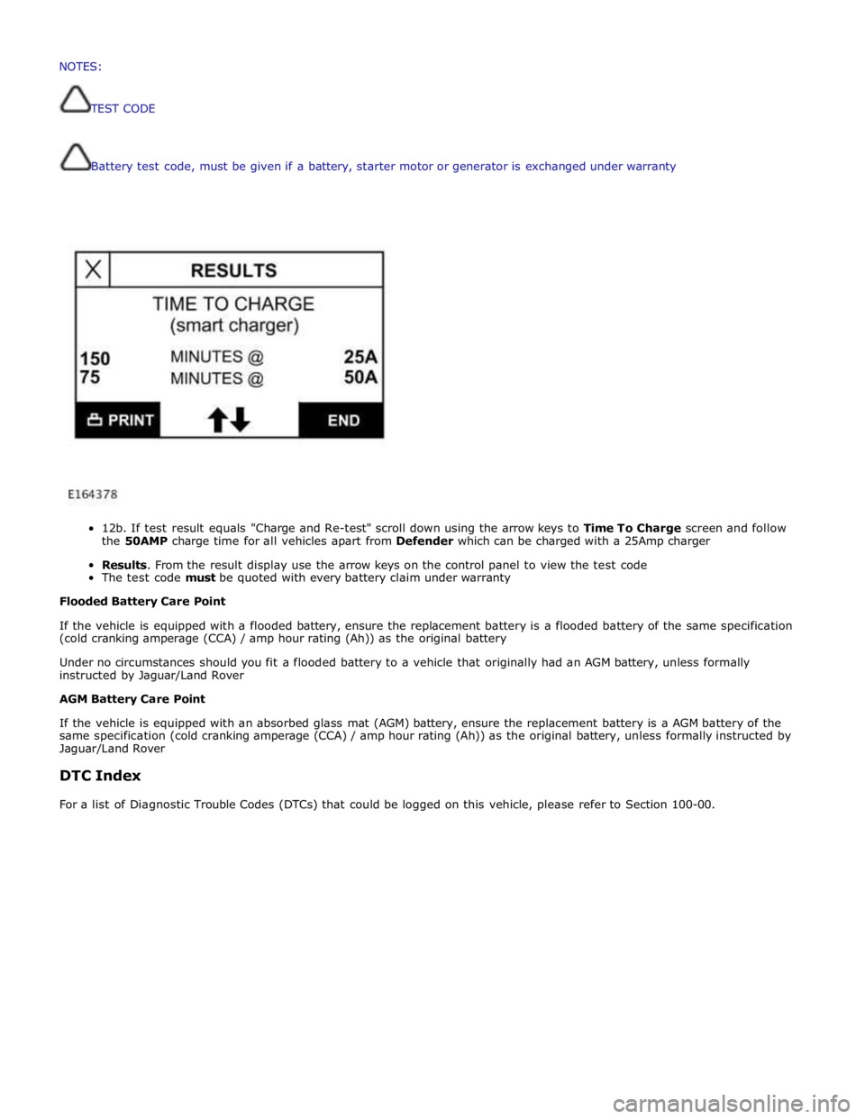
12b.
If
test
result
equals
"Charge
and
Re-test"
scroll
down
using
the
arrow
keys
to
Time To
Charge
screen and follow
the
50AMP
charge
time
for
all
vehicles
apart
from
Defender
which
can
be
charged
with a
25Amp
charger
Results.
From
the
result
display
use
the
arrow
keys
on
the
control
panel
to
view the
test
code
The
test
code
must
be
quoted
with every
battery
claim
under
warranty
Flooded
Battery
Care
Point
If
the
vehicle
is
equipped with
a
flooded
battery,
ensure
the
replacement
battery
is
a
flooded
battery
of
the
same
specification
(cold
cranking
amperage
(CCA)
/ amp
hour
rating
(Ah))
as
the
original
battery
Under
no
circumstances
should you
fit
a
flooded
battery
to a
vehicle
that
originally
had
an
AGM
battery,
unless
formally
instructed
by Jaguar/Land
Rover
AGM
Battery
Care
Point
If
the
vehicle
is
equipped with
an absorbed
glass
mat
(AGM)
battery,
ensure
the
replacement
battery
is
a
AGM
battery
of
the
same
specification
(cold
cranking
amperage
(CCA)
/
amp
hour
rating
(Ah))
as
the
original
battery,
unless
formally
instructed
by
Jaguar/Land
Rover
DTC
Index
For
a
list
of
Diagnostic
Trouble
Codes
(DTCs)
that
could
be
logged
on
this
vehicle,
please
refer
to
Section
100-00. NOTES:
TESTCODE
Page 2058 of 3039
3 BJB - Megafuse 4 RJB 5 Glovebox lamp 6 Glovebox lamp switch 7 LH footwell lamp 8 RH footwell lamp 9 LH vanity mirror 10 RH vanity mirror 11 LH rear interior lamp 12 RH rear interior lamp 13 CJB 14 Ambience lighting LED's 15 LH map reading lamp 16 Courtesy lamp 17 RH map reading lamp
JUNCTION BOXES
Inputs System Operation
The CJB receives the following inputs which affect the operation of the interior lamps: Ignition mode
Lock/unlock
Luggage compartment lid latch switch
Door latch switches.
Outputs
The RJB outputs the following for the interior lighting system: Luggage compartment lamp power supply
Driver and passenger door module power supplies
Fade on and off grounds for front and rear overhead console interior lamps and footwell lamps
PWM (pulse width modulation) power output for the ambience lighting.
Interior Lamp Time-Out
The interior lamps are controlled by a timer within the CJB which allows a 60 second delay period for the lamps to remain active after the ignition mode has been changed to off power mode 0 or the vehicle has been unlocked. The interior lamp fade
off is controlled by the RJBvia a delayed power off relay in the CJB. The following interior lamps are subject to the delay period:
Front overhead console interior lamp
Rear interior lamps
Footwell lamps
Door mirror approach lamps.
The timer delay is activated when the CJB receives one of the following signals: An unlock signal from the Smart Key via the keyless vehicle module.
Ignition mode is changed from the crank power mode 9 or ignition power mode 6 to the accessory power mode 4 to the
off power mode 0.
If a second occurrence of the above actions occurs within the timer period, the timer will be rest and the delay period timer will
restart.
The timer delay is deactivated when the CJB receives one of the following signals: A lock signal from the Smart Key via the keyless vehicle module
Ignition mode is changed from the off power mode 0 to the accessory power mode 4 or ignition power mode 6
The CJB receives a door opened signal (even if that door is subsequently closed). Battery Saver
The battery saver provides an automatic shut-off of the interior lamps after a period of 15 minutes in order to prevent
excessive power drain on the battery.
When the ignition mode is changed from the ignition power mode 6 or accessory power mode 4 to the off power mode 0, the
CJB starts a timer which de-energizes a delayed power off relay in the CJB, removing the power supply to the interior lamps after a period of 15 minutes, switching off all or any interior lamps which have remained on for any reason.
Page 2059 of 3039
Once the timer has expired and the lamps are off, any one of the following will 'wake up' the battery saver and the interior
lamps will function again. The timer will be restarted as soon as an input is received by the CJB from one of the following:
Ignition mode changed from off power mode 0 to accessory power mode 4, ignition power mode 6 or crank power mode
9.
Any door, including the luggage compartment lid is opened
An unlock request is received from the Smart Key via the keyless vehicle module
Overhead console interior lamp is switched on via the JaguarSense function.
INTERIOR LAMPS
When the interior lighting system switches the interior lamps on, the CJB ramps the lamps up to full power over a period of 1.3 seconds. When the system switches the lamps off, after the time-out period has expired, the CJB fades the lamps off over a period of 2.6 seconds.
The interior lighting system will illuminate the interior lamps when one of the following events occurs:
The CJB receives an unlock signal from the Smart Key via the keyless vehicle module Any door is opened including the luggage compartment lid
The ignition mode is changed from ignition power mode 6 or accessory power mode 4 to off power mode 0.
The interior lighting system will turn off the interior lamps when one of the following events occurs:
Once the time-out timer delay has expired since the lamps were either activated or the last door is closed and the
vehicle is not locked
The ignition is in off power mode 0 and an external lock is requested (using either the door lock buttons or the Smart
Key) with all doors closed
The ignition mode is changed from the off power mode 0 or the accessory power mode 4 to the ignition power mode 6
The last door is closed and the vehicle is externally locked, on receipt of an unlock request from the Smart Key or door
handle operation detected when the time-out timer is still active.
DELIVERY MODE
Delivery mode is set at the factory on vehicles to minimize battery drain. The mode enables the switching off of non-critical
electrical components, including the interior lighting system. The delivery mode feature is cancelled by the dealer during the
Pre-Delivery Inspection using an approved Jaguar diagnostic system.
CRASH ILLUMINATION
When a crash signal is received from the RCM (restraints control module), the CJB activates the interior lamps once the vehicle speed has reduced to 5 km/h (3.1 mph). The hazard flashers are also activated and the doors are prevented from being locked.
The lamps remain on until the crash signal is removed, they cannot be switched off using the JaguarSense feature. The crash
signal is removed by completing one ignition on and off cycle.
INTERIOR BULB TYPE/RATING Component Description
The following table shows the bulbs used for the interior lighting system and their type and specification.
NOTE: The front overhead console and the front door ambience lighting is illuminated by LED's and are non-serviceable components.
Bulb Type Rating Front overhead console - interior lamp W6WX 6W Front overhead console - LH/RH map reading lamps W6WX 6W Rear interior lamps W6WX 10W Sunvisor lamps TS1.3W 1.3W LH/RH footwell lamps W5W 5W Glovebox lamp W5W 5W LH/RH door mirror approach lamps W5W 5W Luggage compartment lamp S10W 10W JUNCTION BOXES
The CJB is an integrated unit located on the RH 'A' pillar, below the instrument panel. The CJB contains fuses, relays and number of microprocessors which control the power supply and functionality of the interior lighting system and other vehicle
systems.
The RJB is located on the RH side of the luggage compartment. The RJB contains fuses, relays and microprocessors which in conjunction with the CJB control the interior lighting system and other vehicle systems. Circuit Protection
The CJB and the RJB provide circuit protection for all interior lamp circuits. The lamps are protected by fuses in the CJB and the RJB.
Page 2124 of 3039
The battery backed sounder is disconnected (partial trigger only).
The vehicle battery is disconnected on a vehicle fitted with a battery backed sounder (partial trigger only).
The inclination sensor detects a change in vehicle attitude.
The intrusion detection module detects movement within the cabin.
Door Modules Component Description
The door modules provide the interface between the door latch-motors, the door latch-switches and the CJB. The door modules
provide door switch status information and enable the door latch-motors on request from the CJB or the keyless vehicle
module.
Keyless Vehicle Module
The keyless vehicle module interfaces with the Central locking, Radio Frequency (RF) receiver and collects RF signal information
which is transmitted from the Smart Key. This information is translated into commands which are passed on the medium speed
CAN bus to the:
CJB,
RJB,
door modules, and
instrument cluster.
The keyless vehicle module also monitors:
2 interior antennae,
1 luggage compartment antenna,
a rear bumper antenna, and
4 door handle antennae if the passive entry system is fitted.
On vehicles with passive entry, the additional fast latch motors are controlled via the keyless vehicle module and the locking
status is passed to the CJB on the medium speed CAN bus.
Instrument Cluster
The instrument cluster controls the alarm indicator, and in conjunction with the ECM (engine control module), the engine
immobilization. The ECM controls the engine crank and fuel functions and the instrument cluster processes the valid
transponder information.
Alarm Indicator
The alarm indicator is a LED (light emitting diode) located in the body of the sunload/light sensor. When the ignition is off the
indicator gives a visual indication of the active anti-theft system to show if the alarm system is active or not active. Operation
of the alarm indicator is controlled by the instrument cluster which varies the flash rate of the LED to indicate the system
status of the alarm and the immobilization systems.
When the ignition is on, the indicator provides a visual indication of the status of the passive anti-theft (engine
immobilization) system. If the immobilization system is operating correctly, the LED will be illuminated for 3 seconds at
ignition on and then extinguish. If a fault exists in the immobilization system, the LED will be either permanently illuminated
or flashing for 60 seconds. This indicates that a fault exists and fault code has been recorded. After the 60 second period the
LED will flash at different frequencies which indicate the nature of the fault.
Refer to: Anti-Theft - Passive (419-01B Anti-Theft - Passive, Description and Operation).
Passive Anti-Theft Horn
The passive anti-theft horn is hardwired to the CJB which activates the horn when the alarm is triggered.
Battery Backed Sounder
Operation of the battery backed sounder is controlled by the CJB on the LIN bus. The sounder is also connected with a
permanent battery supply via the CJB. An integral, rechargeable battery powers the sounder if the battery power supply from
the CJB is interrupted.
Dependant on vehicle, a incitation sensor is incorporated into the battery backed sounder, to monitor vehicle attitude, see
Inclination Sensor.
Inclination Sensor
The CJB monitors the inclination sensor and will activate the alarm system if the vehicle is being raised.
Intrusion Detection Module
The intrusion detection module comprises an ultrasonic sound wave sensor which monitors the vehicle's interior.
The intrusion detection module is activated with volumetric mode which in turn is enabled when the vehicle is double locked.
The vehicle can be locked and alarmed with the module de-activated if a pet is to be left in the vehicle for example by single-
Page 2143 of 3039
7 Low frequency antenna - front 8 Low frequency antenna - center 9 Low frequency antenna - rear 10 Radio frequency receiver 11 Start control module 12 CJB (central junction box) 13 Instrument cluster 14 Megafuse (250 amp)
System Operation
The passive start function prevents the vehicle from being started by unauthorized persons. It does this by immobilizing the
ignition, fuel and engine crank functions. The system is automatic and requires no input from the driver.
At the request of the CJB, the keyless vehicle module prompts each of the Low Frequency (LF) antennae to output a signal. When the Smart Key is in the vehicle cabin, it detects the LF signals and responds with a Radio Frequency (RF)
data-identification signal back to the keyless vehicle module via the RF receiver.
If the data received matches that stored in the keyless vehicle module it continues the passive start process by
communicating a 'Smart Key valid’ signal to the CJB via the medium speed CAN (controller area network) bus.
Once the CJB receives the authorization and confirms a response with an internal calculation, it passes the result to the
instrument cluster on the medium speed CAN bus.
Before the instrument cluster sends a mobilization signal to the ECMit will exchange encrypted data with: The electric steering lock mechanism to authorize unlocking the steering column.
The RJB to authorize fuel pump operation. Once the RJB receives the authorization and confirms the response with an internal calculation, it will enable the FPDM (fuel pump driver module).
The CJB to authorize the ignition status. If the drive selector is in the park position and the driver presses the brake
pedal and simultaneously presses the start/stop switch, the CJB interprets this as an engine crank request. Before the
engine crank request is allowed, the CJB compares a brake pressure signal received from the ABS module. The brake pressure signal is compared to an internally stored threshold value within the CJB. If the signal is greater than the
stored threshold value, a crank request signal is sent to the ECM on the high speed CAN bus.
Once these factors have been confirmed, and the vehicle is in 'Park', the engine can be started by pressing the brake pedal and
the Stop/Start button simultaneously.
NOTES:
If the keyless vehicle module fails to locate the Smart Key, the message 'SMART KEY NOT FOUND PLEASE INSERT IN
SLOT' will appear in the instrument cluster message center. When inserted the start control module will read the transponder
within the Smart Key. If the transponder identification is valid, authorization will be transmitted to the instrument cluster on
the LIN (local interconnect network) bus.
When the vehicle is delivered from the factory the passive start function is inhibited. In this condition the vehicle can
only be started by placing the Smart Key in the start control module. The system should be switched on during the Pre-Delivery
Inspection (PDI) using the Jaguar approved diagnostic system. For additional information, refer to the PDI Manual.
To ensure optimum long term reliability of the smart key the battery must be replaced with a brand new, unused battery. If a
used battery is installed the "SMART KEY BATTERY LOW" message may not be cleared. To avoid contamination of the contacts
the battery should be removed from its packaging and installed into the smart key while wearing gloves. To confirm that the
replacement battery is working correctly press the unlock button twice while holding the smart key outside the vehicle, then
enter the vehicle with the smart key, press the start button and confirm that the "SMART KEY BATTERY LOW" message is not
displayed.
Start Control Module Component Description
The start control module is used if the keyless vehicle module is unable to authorise the Smart Key.
If the keyless vehicle module is unable to identify the Smart Key, for example if the Smart Key battery voltage is low or there
is local RF interference, the transponder within the Smart Key can be read in the conventional manner. The driver will be
alerted to this by a chime and a message in the instrument cluster message center 'SMART KEY NOT FOUND PLEASE INSERT IN
SLOT'.
Once inserted the start control module will read the transponder within the Smart Key. If the transponder identification is
valid, authorization will be transmitted to the instrument cluster on the LIN bus.
NOTE: Inserting the Smart Key into the start control module will not charge the Smart Key battery. The battery is
non-chargeable and must be replaced if defective.