fuel tank removal JAGUAR XFR 2010 1.G Workshop Manual
[x] Cancel search | Manufacturer: JAGUAR, Model Year: 2010, Model line: XFR, Model: JAGUAR XFR 2010 1.GPages: 3039, PDF Size: 58.49 MB
Page 12 of 3039
SpecificationDescription and OperationComponent Location
Overview
System Operation and Component DescriptionDiagnosis and TestingEngine Cooling - V8 5.0L Petrol/V8 S/C 5.0L PetrolGeneral ProceduresCooling System Draining and Vacuum Filling
Cooling System Partial Draining, Filling and Bleeding - V8 S/C 5.0L Petrol
Cooling System Draining, Filling and Bleeding - V8 S/C 5.0L PetrolRemoval and InstallationAuxiliary Radiator
Coolant Expansion Tank
Cooling Fan Motor and Shroud - Vehicles With: Supercharger
Cooling Module - Vehicles With: Supercharger
Coolant Pump - Vehicles With: Supercharger
Radiator (26.40.01) - Vehicles With: Supercharger
Thermostat Housing - Vehicles With: Supercharger303-03D: Supercharger Cooling - V8 S/C 5.0L Petrol
Description and OperationComponent Location
Overview
System Operation and Component DescriptionRemoval and InstallationRadiator303-04E: Fuel Charging and Controls - V8 S/C 5.0L PetrolSpecificationDescription and OperationComponent Location
Overview
System Operation and Component DescriptionDiagnosis and TestingFuel Charging and ControlsGeneral ProceduresFuel Injection Component CleaningRemoval and InstallationFuel Injectors
Fuel Rail LH
Fuel Rail RH
Left-Hand Fuel Rail High-Pressure Fuel Pump
Right-Hand Fuel Rail High-Pressure Fuel Pump303-03C: Engine Cooling - V8 5.0L Petrol/V8 S/C 5.0L Petrol
Page 17 of 3039
310: Fuel System - General Information
310-00: Fuel System - General InformationSpecificationGeneral ProceduresFuel System Pressure Release - V8 5.0L Petrol/V8 S/C 5.0L Petrol
Fuel Tank Draining
Spring Lock Couplings
Quick Release Coupling
Quick Release Coupling - Push Connect310-01C: Fuel Tank and Lines - V8 5.0L Petrol/V8 S/C 5.0L PetrolSpecificationDescription and OperationComponent Location
Overview
System Operation and Component DescriptionDiagnosis and TestingFuel Tank and LinesRemoval and InstallationFuel Level Sender
Fuel Pump and Sender Unit
Fuel Tank
Fuel Tank Filler Pipe
Fuel Rail High-Pressure Fuel Pump Supply Line310-02: Acceleration ControlSpecificationDiagnosis and TestingAcceleration ControlRemoval and InstallationAccelerator Pedal310-03C: Speed Control - V8 5.0L Petrol/V8 S/C 5.0L PetrolSpecificationDescription and OperationComponent Location
Overview
System Operation and Component DescriptionDiagnosis and TestingSpeed ControlGeneral ProceduresSpeed Control Sensor AdjustmentRemoval and InstallationSpeed Control Deactivator Switch
Page 412 of 3039
Rear Suspension - Rear Stabilizer Bar
Removal and Installation Published: 06-Jun-2013
Removal
1. Disconnect the battery ground cable.
For additional information, refer to: Battery Disconnect and Connect (414-01 Battery, Mounting and Cables, General Procedures).
2. WARNING: Make sure to support the vehicle with axle stands.
Raise and support the vehicle.
3. Remove both rear wheels and tires.
For additional information, refer to: Wheel and Tire (204-04 Wheels and Tires, Removal and Installation).
4. Drain the fuel tank.
For additional information, refer to: Fuel Tank Draining (310-00 Fuel System - General Information, General Procedures).
5. Remove the exhaust system.
For additional information, refer to: Front Muffler (309-00B Exhaust System - V6 3.0L Petrol, Removal and Installation).
6. CAUTION: Always plug any open connections to
prevent contamination.
NOTES:
To prevent the loss of brake fluid, using the special
tool apply the brake pedal and set to 40mm ( 1.6 in ) below
the rest position.
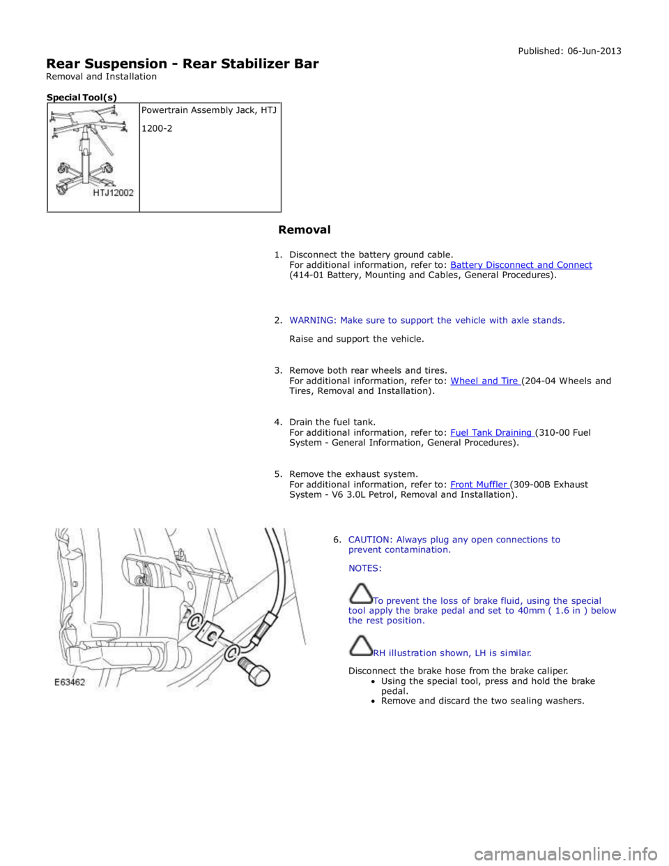
RH illustration shown, LH is similar.
Disconnect the brake hose from the brake caliper.
Using the special tool, press and hold the brake
pedal.
Remove and discard the two sealing washers. Powertrain Assembly Jack, HTJ
1200-2 Special Tool(s)
Page 421 of 3039
System - V6 3.0L Petrol, Removal and Installation).
19. Refill the fuel tank.
For additional information, refer to: Fuel Tank Draining (310-00 Fuel System - General Information, General Procedures).
20. Bleed the brake system.
For additional information, refer to: Brake System Bleeding (206-00 Brake System - General Information, General Procedures).
21. Install the rear wheels and tires.
For additional information, refer to: Wheel and Tire (204-04 Wheels and Tires, Removal and Installation).
22. Connect the battery ground cable.
For additional information, refer to: Battery Disconnect and Connect (414-01 Battery, Mounting and Cables, General Procedures).
23. Using only four-wheel alignment equipment approved by Jaguar, check
and adjust the wheel alignment.
For additional information, refer to: Camber and Caster Adjustment (204-00 Suspension System - General Information, General Procedures).
Page 1566 of 3039
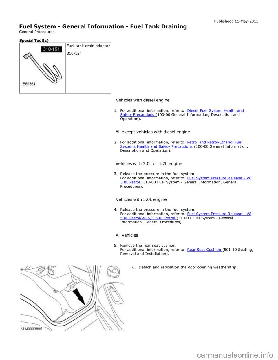
Safety Precautions (100-00 General Information, Description and Operation).
All except vehicles with diesel engine
2. For additional information, refer to: Petrol and Petrol-Ethanol Fuel Systems Health and Safety Precautions (100-00 General Information, Description and Operation).
Vehicles with 3.0L or 4.2L engine
3. Release the pressure in the fuel system.
For additional information, refer to: Fuel System Pressure Release - V6 3.0L Petrol (310-00 Fuel System - General Information, General Procedures).
Vehicles with 5.0L engine
4. Release the pressure in the fuel system.
For additional information, refer to: Fuel System Pressure Release - V8 5.0L Petrol/V8 S/C 5.0L Petrol (310-00 Fuel System - General Information, General Procedures).
All vehicles
5. Remove the rear seat cushion.
For additional information, refer to: Rear Seat Cushion (501-10 Seating, Removal and Installation).
6. Detach and reposition the door opening weatherstrip. Fuel tank drain adaptor
310-154 Special Tool(s)
Page 1599 of 3039
Published: 11-May-2011
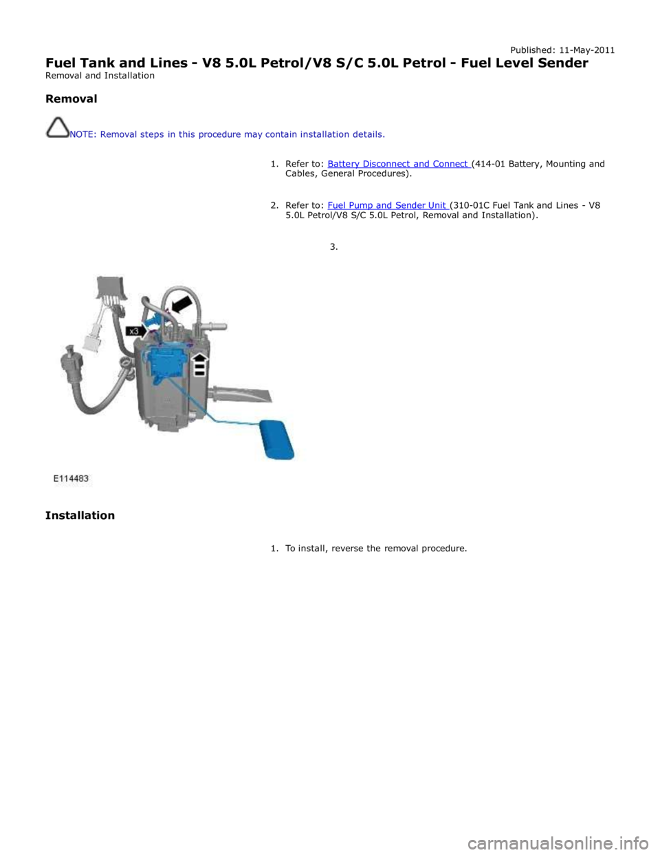
Fuel Tank and Lines - V8 5.0L Petrol/V8 S/C 5.0L Petrol - Fuel Level Sender
Removal and Installation
Removal
NOTE: Removal steps in this procedure may contain installation details.
1. Refer to: Battery Disconnect and Connect (414-01 Battery, Mounting and Cables, General Procedures).
2. Refer to: Fuel Pump and Sender Unit (310-01C Fuel Tank and Lines - V8 5.0L Petrol/V8 S/C 5.0L Petrol, Removal and Installation).
3.
Installation
1. To install, reverse the removal procedure.
Page 1600 of 3039
Published: 09-Dec-2012
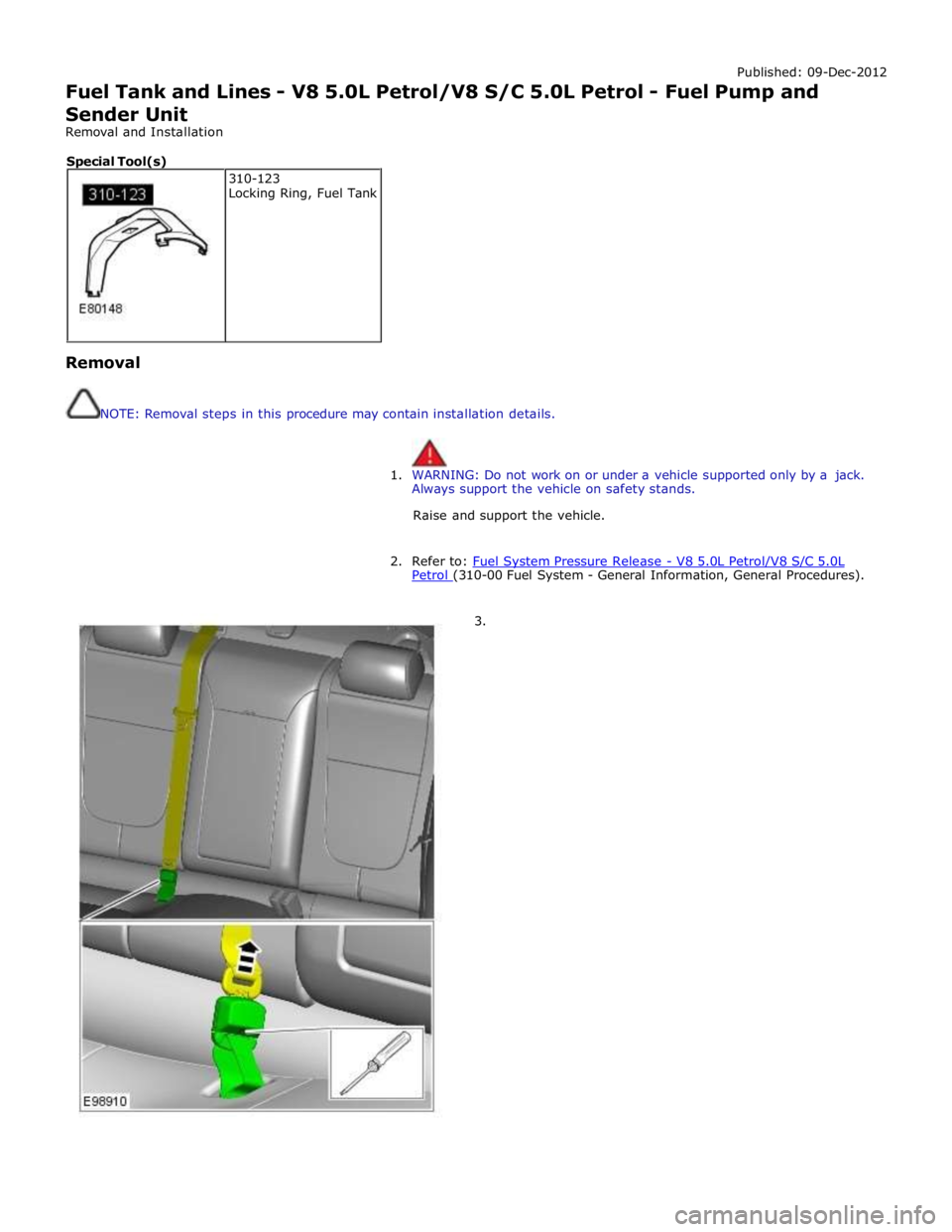
Fuel Tank and Lines - V8 5.0L Petrol/V8 S/C 5.0L Petrol - Fuel Pump and
Sender Unit
Removal and Installation
Removal
NOTE: Removal steps in this procedure may contain installation details.
1. WARNING: Do not work on or under a vehicle supported only by a jack.
Always support the vehicle on safety stands.
Raise and support the vehicle.
2. Refer to: Fuel System Pressure Release - V8 5.0L Petrol/V8 S/C 5.0L Petrol (310-00 Fuel System - General Information, General Procedures).
3. 310-123
Locking Ring, Fuel Tank Special Tool(s)
Page 1604 of 3039
Installation
1. CAUTIONS:
arm. Take extra care not to damage the fuel tank level sensor float and
Make sure the fuel pump and sender unit is correctly installed in to
the retaining bracket in the fuel tank.
NOTE: Make sure the locating tang is installed in the correct
position.
To install, reverse the removal procedure.
Page 1605 of 3039
Published: 11-May-2011
Fuel Tank and Lines - V8 5.0L Petrol/V8 S/C 5.0L Petrol - Fuel Tank
Removal and Installation
Removal
NOTE: Removal steps in this procedure may contain installation details.
1. Refer to: Petrol and Petrol-Ethanol Fuel Systems Health and Safety Precautions (100-00 General Information, Description and Operation).
2. Refer to: Battery Disconnect and Connect (414-01 Battery, Mounting and Cables, General Procedures).
3. Refer to: Fuel Tank Draining (310-00 Fuel System - General Information, General Procedures).
4. WARNING: Do not work on or under a vehicle supported only by a jack.
Always support the vehicle on safety stands.
Raise and support the vehicle.
5. Refer to: Driveshaft - V8 5.0L Petrol/V8 S/C 5.0L Petrol (205-01 Driveshaft, Removal and Installation).
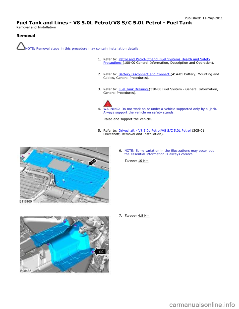
6. NOTE: Some variation in the illustrations may occur, but
the essential information is always correct.
Torque: 10 Nm
7. Torque: 4.8 Nm
Page 1609 of 3039
Published: 18-Jun-2014
Fuel Tank and Lines - V8 5.0L Petrol/V8 S/C 5.0L Petrol - Fuel Tank Filler
Pipe
Removal and Installation
Removal
NOTE: Removal steps in this procedure may contain installation details.
1. Refer to: Diesel Fuel System Health and Safety Precautions (100-00 General Information, Description and Operation).
Refer to: Petrol and Petrol-Ethanol Fuel Systems Health and Safety Precautions (100-00 General Information, Description and Operation).
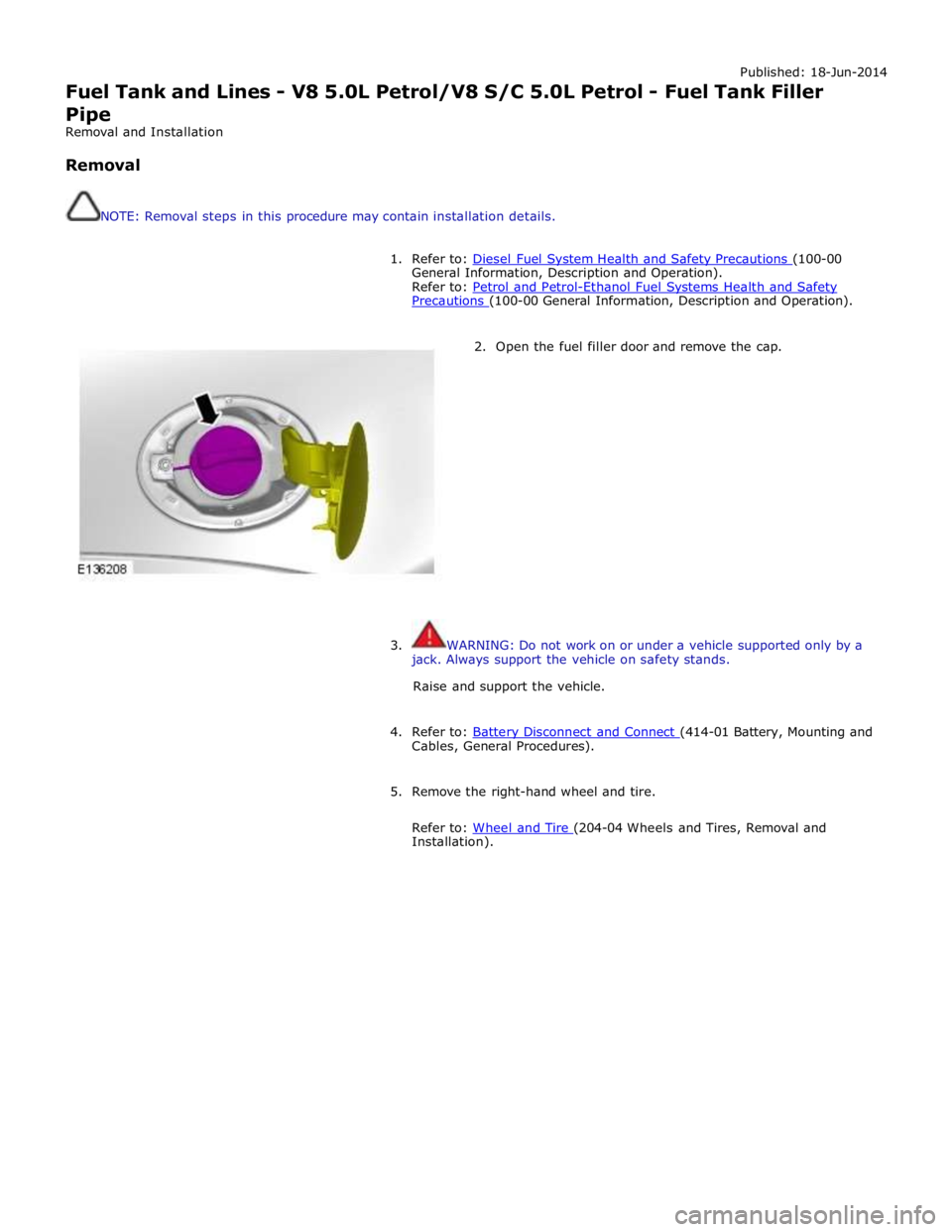
2. Open the fuel filler door and remove the cap.
3. WARNING: Do not work on or under a vehicle supported only by a
jack. Always support the vehicle on safety stands.
Raise and support the vehicle.
4. Refer to: Battery Disconnect and Connect (414-01 Battery, Mounting and Cables, General Procedures).
5. Remove the right-hand wheel and tire.
Refer to: Wheel and Tire (204-04 Wheels and Tires, Removal and Installation).