radiator JAGUAR XFR 2010 1.G Workshop Manual
[x] Cancel search | Manufacturer: JAGUAR, Model Year: 2010, Model line: XFR, Model: JAGUAR XFR 2010 1.GPages: 3039, PDF Size: 58.49 MB
Page 12 of 3039

SpecificationDescription and OperationComponent Location
Overview
System Operation and Component DescriptionDiagnosis and TestingEngine Cooling - V8 5.0L Petrol/V8 S/C 5.0L PetrolGeneral ProceduresCooling System Draining and Vacuum Filling
Cooling System Partial Draining, Filling and Bleeding - V8 S/C 5.0L Petrol
Cooling System Draining, Filling and Bleeding - V8 S/C 5.0L PetrolRemoval and InstallationAuxiliary Radiator
Coolant Expansion Tank
Cooling Fan Motor and Shroud - Vehicles With: Supercharger
Cooling Module - Vehicles With: Supercharger
Coolant Pump - Vehicles With: Supercharger
Radiator (26.40.01) - Vehicles With: Supercharger
Thermostat Housing - Vehicles With: Supercharger303-03D: Supercharger Cooling - V8 S/C 5.0L Petrol
Description and OperationComponent Location
Overview
System Operation and Component DescriptionRemoval and InstallationRadiator303-04E: Fuel Charging and Controls - V8 S/C 5.0L PetrolSpecificationDescription and OperationComponent Location
Overview
System Operation and Component DescriptionDiagnosis and TestingFuel Charging and ControlsGeneral ProceduresFuel Injection Component CleaningRemoval and InstallationFuel Injectors
Fuel Rail LH
Fuel Rail RH
Left-Hand Fuel Rail High-Pressure Fuel Pump
Right-Hand Fuel Rail High-Pressure Fuel Pump303-03C: Engine Cooling - V8 5.0L Petrol/V8 S/C 5.0L Petrol
Page 25 of 3039

SpecificationRemoval and InstallationAir Deflector
Cowl Vent Screen (76.10.01)
Engine Rear Undershield
Fender Splash Shield
Hood
Radiator Splash Shield
Secondary Bulkhead Center Panel
Secondary Bulkhead Panel LH - TDV6 3.0L Diesel /V8 5.0L Petrol/V8 S/C 5.0L Petrol
Secondary Bulkhead Panel RH - TDV6 3.0L Diesel /V8 5.0L Petrol/V8 S/C 5.0L Petrol501-03: Body Closures
Removal and InstallationFront Door
Fuel Filler Door
Fuel Filler Door Assembly
Luggage Compartment Lid (76.19.01)
Rear Door501-05: Interior Trim and OrnamentationSpecificationRemoval and InstallationA-Pillar Trim Panel
B-Pillar Lower Trim Panel
B-Pillar Upper Trim Panel
C-Pillar Lower Trim Panel
C-Pillar Trim Panel
Cowl Side Trim Panel
Engine Cover - V8 5.0L Petrol/V8 S/C 5.0L Petrol
Front Door Trim Panel (76.34.01)
Front Scuff Plate Trim Panel
Instrument Panel Speaker Grille
Headliner
Loadspace Scuff Plate Trim Panel
Loadspace Trim Panel
Loadspace Trim Panel LH
Loadspace Trim Panel RH
Luggage Compartment Lid Trim Panel
Parcel Shelf
Rear Door Trim Panel
Rear Scuff Plate Trim Panel
Sun Visor (76.10.48)
Sun Visor Vanity Mirror
Page 26 of 3039

SpecificationRemoval and InstallationRadiator Grille
Luggage Compartment Lid Moulding
Front Fender Moulding
Rocker Panel Moulding501-09: Rear View MirrorsSpecificationDescription and OperationComponent Location
Overview
System Operation and Component DescriptionDiagnosis and TestingRear View MirrorsRemoval and InstallationExterior Mirror
Exterior Mirror Cover
Exterior Mirror Glass
Exterior Mirror Motor
Interior Rear View Mirror501-10: SeatingSpecificationDescription and OperationComponent Location
Overview
System Operation and Component Description
Seat Cover InspectionDiagnosis and TestingSeats
Heater Mats
Seats - Vehicles With: Climate Controlled SeatsGeneral ProceduresSeat SmoothingRemoval and InstallationFront Seat (76.70.01)
Front Seat Backrest (76.70.06)
Front Seat Backrest Cover (76.70.15)
Front Seat Bolster
Front Seat Bolster Pump
Front Seat Cushion Cover
Front Seat Track Motor
Lumbar Assembly501-08: Exterior Trim and Ornamentation
Page 303 of 3039
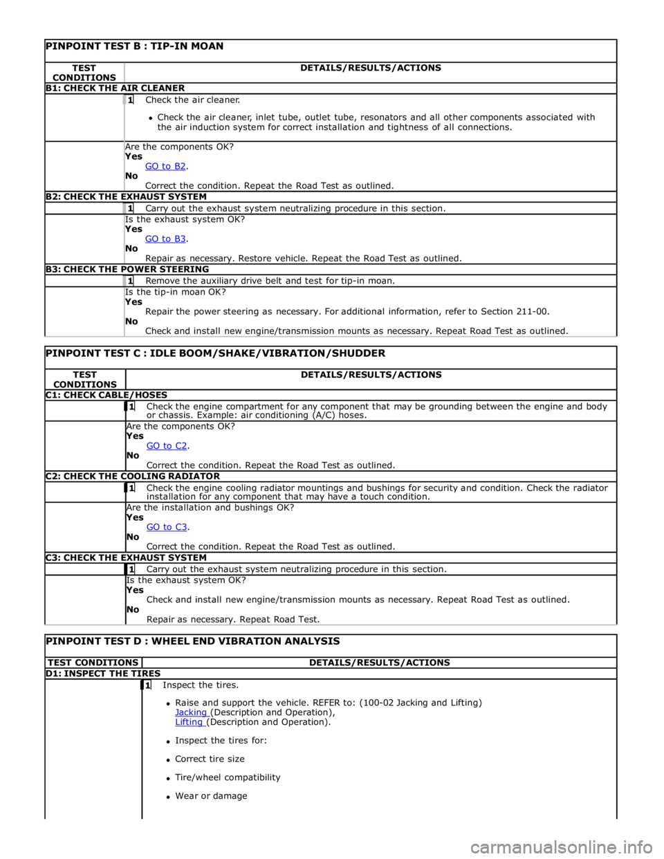
PINPOINT TEST B : TIP-IN MOAN TEST
CONDITIONS DETAILS/RESULTS/ACTIONS B1: CHECK THE AIR CLEANER 1 Check the air cleaner.
Check the air cleaner, inlet tube, outlet tube, resonators and all other components associated with
the air induction system for correct installation and tightness of all connections. Are the components OK? Yes
GO to B2. No
Correct the condition. Repeat the Road Test as outlined. B2: CHECK THE EXHAUST SYSTEM 1 Carry out the exhaust system neutralizing procedure in this section. Is the exhaust system OK? Yes
GO to B3. No
Repair as necessary. Restore vehicle. Repeat the Road Test as outlined. B3: CHECK THE POWER STEERING 1 Remove the auxiliary drive belt and test for tip-in moan. Is the tip-in moan OK? Yes
Repair the power steering as necessary. For additional information, refer to Section 211-00.
No
Check and install new engine/transmission mounts as necessary. Repeat Road Test as outlined.
PINPOINT TEST C : IDLE BOOM/SHAKE/VIBRATION/SHUDDER TEST
CONDITIONS DETAILS/RESULTS/ACTIONS C1: CHECK CABLE/HOSES 1 Check the engine compartment for any component that may be grounding between the engine and body or chassis. Example: air conditioning (A/C) hoses. Are the components OK? Yes
GO to C2. No
Correct the condition. Repeat the Road Test as outlined. C2: CHECK THE COOLING RADIATOR 1 Check the engine cooling radiator mountings and bushings for security and condition. Check the radiator installation for any component that may have a touch condition. Are the installation and bushings OK? Yes
GO to C3. No
Correct the condition. Repeat the Road Test as outlined. C3: CHECK THE EXHAUST SYSTEM 1 Carry out the exhaust system neutralizing procedure in this section. Is the exhaust system OK? Yes
Check and install new engine/transmission mounts as necessary. Repeat Road Test as outlined.
No
Repair as necessary. Repeat Road Test.
PINPOINT TEST D : WHEEL END VIBRATION ANALYSIS TEST CONDITIONS DETAILS/RESULTS/ACTIONS D1: INSPECT THE TIRES 1 Inspect the tires.
Raise and support the vehicle. REFER to: (100-02 Jacking and Lifting)
Jacking (Description and Operation), Lifting (Description and Operation).
Inspect the tires for:
Correct tire size
Tire/wheel compatibility
Wear or damage
Page 356 of 3039
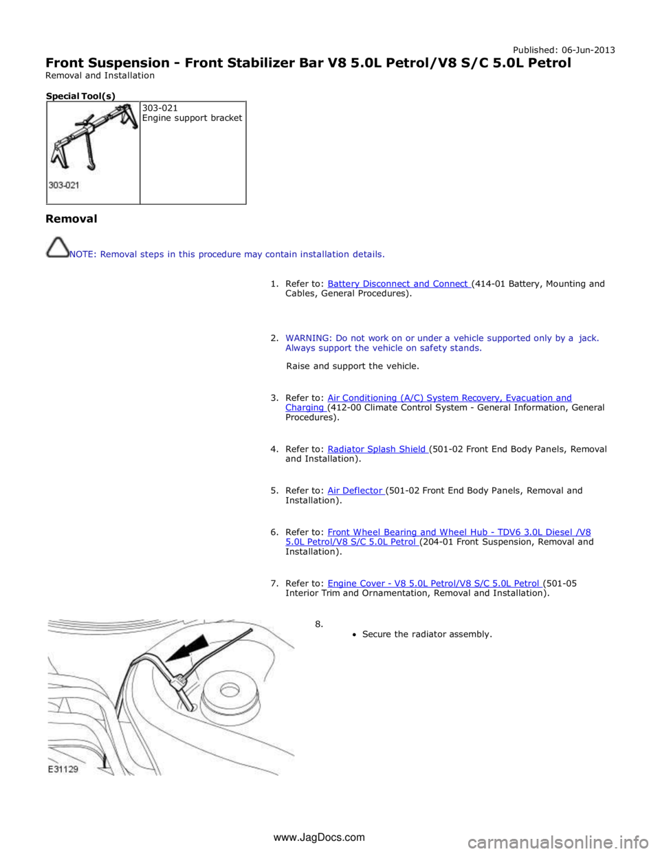
Published: 06-Jun-2013
Front Suspension - Front Stabilizer Bar V8 5.0L Petrol/V8 S/C 5.0L Petrol
Removal and Installation
Removal
NOTE: Removal steps in this procedure may contain installation details.
1. Refer to: Battery Disconnect and Connect (414-01 Battery, Mounting and Cables, General Procedures).
2. WARNING: Do not work on or under a vehicle supported only by a jack.
Always support the vehicle on safety stands.
Raise and support the vehicle.
3. Refer to: Air Conditioning (A/C) System Recovery, Evacuation and Charging (412-00 Climate Control System - General Information, General Procedures).
4. Refer to: Radiator Splash Shield (501-02 Front End Body Panels, Removal and Installation).
5. Refer to: Air Deflector (501-02 Front End Body Panels, Removal and Installation).
6. Refer to: Front Wheel Bearing and Wheel Hub - TDV6 3.0L Diesel /V8 5.0L Petrol/V8 S/C 5.0L Petrol (204-01 Front Suspension, Removal and Installation).
7. Refer to: Engine Cover - V8 5.0L Petrol/V8 S/C 5.0L Petrol (501-05 Interior Trim and Ornamentation, Removal and Installation).
8.
Secure the radiator assembly. 303-021
Engine support bracket Special Tool(s) www.JagDocs.com
Page 471 of 3039
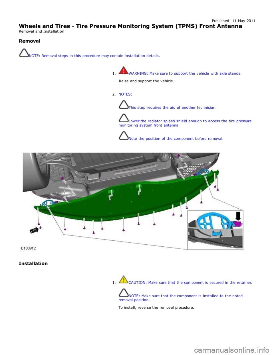
Published: 11-May-2011
Wheels and Tires - Tire Pressure Monitoring System (TPMS) Front Antenna
Removal and Installation
Removal
NOTE: Removal steps in this procedure may contain installation details.
1. WARNING: Make sure to support the vehicle with axle stands.
Raise and support the vehicle.
2. NOTES:
This step requires the aid of another technician.
Lower the radiator splash shield enough to access the tire pressure
monitoring system front antenna.
Note the position of the component before removal.
Installation
1. CAUTION: Make sure that the component is secured in the retainer.
NOTE: Make sure that the component is installed to the noted
removal position.
To install, reverse the removal procedure.
Page 486 of 3039
2 Main piston 3 Tube 4 Bypass valve (closed) 5 Piston and rod assembly ACCELEROMETERS
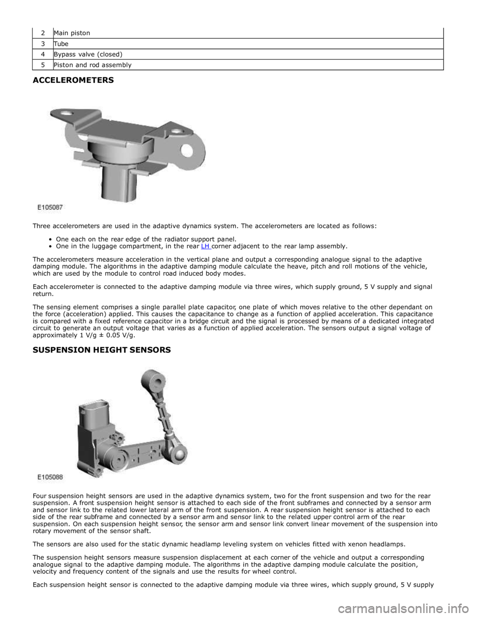
Three accelerometers are used in the adaptive dynamics system. The accelerometers are located as follows:
One each on the rear edge of the radiator support panel.
One in the luggage compartment, in the rear LH corner adjacent to the rear lamp assembly.
The accelerometers measure acceleration in the vertical plane and output a corresponding analogue signal to the adaptive
damping module. The algorithms in the adaptive damping module calculate the heave, pitch and roll motions of the vehicle,
which are used by the module to control road induced body modes.
Each accelerometer is connected to the adaptive damping module via three wires, which supply ground, 5 V supply and signal
return.
The sensing element comprises a single parallel plate capacitor, one plate of which moves relative to the other dependant on
the force (acceleration) applied. This causes the capacitance to change as a function of applied acceleration. This capacitance
is compared with a fixed reference capacitor in a bridge circuit and the signal is processed by means of a dedicated integrated
circuit to generate an output voltage that varies as a function of applied acceleration. The sensors output a signal voltage of
approximately 1 V/g ± 0.05 V/g.
SUSPENSION HEIGHT SENSORS
Four suspension height sensors are used in the adaptive dynamics system, two for the front suspension and two for the rear
suspension. A front suspension height sensor is attached to each side of the front subframes and connected by a sensor arm
and sensor link to the related lower lateral arm of the front suspension. A rear suspension height sensor is attached to each
side of the rear subframe and connected by a sensor arm and sensor link to the related upper control arm of the rear
suspension. On each suspension height sensor, the sensor arm and sensor link convert linear movement of the suspension into
rotary movement of the sensor shaft.
The sensors are also used for the static dynamic headlamp leveling system on vehicles fitted with xenon headlamps.
The suspension height sensors measure suspension displacement at each corner of the vehicle and output a corresponding
analogue signal to the adaptive damping module. The algorithms in the adaptive damping module calculate the position,
velocity and frequency content of the signals and use the results for wheel control.
Each suspension height sensor is connected to the adaptive damping module via three wires, which supply ground, 5 V supply
Page 741 of 3039
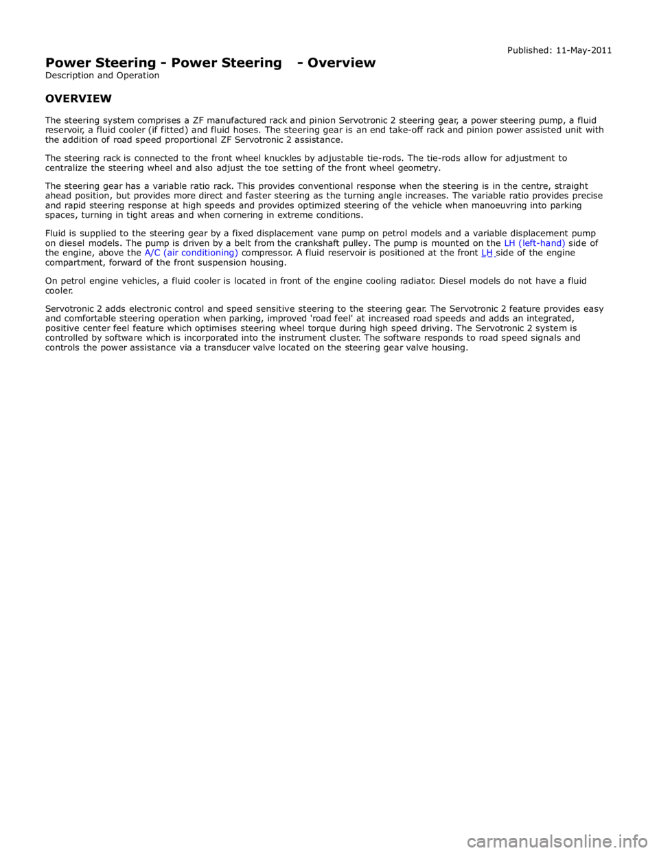
compartment, forward of the front suspension housing.
On petrol engine vehicles, a fluid cooler is located in front of the engine cooling radiator. Diesel models do not have a fluid
cooler.
Servotronic 2 adds electronic control and speed sensitive steering to the steering gear. The Servotronic 2 feature provides easy
and comfortable steering operation when parking, improved 'road feel' at increased road speeds and adds an integrated,
positive center feel feature which optimises steering wheel torque during high speed driving. The Servotronic 2 system is
controlled by software which is incorporated into the instrument cluster. The software responds to road speed signals and
controls the power assistance via a transducer valve located on the steering gear valve housing.
Page 1107 of 3039
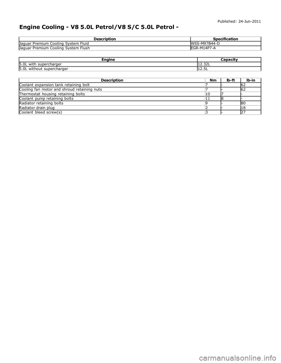
Jaguar Premium Cooling System Fluid WSS-M97B44-D Jaguar Premium Cooling System Flush EGR-M14P7-A
Engine Capacity 5.0L with supercharger 12.32L 5.0L without supercharger 12.5L
Description Nm lb-ft lb-in Coolant expansion tank retaining bolt 7 - 62 Cooling fan motor and shroud retaining nuts 7 - 62 Thermostat housing retaining bolts 10 7 - Coolant pump retaining bolts 11 8 - Radiator retaining bolts 9 - 80 Radiator drain plug 2 - 18 Coolant bleed screw(s) 3 - 27
Page 1109 of 3039

1 Engine vent hose 2 Throttle 3 Coolant expansion tank 4 Bleed point 5 Throttle body heater hose 6 Engine oil cooler 7 Engine block heater (110 V version shown) or drain plug 8 Coolant supply/expansion hose 9 Outlet tube 10 Radiator upper hose 11 Supercharger cooling system connecting hose 12 Auxiliary radiator supply hose 13 Auxiliary radiator return hose 14 Auxiliary radiator 15 Transmission fluid cooler supply and return hoses 16 Transmission fluid cooler 17 Heater core supply and return hoses 18 Heater manifold 19 Radiator lower hose 20 Cooling fan 21 Thermostat 22 Coolant pump 23 Radiator